-
Using node-red for advanced automation
06/25/2017 at 22:46 • 0 commentsHow weird, things are getting useful. This project is all about integrating powerful components of others and Node-RED is a good example of such a component:
![]()
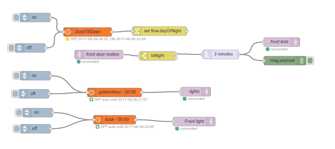
The flow above shows a Node-RED flow. "Front leds" and "Front light" are lights near the front door and "lights" are living room lights. This flow makes sure that lights in the house and near the front door are on in the evening. After dusk, if the front door motion sensor senses, well, motion, the LED lighting near the front door is switched on for 3 minutes after the last motion was seen. The other front door light does not react to motion: the bulb if of the fluorescent energy-saving type and I don't want to switch it on- and off too often.
All of this is controlled with two spider devices (one is actually a breadboarded prototype). Each of the spiders still uses an esp8266 to communicate. This is about to change. The next stop in this project is to bridge mqtt across nrf24l01+ connections. The goal: a minimum-cost minimum power wireless pir motion sensor.
-
Connecting Sensors and Switches
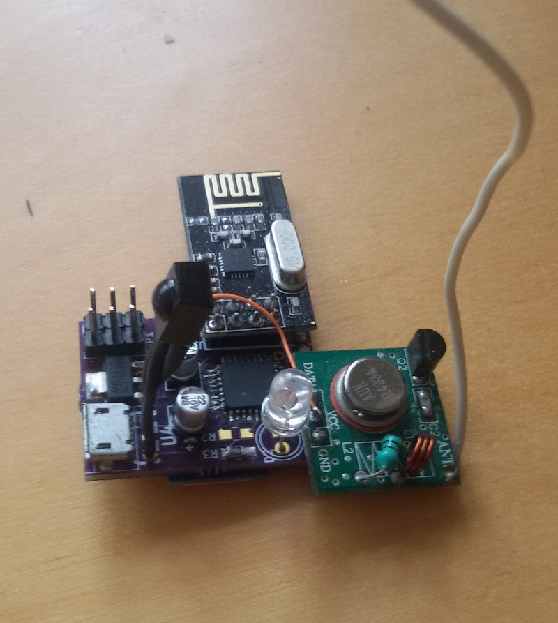
06/11/2017 at 22:04 • 0 commentsToday, two spider devices communicated with each other for the first time, and it worked! In this setup, an AVR with IR sensor detects motion at the front door and signals this to an MQTT broker. A Spider device listens to the message and switches on a light inside the house using an RF socket switch. Schematically:
![]()
The following video shows the system in action.
Of course this is not a realistic setup, but it shows the concept and there's something very satisfying in seeing the system react in a fairly sophisticated way.
The Software Setup
Being a software developer, I can't help but explain in some detail how the software for this project is now set up. To be honest, this example is somewhat hacked. To start with, the sensor board was programmed to directly publish to the MQTT topic of the light switches:
    using esp_link::mqtt::setup;
    using esp_link::mqtt::publish;
    const char topic[] = "spider/switch/0";

    while (not esp.sync()) /*repeat*/;
    esp.execute( setup, nullptr, nullptr, nullptr, nullptr);

    for (;;)
    {
        esp.execute( publish, topic, "0", 0, 0);
        wait_for_movement();
        fade( leds, true); // fade in

        esp.execute( publish, topic, "1", 0, 0);
        wait_for_non_movement();
        fade( leds, false); // fade out
    }
This code will publish a "0" to topic "spider/switch/0" and then wait for the PIR sensor to show movement. As soon as movement is detected, it will publish a "1" to that same topic and then wait until an (arbitrarily chosen) 30s period passes without movement, after which it will send a "0" again, etc.This direct connection between sensor and switch is not supposed to happen. Really, the sensor should just publish to its own topic, e.g. "spider/sensor/<n>" and the home automation software should take over from there and publish to the switch topic.
The spider software for the switch had already been programmed before. As stated previously, it subscribes to the topic "spider/switch/+" and will react to messages by sending "on" and "off" pulse trains to the 433 Mhz transmitter. The setup looks like this:
    using esp_link::mqtt::setup;
    using esp_link::mqtt::subscribe;

    // get startup logging of the uart out of the way.
    _delay_ms( 5000); // wait for an eternity.
    while (not esp.sync()) toggle( led);

    esp.execute( setup,     nullptr, nullptr, nullptr, &update);
    esp.execute( subscribe, "spider/switch/+", 0);

    for (;;)
    {
        esp.try_receive();
    }
This code registers the function update() as a callback for new messages. The update function itself checks whether the topic of the message is the one it expects and will then parse the switch number and the number in the message:void update( const esp_link::packet *p, uint16_t size) { using namespace esp_link; packet_parser parser{ p}; string_ref topic; string_ref message; parser.get( topic); parser.get( message); const char *topic_ptr = topic.buffer; const char *topic_end = topic_ptr + topic.len; // if the topic is indeed the expected one... if (consume(topic_ptr, topic_end, "spider/switch/")) { // ...try to parse the switch number from the topic and the // on/off number from the message. uint8_t sw = parse_uint16( topic_ptr, topic_end); uint8_t onoff = parse_uint16(message.buffer, message.buffer + message.len); // ... and send the corresponding code. sendcode( sw, onoff); } }More details about the implementation of sendcode() are in the source file and were described in the previous log. -
Switching lights with MQTT
06/10/2017 at 22:44 • 0 commentsMQTT is working!
Spider can now successfully subscribe to an MQTT topic and switch RF wall switches.
There are still some hard-coded constants that need to become configurable in EEPROM in the future, but in essence switching the lights works as intended.
The software consists of a firmware and a library that contains the esp-link client code to talk MQTT with the outside world.
The new firmware subscribes to the topic "spider/switch/+" and expects messages to "spider/switch/<switch number>" the message itself should be either "0" (off) or "1" (on). What happens when such a message arrives is determined by a data structure that is currently constant, but should be stored in EEPROM in a later stage.
Sending to RF switches
The <switch number> part of the topic is used to index into an array that is initialized as follows:
const Switch switches[] =
{
        { quigg,  { 0b01000001000000001101,     // off
                    0b11001001000000001101}     // on
        },
        { impuls, { 0b1011101010101110000000000,// off
                    0b1110101010101110000000000}// on
        },
        { impuls, { 0b1011101011101010000000000,// off
                    0b1110101011101010000000000}// on
        }
};
Each element of this array defines a pair of codes (one for "off" (0) and one for "on" (1)) to be sent and an index into an array that describes the protocols to be used. The MQTT message, 0 or 1 is used to select one of the two codes in the structures above. "quigg" and "impuls" are just constants that represent two brands of inexpensive (3 for €10,-) RF controlled switches:
constexpr int quigg  = 0;
constexpr int impuls = 1;
I had reverse engineered the protocols for these switches earlier and that gives me a data structure to describe the protocols for these switches:struct Encoding { /// how long to wait between sending the same signal again in units of /// 4 microseconds. uint16_t us4_between_repeats; /// how many bits in one transmission uint8_t bits; /// whether to invert the signal and if so: how long to wait after inversion /// in units of 4 microseconds uint16_t us4_delay_after_invert; /// describes a single symbol, usually a 1 or a 0 typedef uint16_t Symbol[2]; /// describes the symbols for a 0 bit and for a 1 bit Symbol alphabet[2]; };This video shows how I reverse engineer the signals for my switches using a horrible contraption that I made earlier:
...and this gives me the following numbers for my switches:
// describe the known protocols constexpr Encoding symbols[] = { // quigg { 17000, 20, 175,{ { 175, 350 }, { 350, 175 } } }, // impuls { 1500, 25, 0, { { 140, 49 }, { 42, 147 } } } }; -
esp-link MQTT software
05/28/2017 at 19:46 • 0 commentsSpider uses esp-link for its wifi connectivity. This custom esp8266 firmware offers many functions in addition to plain network connectivity. The one feature that was very useful from day one was the AVR firmware update: An avr with a suitable boot loader can receive firmware updates over WiFi via the esp.
Spider uses the optiboot boot loader. This means it's flashable through its serial port. It should even be possible to flash a Spider board from the Arduino IDE, although most programs will probably not work as expected due to the 8 Mhz clock.
Another nice feature of esp-link is that it can take care of maintaining a connection with an MQTT-broker. It allows the AVR to publish messages and to subscribe to topics. The AVR and esp-link must use the SLIP protocol in order to have both plain serial communications and in-band esp-link commands on the same serial port.
For Arduino, there is already an esp-link client library that takes care of the SLIP communications and the format of the command packets that are sent from and to the esp-link. Stubbornly, I decided that this library could not be used for Spider:
- The Arduino library depends on the Arduino environment and, for instance, the Arduino serial port. This would mean that in order to use the library, I'd have to use the Arduino environment and somehow adapt for the 8Mhz clock. All in all not impossible, but quite an undertaking. Additionally I have some fears that depending on Arduino libraries would cost me more program space and RAM than I have available (Spider uses an Atmega328 or Atmega88).
- Although the esp-link client library is well-written, it is written in C++'03. C++11 offers features that make programming for microcontrollers a lot easier and I thought it would be a good exercise for both the modern C++ muscles and the microcontroller C++ muscles to write my own version.
In other words: I'm a walking example of the NIH syndrome.
The library is still a work-in-progress. As always, writing my own version of this library took way more time than predicted. It has also taught me a lot about how the esp-link firmware works though, so in the end I don't consider it a complete waste of time.
-
Hardware revisions
05/20/2017 at 21:53 • 0 commentsThe PCB has undergone some revisions since I've started the project:
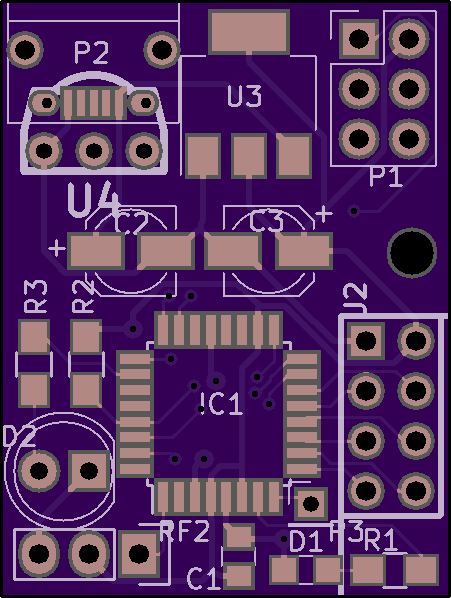
Version 1 was the first board ordered from oshpark:
![]()
This board works OK, but had a few issues:
- I had forgotten to pull down GPIO15 on the ESP. This means the module won't boot properly and this had to be fixed with a patch wire
- I used a TSOP2438 footprint for the IR receiver, but I found out I had a HS0038. This meant I had Vcc and GND reversed. This was easily fixed by bending the pins on the receiver and adding some heat shrink to prevent shorts.
- The micro-USB-B connector is supposed to stick out about 1mm from the board, but I had aligned it with the edge. This meant that the connector is pushed up a little at the edge.
- The 433 Mhz transmitter was powered from 3.3V regulator. Presumably 5V would give better signal and from previous experiments I knew I could power it at 5V and still signal it from 3.3V.
- Some weird conflict occurred between the ams1117 on my PCB and the one on the USBasp AVR programmer, which broke the 3.3V power on the USBasp. All of this happened with no power applied to the spider board.
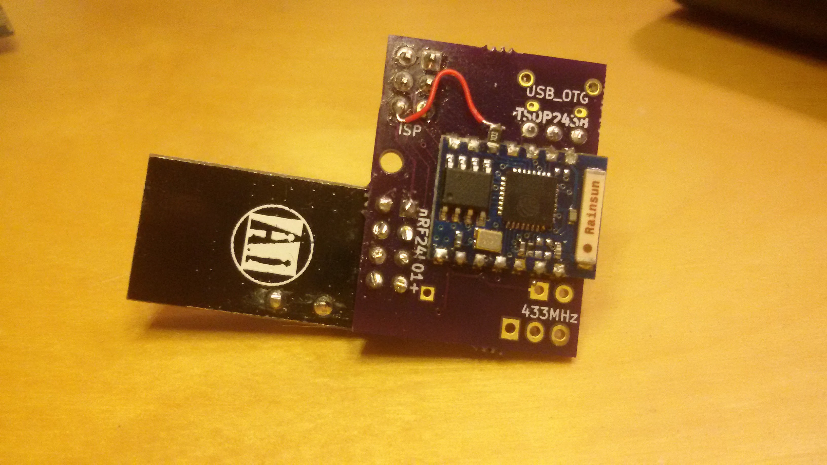
The patches are visible in these images:
![]()
![]()
Version 2 has a few improvements:
- GPIO15 pull down, 5V to 433Mhz transmitter, IR receiver and USB connector issues were fixed
- More AVR GPIOs were broken out to a header, including the uart IO lines which make it possible to also flash the ESP through the header
- The 5V is now also available there. This made it a lot easier to connect a PIR sensor. In version 1 I only had 3.3V available on the header, which meant I had to bypass the regulator that is normally present on the PIR sensor module.
- The header is now female, so that I can push some extra long pins in the header for AVR programming. This way I can leave out the Vcc pin which in turn means that the power on the board and the (new) USBasp are no longer connected.
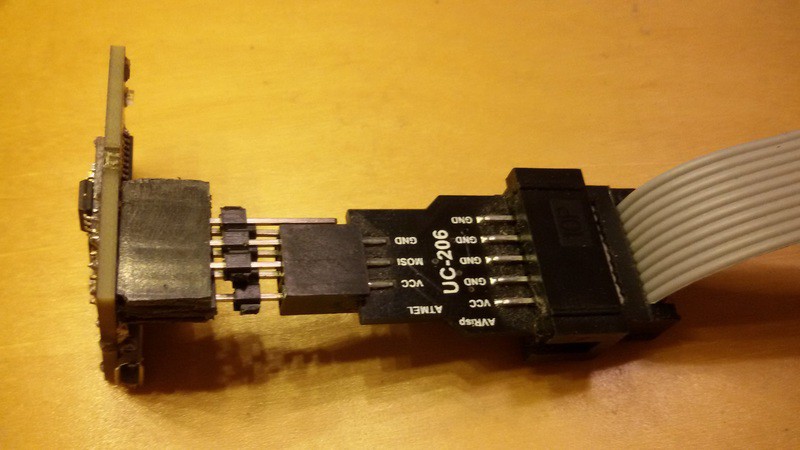
The following picture show the setup for programming the bootloader into the AVR. If you look closely, you'll see that the Vcc is disconnected. Also visible is the USB connector on the bottom that now extends from the PCB.
![]()
Small adjustments are still made to the design although I haven't ordered new boards of this revision yet. The most notable change is that I'm now including small solder mask lines between the pads of the atmega. This should make it a little bit easier to solder the pins of the TQFP package.