-
One shots and Zero Crossing Detector
09/30/2015 at 03:50 • 0 commentsI've been testing the one shot library, and the zero crossing detector, everything seems to be working perfectly!
![]()
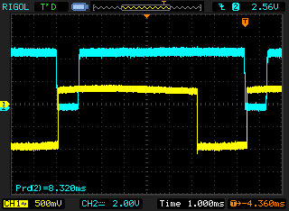
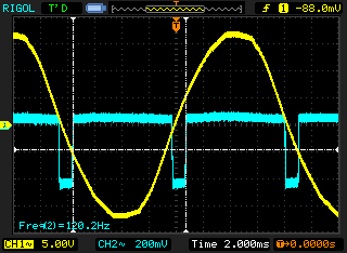
The blue trace is the output of the zero crossing detector, the yellow is the one shot output from OC0B.
The blue goes low when the AC input is near or at 0 volts. This allows for the detection of both rising and falling crossings, though the distinction does not matter for this project.
The yellow trace goes low to activate the opto-isolator and triac. Because the triac will not de-energize until a zero crossing (0V potential across its terminals), in order to have variable control we must activate the triac some variable time after the zero crossing.
Because the AVR is triggering on the falling edge of the zero crossing, we can have the opto disabled before the zero crossing rises, and not have to worry about the triac being activated early.However, because the PID will require a steady timebase, we'll need to test if the fluctuating 60hz AC is stable enough to drive the calculations... That would make all of this quite easy, just recalculate the PID value on every INT0!
![]()
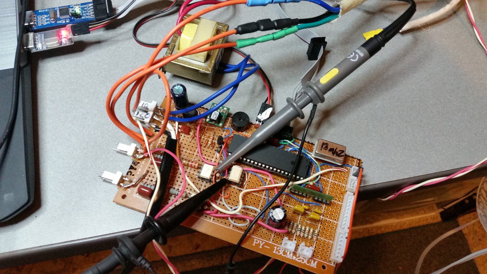
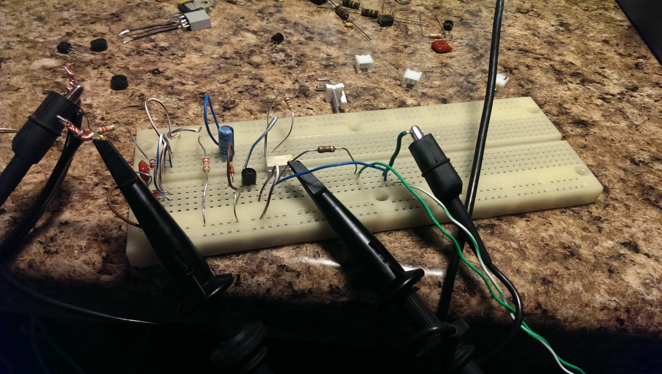
The perfboard prototype! 120VAC is hardwired into the zero crossing circuit. The transformer is a stand-in for the huge toroid in the T-870a, and provides 10vac to the power supply section. The triac in the T-870a is connected via the crimp connectors and orange wires.
With this setup, I was able to both dim an incandescent lamp, and "dim" a fan, as tests. Everything worked flawlessly, though this was a simple test of the one shots and INT0. The real test will come when integrating the PID into the mix. -
Pulling my hair out!
09/23/2015 at 03:46 • 0 commentsMy struggles with this continue, and I have no idea what the cause is.
After some googling, it seems that there are a handful of possibilities, most of which I have ruled out.
My only lead is that I was occasionally able to get the program to function properly once, while plugging and unplugging the usbASP. I wonder if it is causing some sort of reset loop, or if it is a problem with Windows.
If I am unable to resolve this, I fear I will have to change hardware, which is not something I wish to do.
My trusty STM32's I use at work have never had issues like these.....
-
Not diggin' AVR so much right now
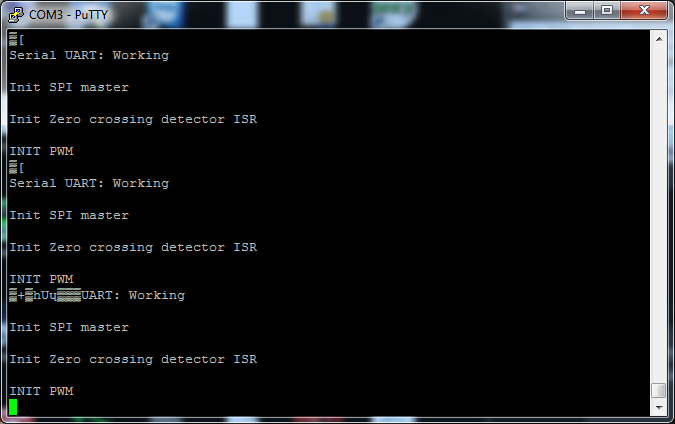
09/22/2015 at 05:08 • 0 commentsI've been trying to get all the code together, but I keep running into unusual issues with the AVR. The code is doing some unusual bootloop, which started when trying to push floats via printf. Unless I find the cause I'll have to write my own float to string function.
![]()
-
It's not dead yet!
08/17/2015 at 16:05 • 0 commentsPersonal life got in the way, plus lack of interest. Now back in full force!
Finished soldering up a perfboard copy of the hardware design, which is a good thing because I discovered a few things I needed to change, more on that in the next post.
Brief update is, hardware is solid so far, finished up code for the ADS1118, ran a calibration curve on the thermocouples (they're k-type, much to my surprise!), Finished writing a library to allow the usage of the '328's timers as one shots, thanks to an excellent write-up here. Also have external interrupts working using INT0, connected to the zero-crossing detector.
I migrated to eclipse, using the eclipse-avr plugin with gcc support, though unfortunately it doesn't support gdb directly, I'll have to look into that, but so far I haven't needed it.
There's a new BitBucket link to the repo, it was easier to make a new one rather than trying to retool the old one, since eclipse is kinda nasty when it comes to work spaces.
What still remains is integrating all of the individual code components, everything works in isolation so far.
Expect another update with pictures and more details very soon!
-
Added a few AVR libraries
08/19/2014 at 15:12 • 0 commentsI've uploaded a few old libraries I wrote to the Bitbucket.
Haven't had time to test them yet, but they seem to be alright.
Feel free to take a look/ridicule if you'd like.
-
Remaining steps
08/19/2014 at 15:01 • 0 commentsOutlined below are the remaining steps to have a functional prototype:
Software:
-AVR code for handling interrupts(from zero-crossing) and timers
-AVR code for communication with ADS1118 (I have a previous library I wrote for it)
-AVR code for PWM output to the optoisolators
-AVR code for serial communication (Libraries exist)
-AVR code for LCD interface (Libraries exist)
Hardware:
-Connect LCD
-Research off-the-shelf soldering irons
-Test ADC spi interface
-I feel like I should throw some buttons and LEDs in there somewhere for good measure :)
-
Triac circuit works! (with video!)
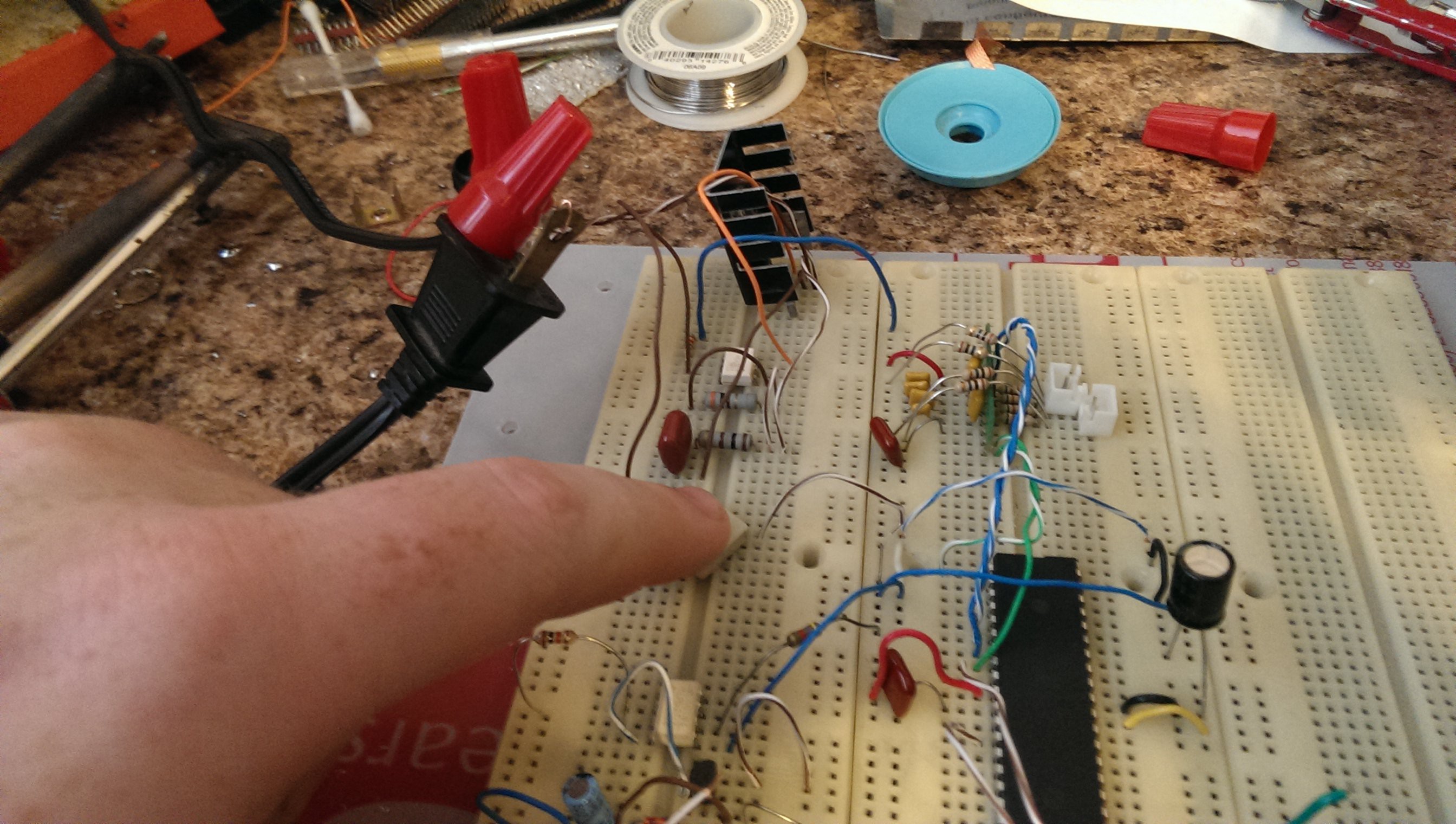
08/19/2014 at 04:29 • 0 commentsThe triac/optocoupler circuit works! It ought to, considering how simple it is, but still, it's exciting!
![]()
Youtube:
-
Schematic up on Bitbucket!
08/19/2014 at 04:19 • 0 commentsI've uploaded the initial schematic to my Bitbucket.
This includes the updated Zero-crossing detector, basic atmega324 support circuitry, and the optocoupler/triac circuit.This is very much a WIP, but please, let me know if you find any issues.
-
Zero-crossing detector
08/18/2014 at 06:36 • 0 commentsAfter some research and a good bit of tinkering/testing, I've settled on a design for the zero-crossing detector.
The design is based off of the one at http://www.dextrel.net/diyzerocrosser.htm
with some minor changes to fit what I had on hand.It produces very good results:
![]()
![]()
The purpose of the zero-crossing detector is to permit phase-based control of the AC powered lamp and heatbed. By knowing when the mains voltage is at zero, the controller can switch the AC on/off and have a variable phase drive. If, for example, power were to be switched on for a few ms, the heat from the lamp would be very different if power came on it the trough of the AC, versus the crest.
Open Rework Controller (ORC)
PCB and PC Host software for controlling an infrared rework station
