Close
0%
0%

L.A.S.E.R. Tag Control

A control board for the Graffiti Research Labs excellent L.A.S.E.R. Tag graffiti system

Similar projects worth following

For The Gathering we thought it would be cool to try out the Graffiti Research Labs excellent laser graffiti system. But that wasn't enough of a hack for us, so we decided to create a control console to make it easier to change colors, brush styles and width.

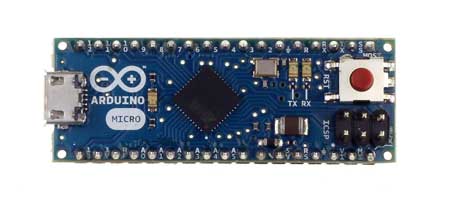
The control console will consist of an Arduino Micro emulating a USB keyboard sending sequences of keypress events to the GRLs Laser Tag software to navigate the menus and change settings. It will include some big buttons, switches and encoders to make controlling the system easy.

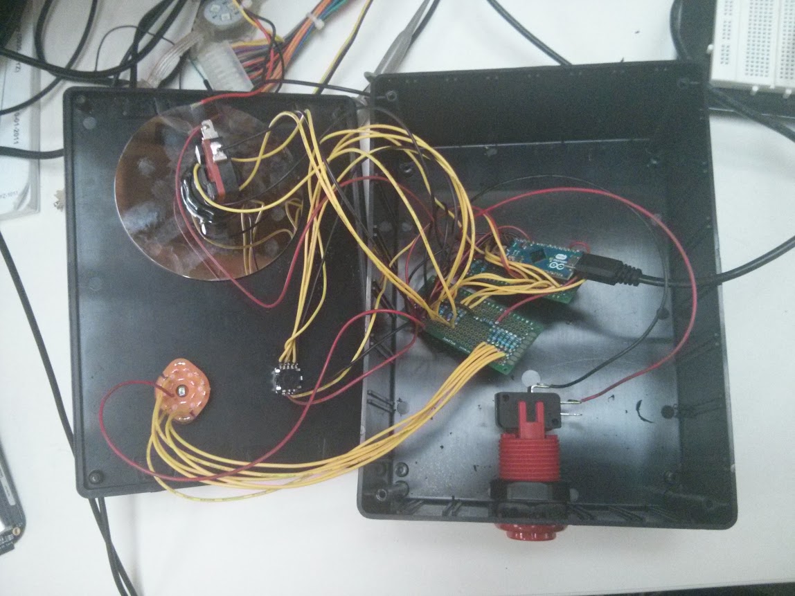
Hardware setup expects an Arduino Micro with the following hardware attached:

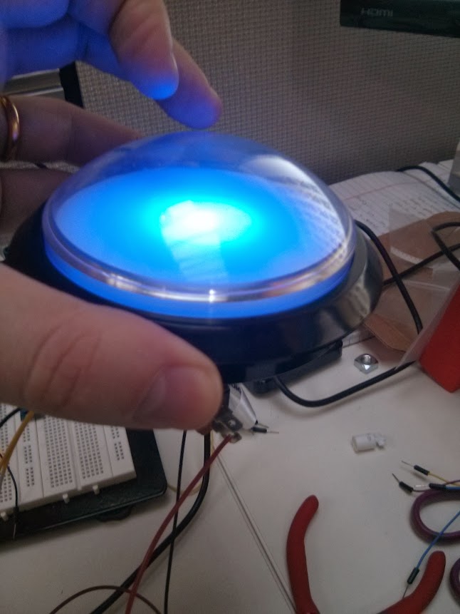
​Big Dome Button hacked to support RGB LED, microswitch normally open pin connected to pin 12, Common Anode RGB pins connected to PWM pins 9, 10 and 11.

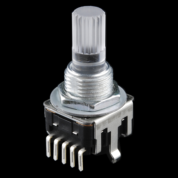
​RGB Illuminated Rotary Encoder with RGB pins connected to PWM pins 5, 6 and 13, and the 2 encoder pins connected to pins 2 and 3.

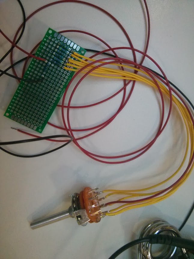
​6 position rotary switch connected through a 6 level voltage divider connected to analog pin A0.

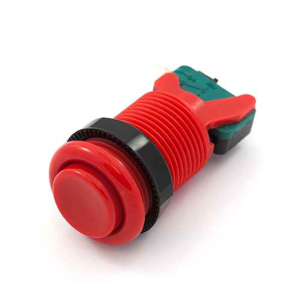
​Arcade push button connected to pin 8.

  • 1 × Wide angle common anode RGB LED
  • 1 × RGB rotary encoder
  • 1 × Arduino Micro
  • 1 × White big dome button
  • 5 × 68ohm resistors

View all 10 components

  • Enclosures

    Ben Delarre01/16/2014 at 01:22 0 comments

    Now we couldn't very well let 500 hackers mess around with a bunch of open wires, so we needed to make a little enclosure for our control system. The simplest way to do this was to grab an off the shelf project enclosure from Radioshack.

    We had to drill a bunch of holes to fit our various components, this proved to be a bigger challenge than we had first anticipated since we inevitably didn't have the right size drill bits. After a bit of procrastination we bit the bullet and drilled 4 holes for the big dome switch, the rotary encoder, rotary switch and the clear button. However... it turns out we didn't expect the plastic to melt while drilling in the way it did, leaving us with holes bigger than they were expected to be.

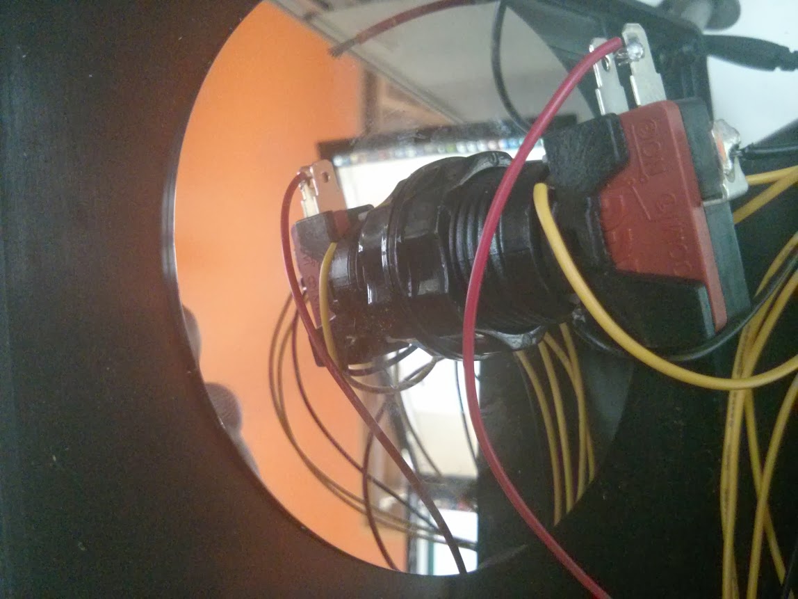
    For the big dome, we found that the clamp nut fell straight through the hole, making it impossible to secure the dome switch properly. So we dived into our parts box looking for something we could use as a washer. Thankfully we found this perfectly sized hard drive disk platter which did the job nicely:

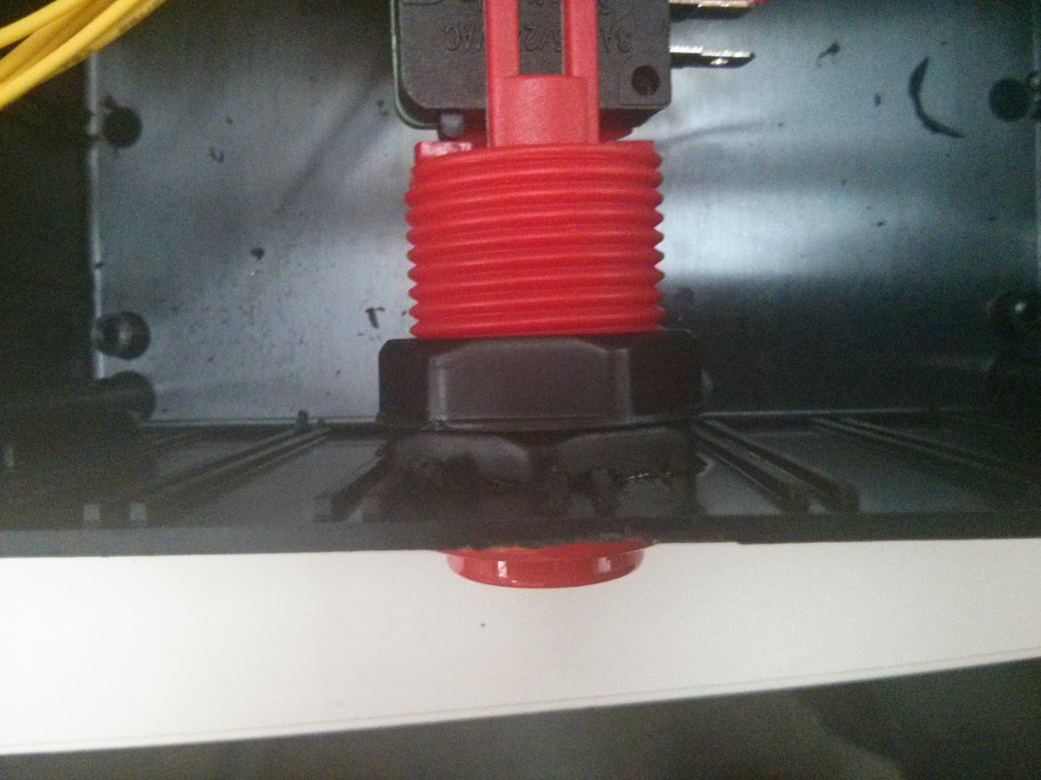
    Next we found that the arcade button fell through the hole at certain angles. This was really annoying as it was almost exactly the right size, but not quite. Thankfully though we'd bought two of these switches so we wound the clamping nut tightly onto the shaft and pushed it through the hole which after a bit of action with the dremel was now a perfect fit. We then used the nut from the second button to clamp it all into place. It seems good and solid now:

    Then it was just a case of putting all the additional wiring in place and fixing the Arduino and protoboards into place and securing the rotary encoder and switch.

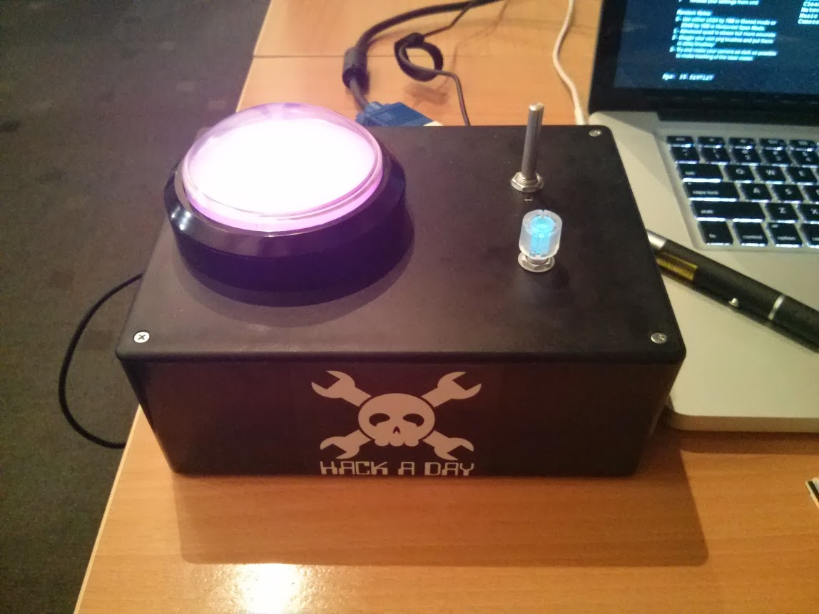
    Thankfully this was the last major problem we had and now the case looks great. We still need to buy a knob for that rotary switch, but I think this will do...the HackADay sticker really finishes it off don't you think?


  • A little Arduino goes a long way...

    Ben Delarre01/16/2014 at 01:10 0 comments

    Yes yes, I know, Arduinos are lame. But... they are incredibly handy for getting certain things done really quickly.

    For the control system we need to emulate a USB keyboard, it just so happens the Arduino Micro is especially good at this. With a simple line of code you can easily send arbitrary keypresses to your computer without any effort at all. So we're going to use one for our system.

    We're going to hook a few basic components to our Arduino, we've already covered the Big Dome button. Besides changing color we want to be able to modify brush width. This is a value from 2 to 128, so we decided a rotary encoder would be best, so we grabbed one of these Illuminated Rotary Encoders from SparkFun. These let us not only read a continuous stream of values, but they also have an embedded RGB LED that we can use to provide some feedback.

    These encoders are actually a little complex to read, they only require two pins but you need to read their values very carefully to determine which way the encoder has been rotated. Here's a quick snippet of code showing how to use them:

    /* Rotary encoder read example */
    #define ENC_A 2
    #define ENC_B 3
    #define ENC_PORT PIND
    #define MASK 0x03
    void setup()
    {
    /* Setup encoder pins as inputs */
    pinMode(ENC_A, INPUT);
    digitalWrite(ENC_A, HIGH);
    pinMode(ENC_B, INPUT);
    digitalWrite(ENC_B, HIGH);
    Serial.begin (115200);
    Serial.println("Start");
    }
    void loop(){
    int tmpdata = brushSize();
    Serial.println(tmpdata, DEC);
    }
    int brushSize()
    {
    static uint8_t counter = 2; //this variable will be changed by encoder input
    int8_t tmpdata;
    tmpdata = read_encoder();
    if( tmpdata ) {
    counter += tmpdata;
    if (counter < 2)
    counter=2;
    if (counter > 254 )
    counter = 254;
    }
    return counter/2+1;
    }
    /* returns change in encoder state (-1,0,1) */
    int8_t read_encoder()
    {
    static int8_t enc_states[] = {
    0,-1,1,0,1,0,0,-1,-1,0,0,1,0,1,-1,0 };
    static uint8_t old_AB = 0;
    /**/
    old_AB <<= 2; //remember previous state
    old_AB |= ( ENC_PORT & MASK ); //add current state
    return ( enc_states[( old_AB & 0x0f )]);
    }

    We also want to be able to modify brush shape, for this we have 6 values, so we grabbed a basic rotary switch from RadioShack. This switch would really require us to use 6 pins, one for each position, unfortunately we don't really have that many pins and it would vastly complicate our reading of the values anyway, so we came up with a quick hack using a simple voltage divider circuit and one of the analog pins to read a different voltage at each pin position.

    Here's the code for reading the value based on a selection of resistor values, dead simple right?

    int getBrush() {
    int val = analogRead(BRUSH_SWITCH_PIN);

    if (val > 950)
    return 0;
    else if (val > 700)
    return 1;
    else if(val > 450)
    return 2;
    else if(val > 250)
    return 3;
    else if(val > 75)
    return 4;
    else
    return 5;
    }

    Finally we added one of these simple arcade style buttons so we can clear the display.


  • An RGB button...

    Ben Delarre01/16/2014 at 00:55 0 comments

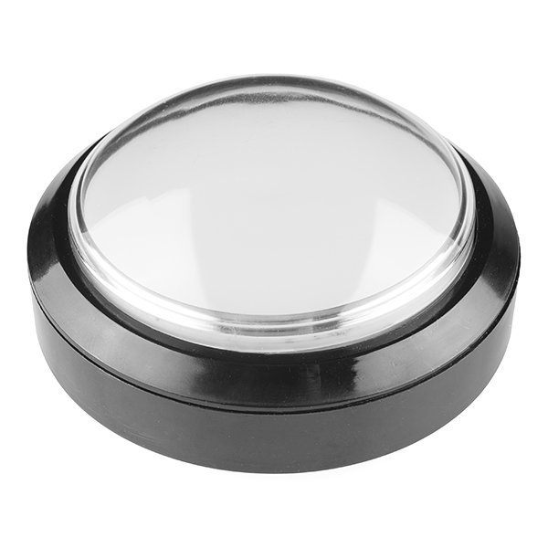
    I really like these big dome buttons from SparkFun, but they don't come in an RGB flavour. This is really annoying as they would be ideal for the color control on our system.

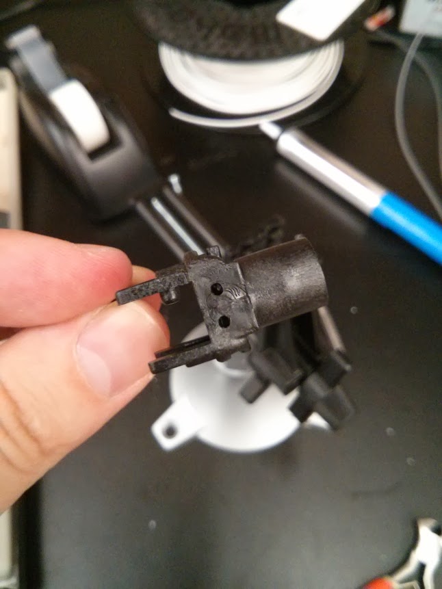
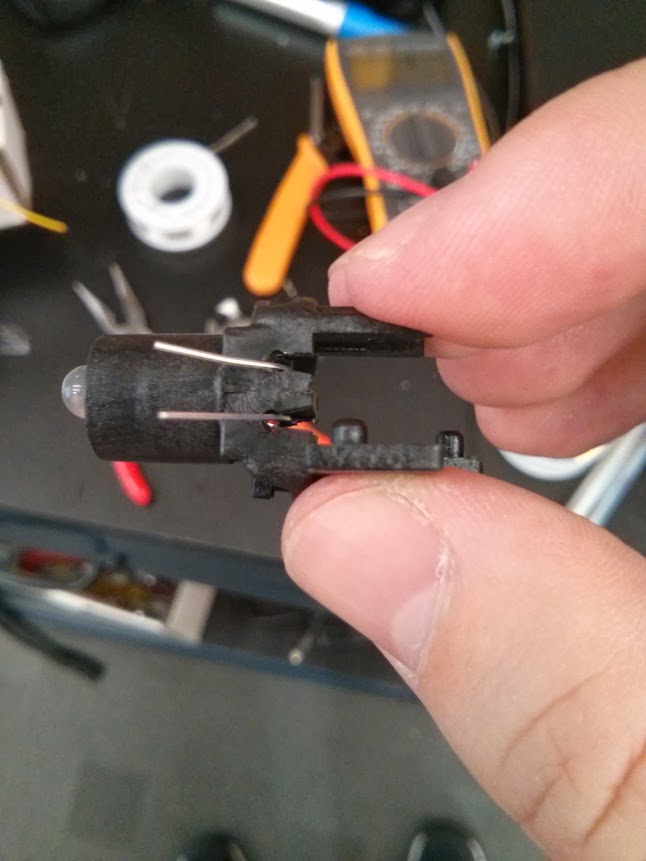
    Not to worry though, a couple of minutes with some snips and a soldering iron and this can be easily solved. First disassemble the button and extract out the LED holder and the metal clips that connect to the LED pins. These are easily pulled out with some pliers. After you've pulled the metal clips out drill 4 small holes in the plastic for your LED channels.

    Now snip out channels to these holes with a pair of snips. You should now be able to put your wide angle RGB led into place and bend the pins to hold it all secure. 

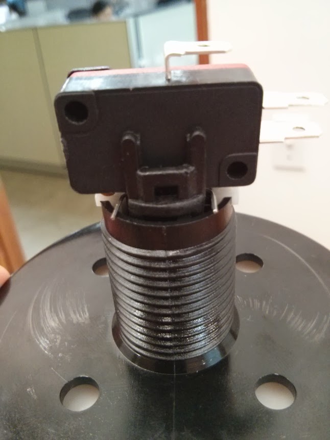
    If you did it right you should be able to put the microswitch back into place without it impacting the pins.

    Now you solder 4 wires to the RGB LED pins and you are good to go!


  • GRL!

    Ben Delarre01/16/2014 at 00:45 0 comments

    In 2002 the Graffiti Research Lab put together the rather excellent L.A.S.E.R. Tag system which allows you to draw virtual graffiti with nothing more than a camera, a projector and a laser pointer. They've done really awesome things with this showing it off around the world, virtually defacing buildings everywhere.

    In the planning stages of the HackADay Gathering meetup we decided we needed something for all the hackers to play with and someone floated the idea of setting up the laser tag system in the space. This didn't seem like enough of a hack to me so I decided we should build a control system for it to make it easier to use.

    Unfortunately we couldn't get a working copy of the Laser Tag source so we have had to improvise. Most options in the system are available through a cursor navigated menu system, so we thought we could quickly use an Arduino to simulate a USB keyboard and send the appropriate keypresses. So we're going to put together a control box with a couple of buttons and switches to control the main features of the software, Brush Color, Brush Size and Brush Shape.

View all 4 project logs

Enjoy this project?

Share

Discussions

niftylight wrote 03/31/2014 at 07:49 point
If you want even more hacking, you should check out the "unofficial linux port" https://code.google.com/p/lasertraq/ that uses gStreamer + webcam + laserpointer for emulating a mouse to control any kind of application.

  Are you sure? yes | no

pjkim00 wrote 01/24/2014 at 17:53 point
My kids really enjoyed the Lasertag setup at the LA gathering. I was looking into setting up a system at home but can't seem to find the source code. I found a URL:
http://openframeworks.cc/lasertag/LaserTag2002Xcode.zip

which you would think would like to a zip file but instead it goes to a page with video links, forum comments, etc. Any ideas on where I can grab the source code?

  Are you sure? yes | no

Ben Delarre wrote 01/25/2014 at 02:22 point
Hey,

So the only copy of the source I found was on Github: https://github.com/LeonFedotov/L.A.S.E.R.-TAG-GRL

But The Internet Archive appear to have taken a shot of the URL you linked to above: http://web.archive.org/web/20111216074518/http://www.openframeworks.cc/lasertag/LaserTag2002Xcode.zip so that might be a better one.

  Are you sure? yes | no

Similar Projects

Does this project spark your interest?

Become a member to follow this project and never miss any updates