 markcra
-
1Step 1
Electrical assembly
- Desolder the connectors on the ULM2008 boards (too tall for fitting into body).
- Solder wires in their place, crimp dupont male ends (or simply tin the ends with a soldering iron and tidy so they will fit securely into a breadboard).
- Front/robot-right motor driver goes to pins 4-7, Rear/robot-left motor driver goes to pins 8-11.
- Wire the positive tab of a battery pack to the negative tab on the second battery pack.
- Wire (red) the positive tab of the second battery pack to a switch and then wire the switch to a dupont male end to be put into Vin on the Arduino.
- Wire (black) the negative tab of the first battery pack to a dupont male end to be put into GND on the Arduino.
-
2Step 2
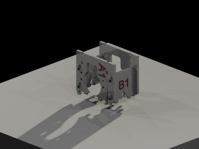
Mechanical assembly
- Stepper motors into parts A1 & A2
- Ends B1 & B2 slot into A1 & A2 to make a rectangle (B2 has no tabs, it goes in at the hook ends of A1 & A2)
![]()
-
3Step 3
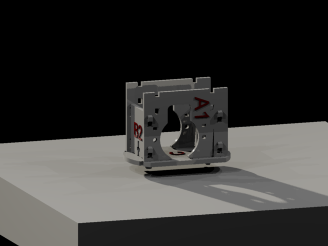
- A1,A2,B1,B2 assembly snaps into base C (line it up and pull the two spring clips back if necessary)
- Tape a nut into slots on B1 & B2 (tape on one side should be enough to stop the nut falling out)
![]()
-
4Step 4
- On D push four M3 nylon screws 25mm long through from back (side with graphic), add spacers (acrylic donuts) on three and nylon nut on top right (when looking from front) then place Arduino on top.
- To the three screws apply a stack of five spacers and to the other screw add another nylon nut, screwed down to match the level of the five spacers, put F (the breadboard caddy) on top of this and apply four nuts and finger tighten.
- On D push four M3 cheesehead nylon screws 12mm long through from front. Place battery box on top. Push two M3 nylon screws 12mm long through battery box and through D, thread on M3 nuts and finger tighten.
- Turn D over and snip protruding threads off these two screws. Place a spacer on each of the four protruding screws followed by the stepper motor driver board (preferred oriention - LEDs towards clips). Thread on M3 nuts and finger tighten, apply pressure to battery box to pinch the head of the screws if they turn freely.
- On E repeat two steps above to install battery box and motor driver board.
- On F stick solderless breadboard (suggested position is etched into acrylic).
-
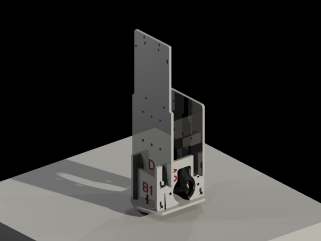
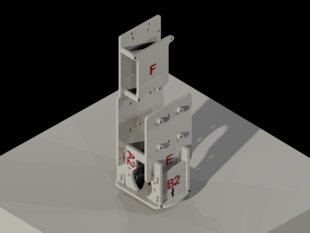
5Step 5
- To install D and E snap them into the slots above the motors with the battery boxes facing in. D, the taller of the two, goes at the back, furthest from the motor axles.
![]()
-
6Step 6
![]()
- Add one wheel (G1/G2) to each stepper motor shaft.
-
7Step 7
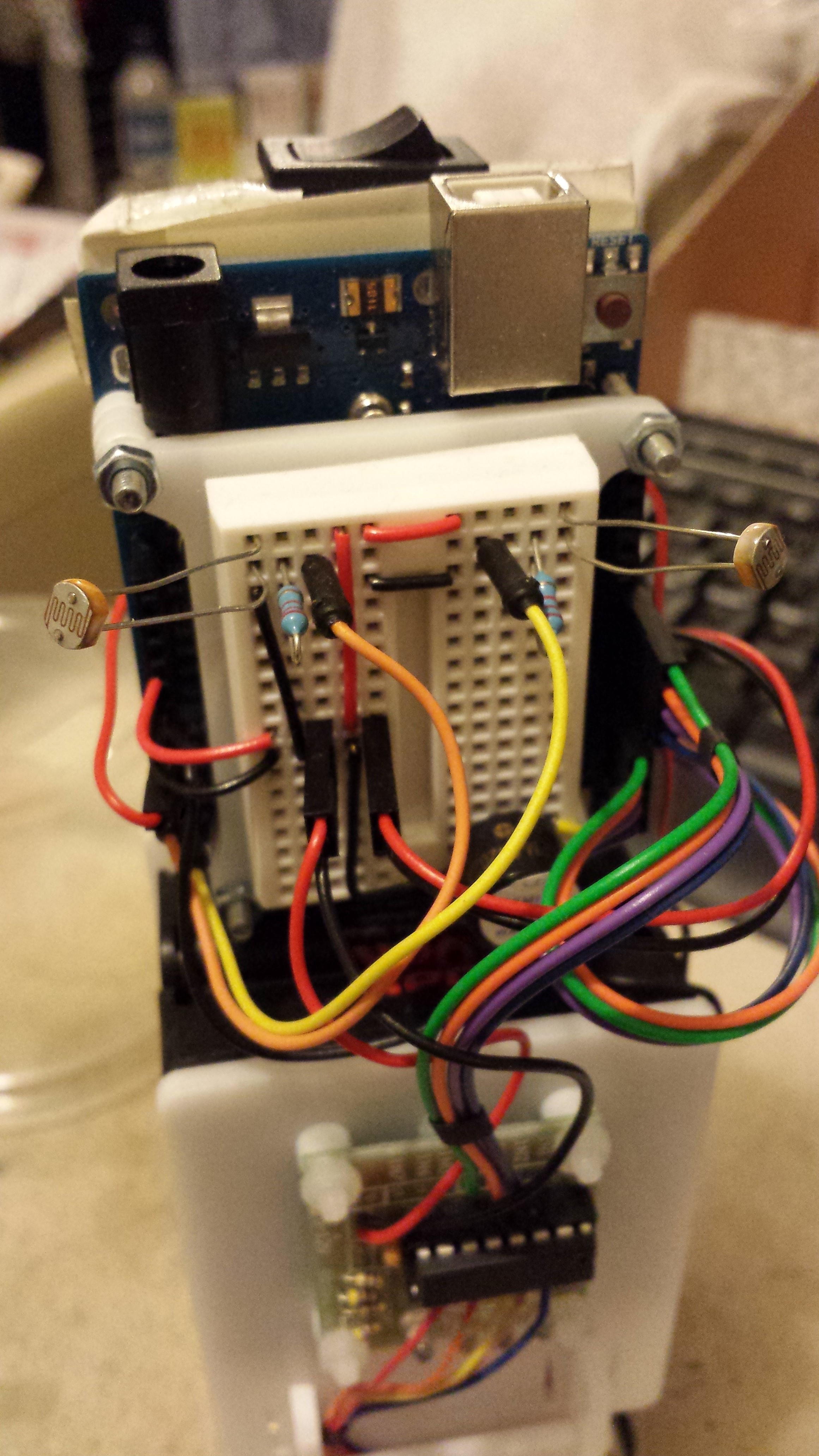
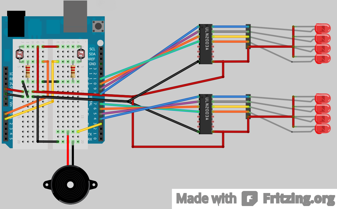
Breadboard circuit
- The light follower circuit for the workshop is made up of two LDRs in voltage dividers with 22kOhm resistors (VCC - LDR - {signal to A0} - Resistor - Ground), (VCC - LDR - {signal to A1} - Resistor - Ground).
- Additionally we supply 5v & ground to the stepper motor driver boards.
- Finally, take a wire from ground to the piezo and connected Arduino pin 3 to the piezo. A resistor might be a good idea but I ommited one.
- An LED and current limiting resistor could be wired to Arduino pin 13 for status/feedback from the sketch.
![]()
![]()
Clone of stEve
A simple laser cut acrylic robot designed for a workshop entitled "Arduino with Motors".
Discussions
Become a Hackaday.io Member
Create an account to leave a comment. Already have an account? Log In.