-
It's ALIIIIIIVE
08/19/2014 at 22:09 • 0 commentsWell, Sort of at least.
The first thing of course was to check the microcontroller and load an arduino bootloader into the system. The Atmega168 us one of the really tiny ones with only 16kb memory. The bootloader uses about 2kb so even though I started making the pogobed for fun it might save the project beacuse I can download the code without the bootloader. I hope I don't have to go down that road!
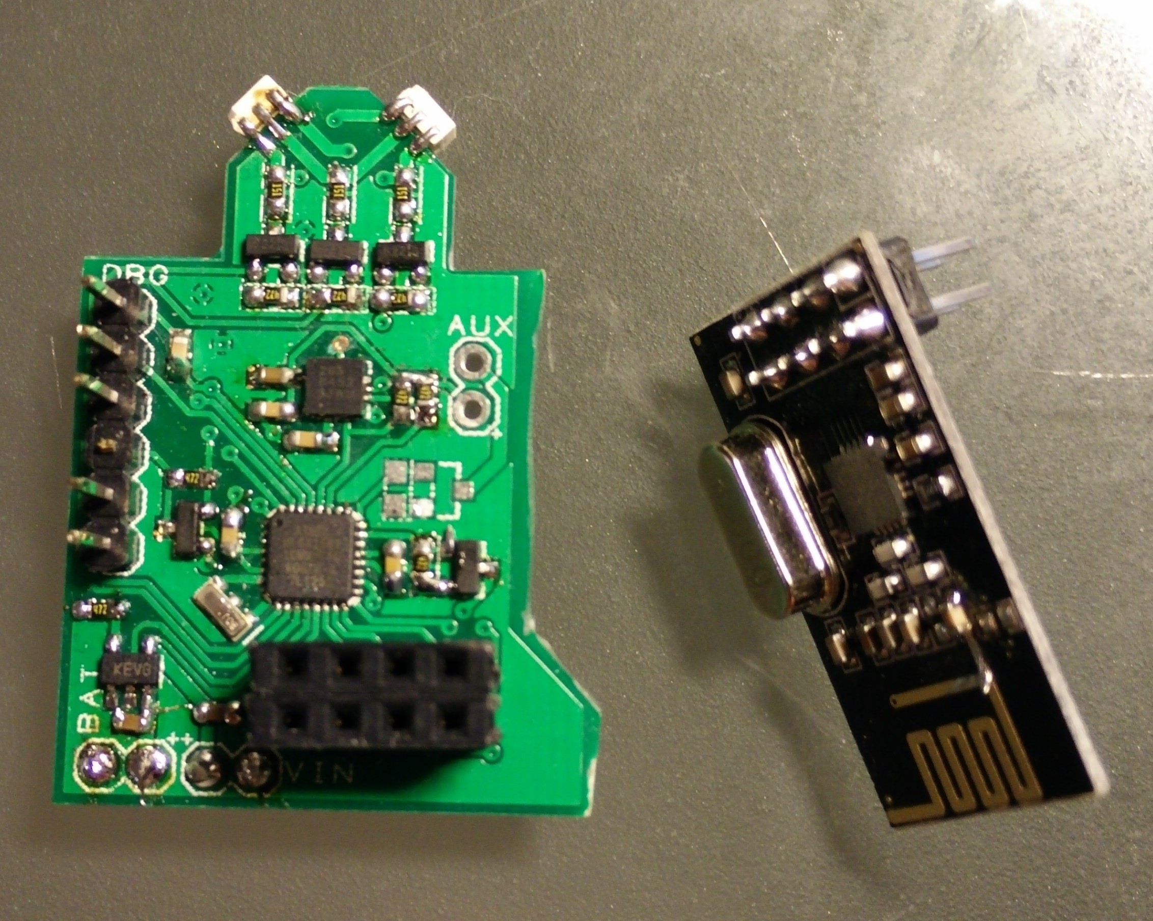
The main board with all parts (well, almost all parts) populated looks like this:
![]()
The unpopulated pads are for another NMOS transistor to drive either a buzzer or a vibration motor. another way to provide feedback to the player apart from the LEDs.
The battery charger output is connected both to the battery and to the power rail. There is a reset circuit holding the MCU in reset if (and while) the battery voltage is too low. This way all operations are halted until the battery is charged or at least starts charging again. a charging indicator light will then be powered on (blinking red every 3rd second.
After initial contact was made I soldered the RGB LEDs to the board, along with the MOSFET transistors to drive them. The reason for the drive method is that I can bump up the voltage on the diodes this way. The rest of the system runs on 3.3V. DANG! 3.3V!??! That's not the voltage my battery charger outputs!!
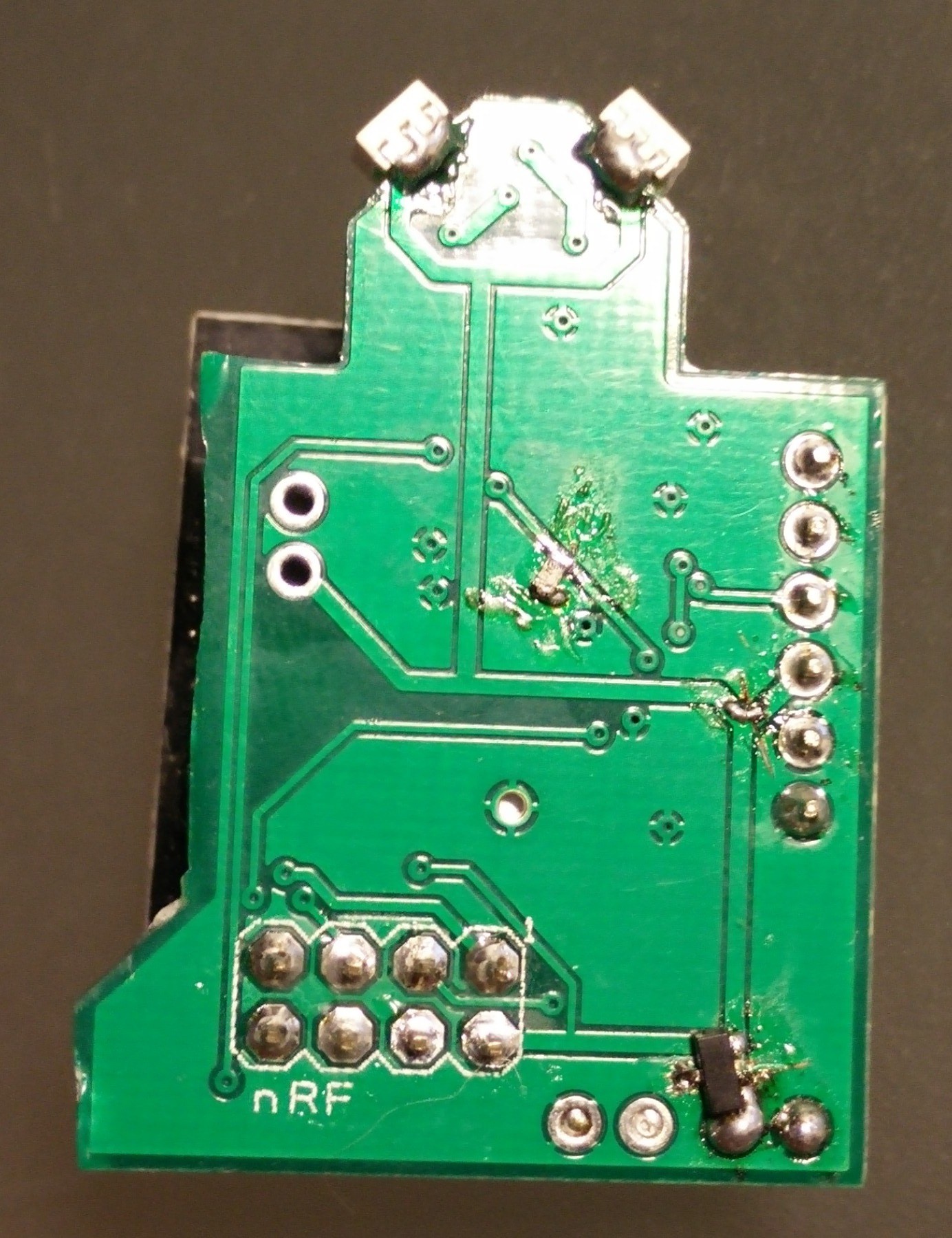
I need a 3.3V LDO and I need it to go somewhere! I might find some space on the back of the board. Let's have a look
![]()
I know - Not my brightest moment of soldering but for a prototype it'll have to do. A small SOT-23 package will deliver the 3.3V to the system and peripherals. Whew! Almost blew out those accelerometers! be careful next time!.
What I need now is I2C connection to the accelerometer. The reason this spceial accelerometer was chosen was its ability to power down while sampling. It has a built-in interrupt generator that will make an interrupt on 'transients'. a transient is exactly what I will be looking for when playing a game. A transient is a quick change in something - here it will be an acceleration. A triggered transient interrupt will mean that the player have been moving too fast! I caught you now! Time to report to the mothership and kill you ;) well, that's kinda the plan for now. We could also just reduce health or do some other stuff.. Maybe the player is immune and has a wilcard to kill another player? who knows?
-
Pogoramming
08/18/2014 at 19:47 • 0 commentsEver since I first saw the tutorial on making 'pogobeds' at SparkFun, I've wanted to build one. (https://www.sparkfun.com/tutorials/138 for those who wish to read up on it)
The biggest problem have always been that I wasn't building multiples of anything - and if I were, the projects was not my own. It wasn't until recently I started making PCBs and producing them at seedStudio. Well, I guess there's a first for everything so the OpenJoust might as well become the first of my projects to have its own programming stand with pogopins.
Apparantly pogopins are quite different. You can get them chisseled, star-shaped and coneshaped. I'd like to think that a lot of other end-options are available but I will leave them. First I got some really pointy ones, which quickly turned out to be the wrong ones. I want some pins with a head on top of them - cone shaped. Oh, and I want them to be big enough to fit the holes in the PCB.
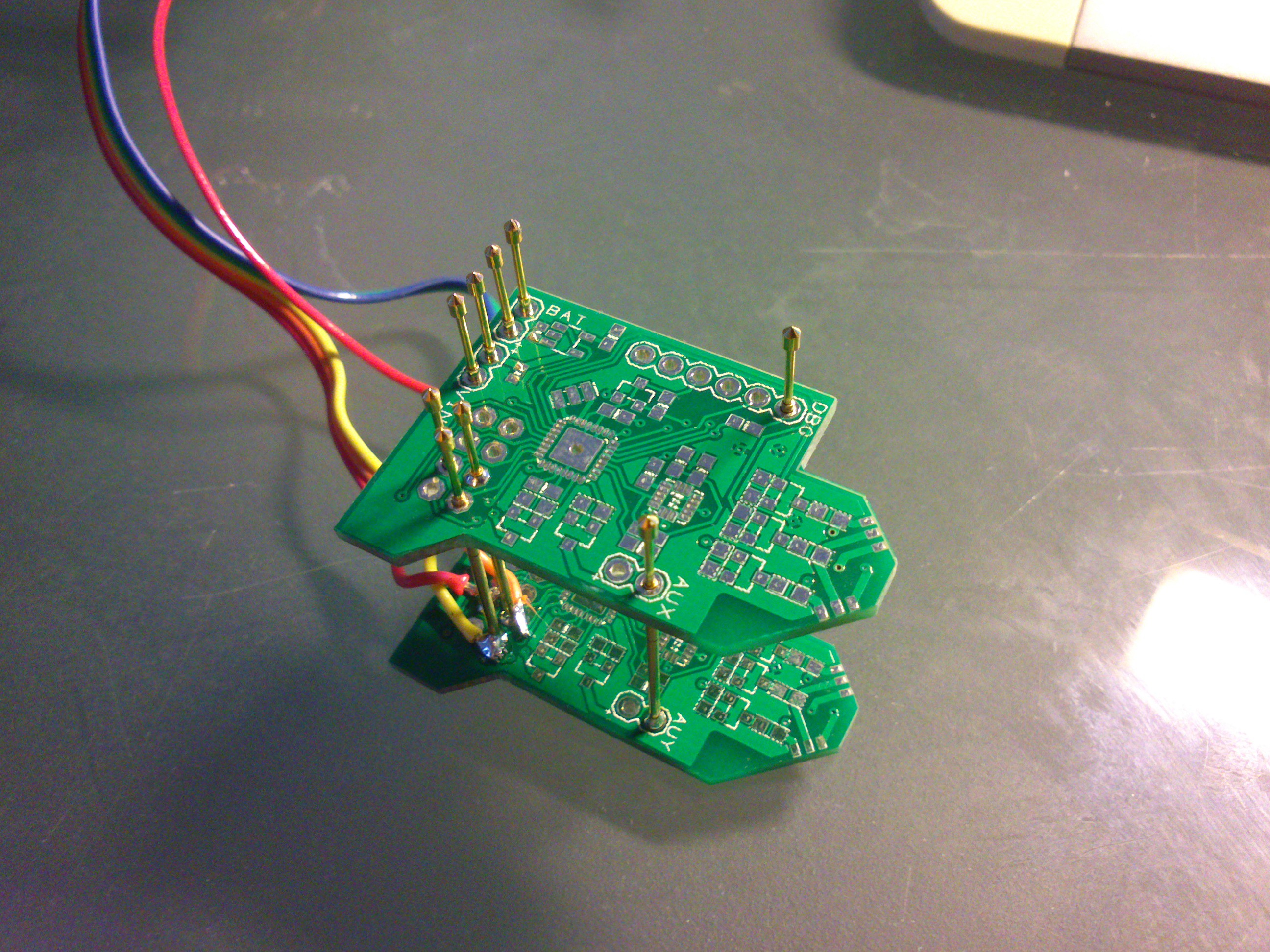
What you then do is to take two blank PCBs (well I needed blank ones because I only needed the programming and power headers to come through. Add a few extra pins for stability and Bob's your uncle.
![]()
You can easily see the small cone-shapes on top of the pogo pins. The idea is now to solder the top PCB in the right place (horisontally on all pins). The tricky part is to get both PCBs to align and be straight. if they're not then the bed will also be out of shape and the pins might not align with the device you're programming.
This is where I learned an important lesson:
ALWAYS INCLUDE ALL ICSP PINS!!!!
I thought I could get to the reset pin of the ICSP through the 'FTDI' interface. only problem is that the reset pin is connected through a 100nF series capacitor! when the programmer tries to reset the device the capacitor slows down everything and nothing works. ARGH!
Right now I can live with the task of shorting the pads for the capacitor while programming the bootloader but for buture revisions of the board I'll remember to place either a full header or at least all pins at some location on the board! Phew, I though for a moment that nothing worked. You got me all worried!
-
Getting a grip (and a charge)
08/09/2014 at 19:31 • 0 commentsIn the first project log I briefly described the controller handle. The multitude of options deserve som notion. After all the design og the handle can affect the playability and feel of the game (literally!).
First things first - how bit should the controller be? If you ever have had a playstation Move controller in your hands, you'læ know the size and weight of it. It has the dimensions for a reasen and at some point a mechanical engineer designed that controller and the looks of it. It's quite certain that the final design was also approved by the senior developers and the administration of Sony - after all that's the contrller of the console.
How should this be done then? I don't have a team of people designing this so I have to get my hands dirty. First thing to do is grab a ruler. How big is my hand? okay - 10cm across, when i close my fingers around the ruler. If the controller is less than this it'll feel like it's desappearing between my fingers. not cool. on the other hand I don't want players to be able to hit each other with the controllers so not too long either.
I aldready found a PVC pipe I could use for the handles but when it comes down to the controller design this might not be the best idea ever. Well, then again - It's quite cheap and easy to work with. My biggest issue right now it the feel of the controller. It's just a pipe. I'd like it to have a bit of ergonomics in it. Well, This might be the next revision. For now it will have to do. I just want to write it down here so the idea of having an ergonomic grip for the controller isn't completely lost.
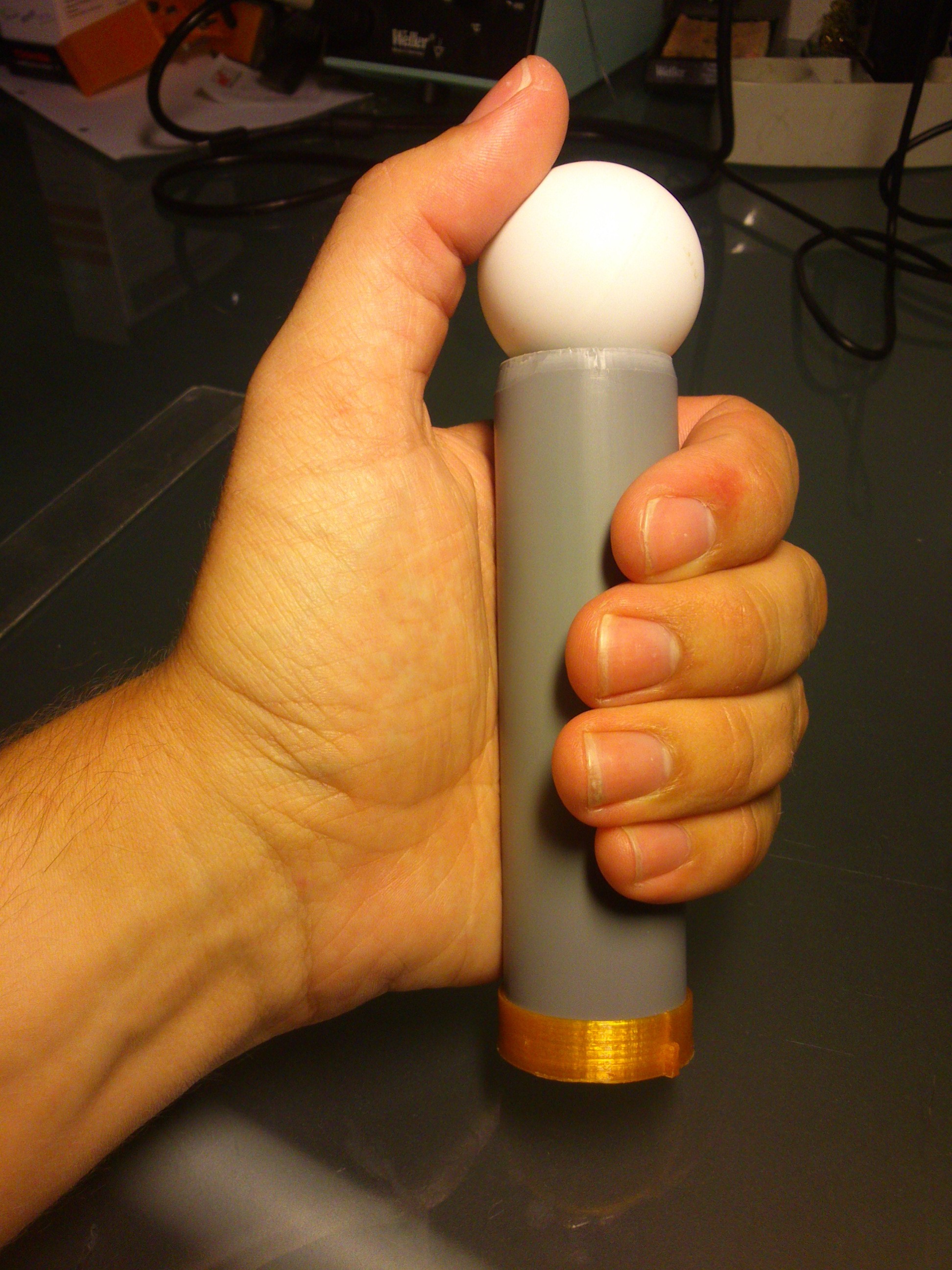
Back to the length. I decided to just try out a length - 12 cm. Just long enough so the controller wouldn't feel way too small. Remember I also have to put the pingpong ball on top. This will give a nice 'grab underneath here' feeling. The pipe has an internal diamter of 28mm - the small notch on the PCB is there to give it the final with (and some PCB to cut away if I need to make it a smalle diameter).
![]()
The pingpong ball on top finished the controller nicely. But what about the bottom? It could be open (not nice) or closed (nice). But hey - I need to be able to get to the electronics. ooh.. What about charging? Instead of needing to open the controller each time to connect a charger I might as well integrate some sort of charger system. Let's look at the options
- A connector
- removable bottom, connector behind
- induction
I like the inductive based chargers like the ones on electrical toothbrushes but I have no clue on how to design one. In the given timeframe I would probably only make that instead of the controllers.
I know for a fact that something removable introduces wear and tear. this is directly translated into a reduced life of the controller simply due to a mechanical failure.
The easiest option is some sort of connector at the bottom of the controller. A nice way to do connections is the option used on cordless phones. When put in th charging stand a small spring connector is forming the necessary connection for charging. I must be able to do something similar! Fire up the 3D printer!
![]()
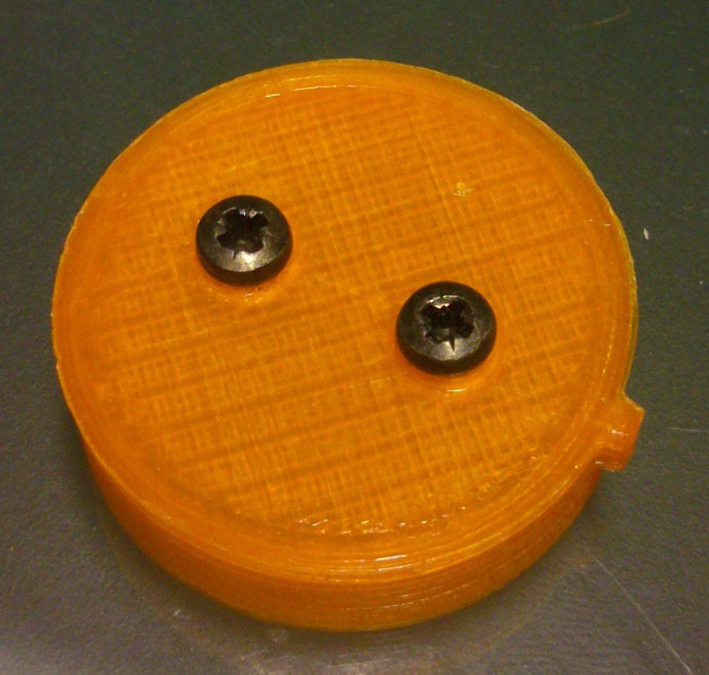
After a couple of designs I came up with this - two screws in the bottom will form the connector. Another notch will polarize the bottom of the controller.
The finished controller now look like this.
![]()
It fits nicely in the hand (I have fairly big hands). the pingpong ball is clearly visible to the players and the bottom with charger connector is fitted. Time for testing out those PCBs I got!
-
PCB Design (Rev. 1)
08/07/2014 at 14:59 • 0 commentsOf course that's an overstatement that we start directly with the PCB design - but then again it's a great way to think about the project a few times. Have I remembered everything I need? Will the controller be able to handle all peripherals? will it fit and so on.
I usually use DesignSpark PCB which is a nice free CAD tool. I prefer it over EAGLE because the library management is more intuitive (to me). I've been using it since 2009 for my home projects so this was of course the first thing to fire up for designing the OpenJoust.
The OpenJoust is based on the Arduino Pro Mini design which suits the platform nicely. The ATmega168 is (should) be more than capable of running the player node and handle communication with the main node.
One of the first things to lock during the design is the pCB outline. Is there any special requirements for the outline - mounting holes or plugs that needs to be placed in a special way? For the OpenJoust there is not special thing. only the mounting of the system is to be considered. The player should be able to hold the node in his/her hand while being able to see the indicator light.
Just like the Opentilt I found a PVC pipe for the handle - the indicater will also light up a pingpong ball on the top of the pipe. Unlike the Opentilt and more like the Move controller, the pingpong ball will not fit inside the pipe but rather 'lay' on top of the pipe.
With the handle more or less thought out I now know the with of the PCB. The internal diameter of the pipe gives this. Any component that has a significant height (radio module and headers) should be located accordingly.
PCB contents
The processor, accelerometer, radio(header), indicator lights, charger and programming pins. okay - GO!
I quickly found the different pieces. It's already worth mentioning that the accelerometer was chosen because of its ability to generate interrupts. It should be possible to configure it for transient interrupts! perfect for the Joust game: just config the whole system for a player and then go to stand-by. the player is a live until the transient interrupt is triggered and BAM! update the player status to 'dead'. nice and simple. Of course we need to check in with the main unit to see if we're the only player left but we should be able to save quite some battery during the game here!
The indicator light quickly became two RGB LEDs. I want as much light as possible which means another thing - driving the diodes directly from the battery = transistors. I have chosen a normal MOSFET N-channel for this purpose. To further help the light spread evenly in the pingpong ball I have found a small package for the LED. This allows me to mount the LED on the edge of the board rather than on top and bottom. the light should spread nice inside that ball.
Okay, enough talking, let's order the PCB's and wait!
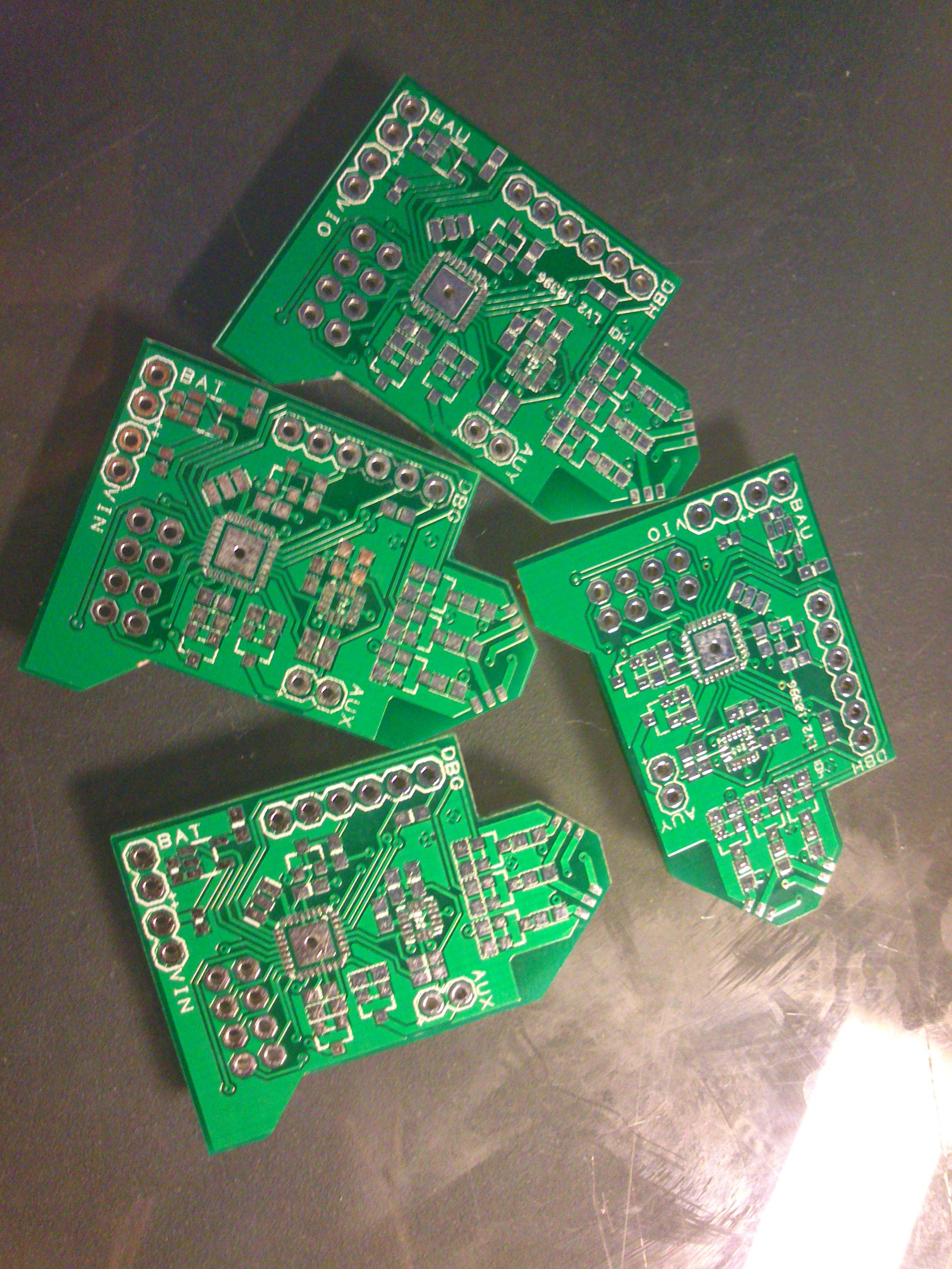
This is the result:
![]()
OpenJoust
A small and cheap controller platform for playing physical interaction games (Such as the Johann Sebastian Joust)
 HP (@banjohat)