-
Captive portal goes live
05/16/2019 at 13:11 • 0 commentsIt was a while since I put the previous project entry. Nevertheless it is better late than never, isn't it?
TL;DR
In order to operate the device using the previous version of the firmware, one needed to connect to the access point IuT_voltemeter (no password required) with their smartphone/tablet/laptop, and entering the IP address of the web server, namely 192.168.4.1, in a web browser. The new revision allows enetering any valid web address , e.g. a.uk. (Please be warned that typing any word will probably not do the trick as the browser will try to ask non-accesible search engine for entries).
The starting point for the captive portal was the CaptiveIntraWeb project developed by Andy Reischle 4 years ago. Since then the NodeMCU Lua firmware evolved to the point that this older code did not work at all, and required fixing.
Fortunately the required amends were not too difficult to debug. The amended firmware makes use of newer net.udpsocket Lua module. There is a sure possibility to take advantage of the net.dns Lua module but I decided to amend a working code rather than try to develop a new one from scratch not to getting too deep into the DNS protocol (I lightly used the following two sources that worked very well for my needs: DNS Query Message Format and DNS Response Message Format).
It was necessary to amend the Lua code that was placed into the file dns-liar.lua, and call this code from the IuT_00.lua as follows (I put this call at the very end of the file)
dofile("dns-liar1.lua")In turn, the dns-liar1.lua contained the following code where I left all the acknowledgements
-- dns-liar1.lua
--Thanks to Thomas Shaddack for optimizations - 20150707 ARe
dns_ip=wifi.ap.getip()
local i1,i2,i3,i4=dns_ip:match("(%d+)%.(%d+)%.(%d+)%.(%d+)")
x00=string.char(0)
x01=string.char(1)
-- constants required for a proper DNS reply
dns_str1=string.char(128)..x00..x00..x01..x00..x01..x00..x00..x00..x00
dns_str2=x00..x01..x00..x01..string.char(192)..string.char(12)..x00..x01..x00..x01..x00..x00..string.char(3)..x00..x00..string.char(4)
dns_strIP=string.char(i1)..string.char(i2)..string.char(i3)..string.char(i4)
--% code in this section was modified to amend the deprecated APIs
--% see for details https://nodemcu.readthedocs.io/en/master/modules/net/#netudpsocket-module
udpSocket=net.createUDPSocket()
udpSocket:on("receive", function(s, data, port, ip)
    --print(string.format("received '%s' from %s:%d", data, ip, port)) -- DEBUG
    --s:send(port, ip, "echo: " .. data) -- from the docs example replaced below
    decodedns(data)
    s:send(port, ip, dns_tr..dns_str1..dns_q..dns_str2..dns_strIP)
    collectgarbage("collect")
end)
-------------------------------------
--old callback code - deprecated
--svr:on("receive",function(svr,dns_pl)
--  print(dns_pl)
--  print(dns_tr..dns_str1..dns_q..dns_str2..dns_strIP)
--  svr:send(dns_tr..dns_str1..dns_q..dns_str2..dns_strIP)
--  collectgarbage("collect")
--end)
-------------------------------------
udpSocket:listen(53) -- DNS requests are sent to the gateway IP : 53
--%
function decodedns(dns_pl)
  local a=string.len(dns_pl)
  dns_tr = string.sub(dns_pl, 1, 2) -- get the first 2B of the request -> request ID
  local bte=""
  dns_q=""
  local i=13
  local bte2=""
  while bte2 ~= "0" do
    bte = string.byte(dns_pl,i)
    bte2 = string.format("%x", bte )
    dns_q = dns_q .. string.char(bte)
    i=i+1
  end
  --print(string.format("DNS request: '%s' for %s",dns_tr,dns_q)) -- DEBUG
end
print("DNS Server is now listening. Free Heap:", node.heap())
.
Bonus youtube link: ESP32 NodeMCU Lua Firmware - Config, build and flash | How to from Alija Bobija
-
Function, procedure, interrupt sevice routine, callback function - which is better to use?
07/16/2017 at 11:28 • 0 commentsSome time ago I came accross the term REST (ReST) and how important it was. I tried reading a lot of articles (starting from Wikipedia and ending with the likes of "How did I explain REST [and some other little things] to my wife") to get the idea. Some of the sources cited a long list of references which included PhD theses, books and internet archives going a few years back. Unfortunately I am not a diamond to be around forever and work through these lists. (Most importantly, there is no known diamond of my weight as of yet.) Therefore, when I figured out that, if I folow the table below, I comply with REST/ReST/RESTful/you_name_it
Action on resource HTTP SQL (for comparison) Create new POST CREATE Access existing GET SELECT Update existing PUT UPDATE Delete existing DELETE DROP I have got my rest despite some people would rightly say that I missed a lot of important points. This log entry is used to clarify a few points that I think are important before describing recent amendments to the firmware.
Here are my highly opinionated bullet points
1. What computers are and what they can do (preamble 1)
They are collections of CMOS gates which outputs can be in one out of two states (High/Low, 1/0, ON/OFF). A single output represents a bit. Single bits can be used for embedded developments and serial comunications (bit bang) but computers at present operate at least 8 bits or one byte at once. (The byte was adopted since IBM/360s. At present AFAIK only PIC16s allow native single bit manipulations whereas some SIMD instructions can process up to 1024 bits at once.) Stored program computers read some bytes called an instruction from an electronic memory first, then access some storage (may be from the same memory) to get the operand(s), then place these operands and operation code to the inputs of an electronic circuit called ALU to produce the result. Finally, the result goes to the designated storage. The good thing is that a computer could process millions/billions or even more instructions per second, and particular ALU designs allow interpretations of the results as additions, subtractions and so on for a trained eye.
2. What computer programming is about (preamble 2)
This is the way to define operands and instructions, and interpret the results in some human understandable way. All programming systems like C++, Arduino, OpenGL, Bootstrap etc are here to bridge the semantic gap. Most people refer to the program as to what was written by a human and to the code as to what is actually controling the computer at the run time.
3. How did the computer programming evolve (preamble 3)
First computers AFAIK operated just the fixed sequence of instruction, which was OK to compile the artillery tables they were designed for. It was no point to run such a program the second time as the results would be perfectly the same. Later computers became more useful as they included provisions to branch the code depending on some operands, and repeat the same code snippets to achieve some desired condition. IIRC a typical code consits of 60% instructions to move data around, 30% instructions to perform some actual computing, and 10% instructions to branch the code (Patterson & Hennesy ?).
However, until the development of IBM/360, computers were not code compatible, and every computer was to be manufactured to an order and was programmed individually. A big boost to the programmers' productivity came when system software called assembler was introduced to computing. Assemblers allowed writing computer codes in human readable format at the first time (e.g. write ADD R1, 25 instead of some 1010011101). With the IBM/360 it became sensible to develop high level languages that would be more easier to use by humans to program various computers in the same way by using the same piece of software called compiler.
Since then the assembly language usage was shrinking to system programming, resolving bottlenecks, access to specific computer internals, high speed and real time tasks as it can be crafted to be more efficient than what a compiler should generate for compatibility and code correctness reasons. (Notes: there is a way to include some assembly statements into high level code for the above reasons called inline assembly. Quite recent webassembly (webasm) aims to bring back native code execution to high level web programming in order to speed up code execution.)
4. How did the programming methodologies (definition of data and instructions) evolve; functions vs procedures
Integer data pieces differ by their length and whether they should be treated as having or not having the sign (e.g. uint8_t, int32_t etc). Floating point data pieces can be of two lengths, either float or double. There are also strings for text and more complicated data types starting from arrays, structures, unions and going all the way to JSON data, SQL tables, video streams etc.
90% of machine instructions are executed in sequence as only the remaining 10% branch the code. Many microcontrollers (MCUs) do not support all the arithmetic operations (rarely integer multiply, even more rarely integer division, and only recently high end MCUs started to support floating point). These operations need to be performed programmatically, taking many instructions to completion. It makes serious memory saving not to include the required code snippets every time when, say, multiplication is required, but place this code somewhere in the memory once and CALL it as needed. Explicit CALL instruction is required in assembly, and it is followed by the memory address of the code snippet. In high level languages it is enough to write the name of the required code module followed by the list of the parameters (e.g. multiplicands). If the code returns a value, it is called a function, otherwise it is called a procedure or a subroutine. Code modules facilitate programs reuse and sharing, and in high level languages isolate parts of code from each other preventing various bugs. They are also very useful to hide the actual program complexity. For example, a single high level statement like
printf ( "%f", sin(angle*pi/180) );would require execution of perhaps a few hundreds of machine instructions. Competent use of subroutines/functions was called procedural programming. (Note: inline keyword for the higher speed of execution.)Code branching is implemented using if..them..else; switch; try...catch. Loops are defined using for; do...while; while... . Using these constructs only with appropriate indentation was used to be called structural programming. At present in some languages (Python) one simply cannot program any other way.
Object-oriented programming, among some other things, allows encapsulating relevant data (called members) and procedures (called methods) into programming constructs of then novel type called objects.
5. Interrupts and interrupt service routines (ISRs)
Most computers need to keep some attention to the events that are asynchronous to the code execution (e.g. they need to react when the user taps the touch screen or a particular time interval, set by an internal timer, has expired). There is the need to process such an interrupt to the main code's execution then come back and resume the interrupted code. A piece of code (program) that handles this actions is called the interrupt service routine (ISR), and for a good reason as effectively it handles some call but the call made by internal or external hardware.
The ISR needs to save the state of the interrupted code, do what is required then restore operation of the interrupted code. These actions are straightforward in high level languages (interrupt keyword) but can be quite peculiar in assembly (already mentioned PIC16).
On the other hand, a programmer can prepare and list parameters for any procedure/function before calling them. In contrast an interrupt can happen any time, and it is neither possible to supply some actual parameters to the ISR nor use the ISR result(s) directly. Global (or extern) variables need to be used for this purpose instead.
An ISR should operate some hardware relevant to the triggered interrupt, in particular clear the interrupt flag (this action can be facilitated by some code generating tools like STM32CubeMX).
Therefore an ISR can be treated as a procedure that responds to asynchronous internal and external events (interrupts), and exchange data through some globally defined variables.
6. Callback functions
I experienced callbacks at first when started using MATLAB GUIs. These functions were called by the MATLAB interpreter when the user performed some GUI-related action like entering text or simply clicking the mouse. Using these callbacks relieves the programmers from programming a lot of things like processing the mouse interrupt, figure out what application it was relevant to, call the application's relevant subroutine etc. Eventually I was able to, instead of editing script files, enter the required simulation parameters in a GUI window then click the "start" button to run the code, which was very handy.
Callback operation is especially important for ESP8266/85 as WiFi communications need to be processed and acknowledged in some timely and conventional manner. Letting the users to write their own ISRs could easily break both the correct data exchange and RF compliance requirements. Therefore the built in ESP firmware handles the RF interrupts then calls the programmer's supplied code (callback function) to process the communication outcomes according to the intended application.
Callback support is included in some programming languages like Lua and Javascript. As the callback function is called by some intermediary, the relevant parameters can be passed onto it, and the result used directly. (Note : both Lua and Javascript allow anonymous (nameless) callback functions.)
Therefore a callback function can be treated as a procedure that responds to some asynchronous external or internal events and is called not by the event itself but by some middleware instead, which can supply the parameters and utilise the returned value.
-
Made for each other: B0505 and Wemos mini
07/07/2017 at 14:00 • 0 commentsThe original intention was to equip the IuT voltemter with a LiPo battery and a battery shield with the view to have an isolated instrument like any digital multimeter (DMM). I found that using the shield with a quite beefy 720 mAh battery lasted for the 4 hours I specified for the design. Unfortunately this combination wasted more power than I could tolerate, and pushed the cost of the instrument up too high to my liking. I decided to look for an alternative solution.
First I would like to discuss why did I want to have an isolated instrument. I am sure for most breadboard prototyping needs it is perfectly fine to have the voltemeter powered from a power bank or even a mains adaptor. However some measurements (e.g. high side current measurements) do require isolation of the device-under-test (DUT) and IuT voltmeter's grounds. There are some inexpensive isolation DC/DC convereters available, and this log entry describes how the voltmeter performed when it was powered from the B0505 1W converter.
A B0505 part serves just this and no other purpose - to isolate ground potential of the power supply from the ground potential of the load. As electric current can only flow through some circular (closed) path, accidentally connecting two circuit nodes from the isolated power domains results in no current flow. Therefore an isolated voltmeter will happily measure differential voltage on a high side shunt resistor whereas non-isolated one will be in most cases driven to saturation at best. I used B0505 1W because I got some on a cheap from Aliexpress before; more suitable B0503, which outputs 3.3V, and could power the 3.3V raildirectly (without wasting 33% of the consumed power on the linear volatge regulator), seemed to be less common thus more expensive and difficult to get.
I wanted to figure out whether the converters I have got
- could supply enough power to drive the two modules
- whether the supplied curent is clean enough not to cause erroneous readings of the ADC
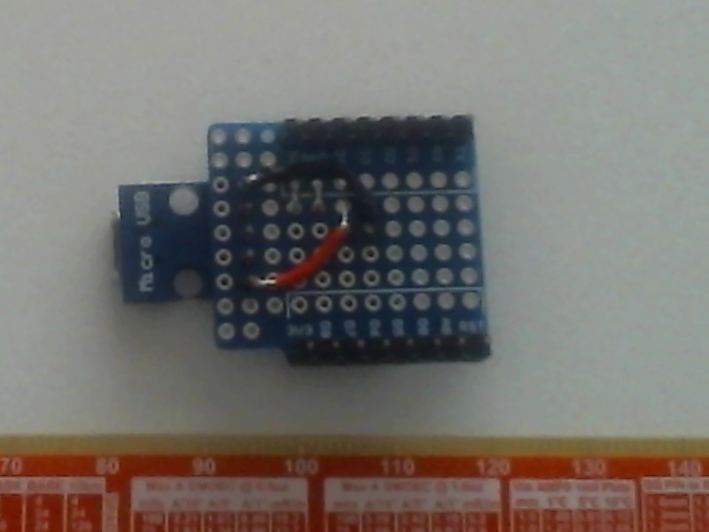
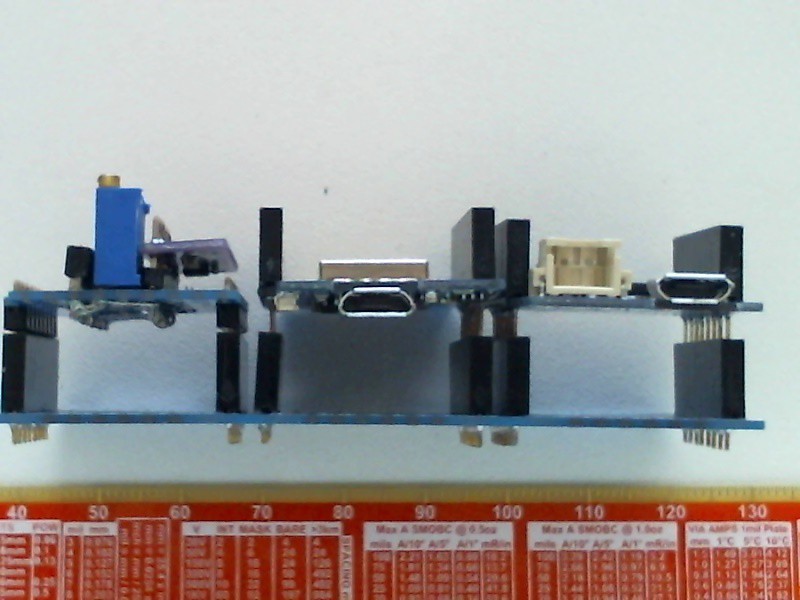
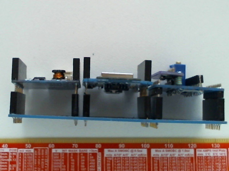
I have used a protoype shield, micro USB breakout board and B0505 converter connected as shown below
![]()
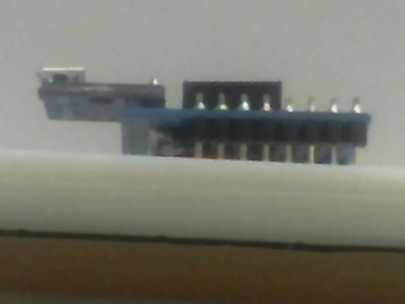
Top view above does not do justice to the awesome look of the assembeled custom shield; the picture below gives much better impression of the artifact despite the best focus I could get was not good enough.
![]()
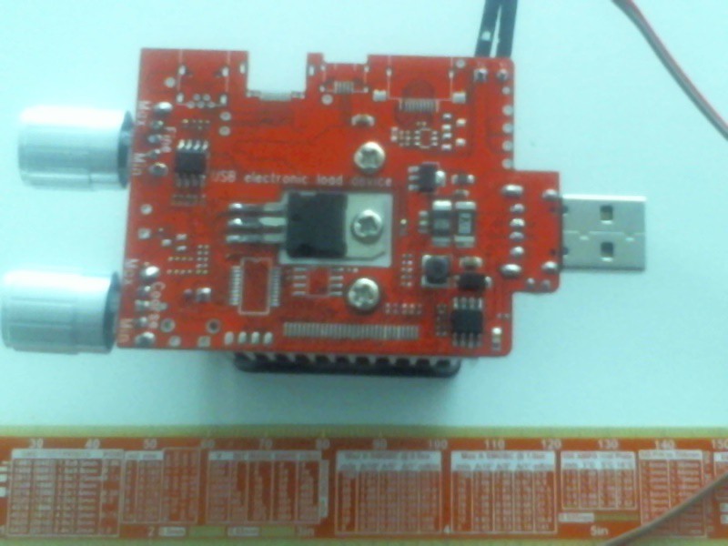
I tested power conversion capabilities of the B0505 in a proper manner using an electronic load (pictured below)
![]()
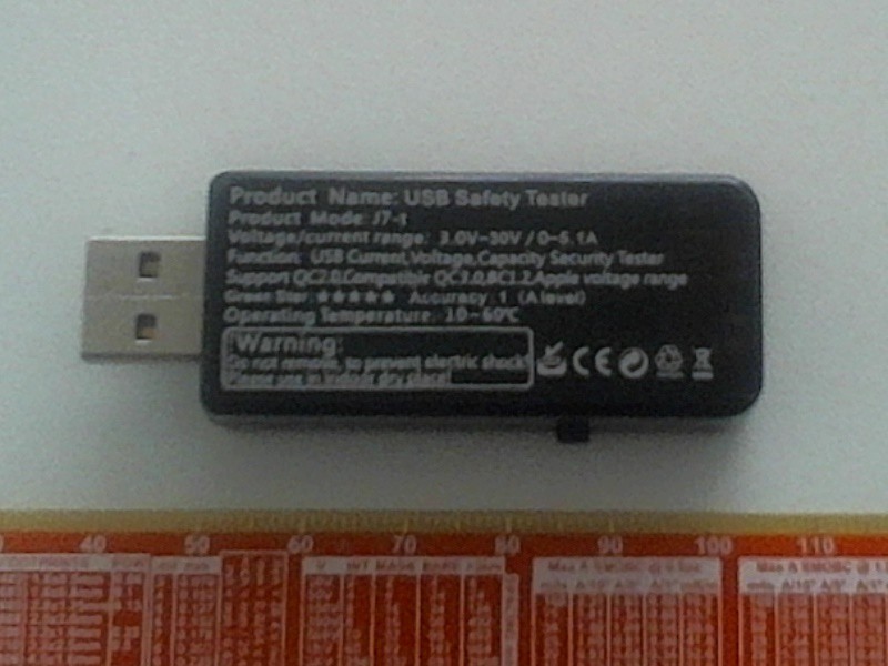
and a very handy tool (a.k.a. USB safety tester) that I use for power measurements within its operating range (3-30V, 0-5A):
![]()
The USB safety tester was plugged into a wall adapter rated at 5 V, 3 A; its output was connected to the custom B0505 mini shield. The electronic load and a DMM were connected to the B0505's isolated power output in parallel. By regulating the load I set various currents flowing into the B0505; these currents usually fluctuated by 10-20 mA thus the recorded data can be slightly off.
Vin,V Iin, mA Vout, V Comment 5.09 0 5.65 no load at all;
not permitted by the manufacturer5.10 50 5.36 5.09 100 5.19 5.06 150 5.04 5.01 200 4.82 4.96 250 4.68 worked for a long time without hard overheating; slightly above its specified output power maximum rating (4.68*0.25 = 1.17 > 1 (W) ) 4.94 300 4.53 just checked because the power was notably higher than the specified rating (I have had two more modules thus could gamble; 4.53*0.3 = 1.36 >> 1 (W) ) Wemos mini features a linear low drop out (LDO) regulator RT8013 that can tolerate the no-load output volatge of a B0505; current consumption of an ESP peaks at 170 mA at most. Therefore B0505 seems to be suitable for powering the IuT volmeter. Moreover, because of the presence of this regulator and always on CH340 the B0505 will never starve of the essential load current.
Some numbers to confirm the above estimate:
B0505 - max 1 W out, efficiency min 70%, output current 200 mA max (thus can consume up to 1W / 0.7 = 1.4 W)
RT8013 - max power dissipation 0.3 W for SC-70 package; drops 5.1-3.3=1.8 V thus can source up to 165 mA
ESP consumes 170 mA n RF transmit bursts at most
CH340 typically consumes 12 mA
SPI flash consumes ? mA (works on and off)
any other circuitry (ADC module) consunes ? mA
One cannot say from the above figures that the power supply for Wemos mini was grossly over-engineered.
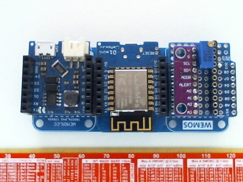
Two custom modules and the mini module were plugged into the tripler base shield as shown below
![]()
The output of the B0505 was connected to the 5 V rail. It was possible to connect the mini module to a PC because the Wemos mini was equipped with a diode placed between the Wemos mini USB connector and the 5 V power rail. Therefore the 5 V rail was driven by the B0505 and not buy the host PC. A button shield was placed on the top of the mini module in order to abandon execution of the server's code in the init.lua script if the button was pressed at the power up.
The following video shows that the readings of the ADC module were not adversely affected by the output ripples of the B0505 module. Please note that the web page was reloaded more frequently (every 300 ms) than the Wemos mini printed to the terminal (measurements were conducted every 200 ms but only one in ten was printed ). That is why some of the readings visible on the web page could be absent from the terminal log.
Next hardware revision will feature a custom mini shield with all the resistors, inputs and optional B0505. If it is not required or not available, the voltmeter can simply be powered from the always available Wemos mini USB connector losing the isolation though.
Overall, B0505 1W seems to be a perfect match for the IuT voltemeter requirements, both in terms of the power it can supply and the cleaness of its output voltage.
-
To pull or not to pull - that is the question
06/19/2017 at 23:15 • 0 comments... which turned to have the following short answer - to pull down with a 680 kOhm resistor. For a detailed answer
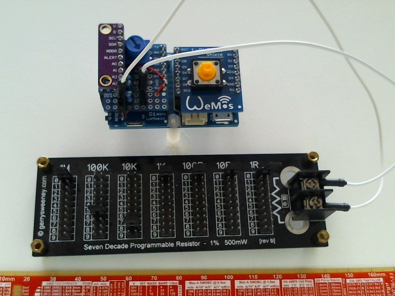
we need to acknowledge that a floating input of the ADS1x15 results in a rather high voltage reading. Therefore one either need low impedance driver at each input of the module (because the analog multiplexer is internal to the IC), which costs money and space, or a pull down resistor which value needs to be somehow optimised. I used an excellent programmable resistor as shown below.
![]()
(No affiliation with the maker, just bought one. To be frank that was the second time I used it but I believe if you do need one it is indispensable. There is also a3D printed case on Thingiverse which I only noted right now.
An alternative is an SMD kit to solder yourself where the resistance is programmed by clicking buttons. There are some other options as well.)
I used my_ads.lua module and changed ran and ch settings from the console when the resistor was connected in parallel to the relevant inputs. The following readings were recorded in mV for channel A0
ran 100k 250k 500k 1M 2M Open 0 7 18 32 56 98 570 1 8 21 41 76 133 570 2 4 16 33 61 103 277 3 9 30 59 100 148 269 4 0 0 0 0 0 0 5 0 0 0 0 0 0 The same readings for 2 MOhm pull down were observed for channels 1 and 3. The good news is that for any resistor tried the measured voltage was below the full scale limit at the highest gain. Therefore, if the automatic gain control is implemented and the input is left unconnected, the gain will increase until the reading becomes zero.
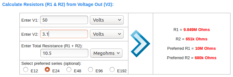
I did not try higher values for the following reason - to have a voltmeter that only measures to 3.3V is not sufficient for most uses. Therefore the final design will necessarily need an on board potential divider to measure voltages up to, say, 50 V. This voltage is safe to apply to an input directly, and is considered generally safe to humans although some exclusions do apply (link1, link2 and others). As the voltmeter has four channels, it makes sense to use resistor network (or array) which has four resistors in the same package. When I looked up networks available in single quantities from digikey.co.uk (are they sponsors of Hackaday or should I have been used Mauser instead?), the biggest value happened to be 10 MOhms. Using an online potential divider calculator, I have got the following resistor values
![]()
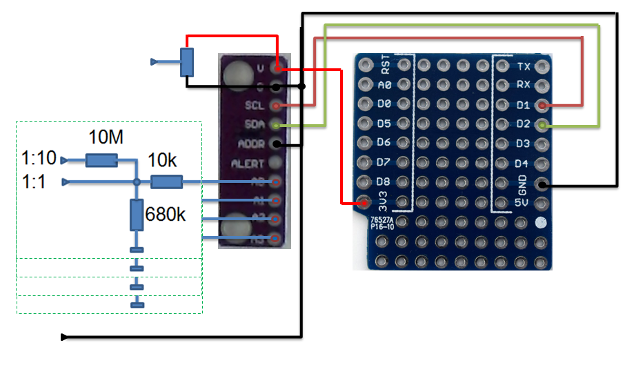
Consequently the final design will have three SMD resistor arrays of four resistor each with the values of 10k, 680k and 10M. The first array will be connected as shown on the schematic diagram in series with the ADS1x15 inputs. The other pin will be connected to the pull down arrays of 680k and turned pin headers for 1:1 inputs. The 10M array will be connected to the 1:1 inputs by one respective pin whilst the other pin will be connected to 1:10 turned pin headers. The dividers will be calibrated using voltages measured with high accuracy. The user will have an option to tick a checkbox for each channel where the wire is connected to the potential divider rather than to the regular 1:1 input.
![]()
Will need to assess whether to solder the additional resistors and sockets to the prepared custom Wemos mini shields or leave it for the final PCB design though.
-
Project tracker
06/17/2017 at 20:51 • 0 commentsI found out that too many things need to be properly noted even for this well defined little project.
These are
- features and options (completed)
- features and options under development and development alternatives
- to do later list (essential and non-essential features, options, refinements, cool things)
- things to revisit if time permits
- anything else
1. Features and options (completed)
- controlling and pulling out data from a ADS1x15 module using an ESP
- making an ESP operate as unencrypted access point
- serve a web page with dynamically hanging voltages
- self reload a page after defined interval (much smaller than a few seconds provided with meta refresh)
- operating over 4 hours from a single battery charge
- protecting the voltmeter from overvoltages up to 50 V
- stable voltage readings; accurate to 0.5%
- additional pull down resistors of 680k together with 10M ones will prevent erroneous readings from floating pins and extend the measured voltage range to 50 V DC which is generally considered a safe voltage for humans
- custom proto shield with a USB socket and isolated DC-to-DC converter to get rid of the battery and battery shield
- reliable way of getting NodeMCU firmware to the mini lite module was found (5A); these modules to be used instead of mini ones because of their lower height, cost and easier placement underneath the female headers on the tripler/dual bases
2. Features and options under development and development alternatives
- automatic gain control for measuring voltages (increases resolution for small voltages, Lua programming) - DONE but not yet reported
- connect READY pin of the ADC module to the Wemos mini; read ADC data on the interrupt; update measured voltage in the RAM and start a new single conversion for the next channel - DONE but not yet reported
- notify the user when the voltage is too close to Vdd of likely overload, which affects readings at all the channels (JavaScript audio alert) - change COLOUR?
- user selectable number of channels used and auto refresh interval (JavaScript dialog page)
- implement AJAX for updating voltage readings rather than page reloads (JavaScript programming)
3. To do later
- implement captive portal (when a station connects to the AP, the voltmeter page is loaded automatically). Worked example here. Seems like a cool feature for demonstrating the IuT voltmeter but a casual user can bookmark the IP address of the server not to type it over and over again. Interesting to try (Lua programming)
- custom shield to use with a LiPo battery without the overdischarge protection (got the module already)
- using an efficient buck converter to convert the LiPo battery voltage down to 2.7V, which should be enough for both the mini and ADC modules (the module is being delivered)
- custom PCB for ESP-12E (or some ESP8285-based ?) module (I have some required modules already)
- using segment display for the measured voltages (JavaScript programming required)
- add current measurement circuitry to the voltmeter. Worked example here (the relevant IC is being delivered; may require extra buffer to extend the current measurement range to some extent)
- add resistance measurement circuitry to the voltmeter. Worked example here (if the last two items are implemented, the voltmeter will become a fully featured DMM).
4. Things to revisit
- find out the optimal refresh rate depending on the number of connected clients, measurement channels used and power consumption
5. Anything else
A) Getting latest NodeMCU firmware to a Wemos Lite module using ESP8266Flasher (just follow the steps and do not ask why, this procedure did work for 4 modules I have this way)
- select SPI mode: Dual Out (DOUT) and 1 MB (8 Mb) flash size - required, lowering speed/flash frequency did not seem to help much
- flash the internal NodeMCU firmware first
- flash the later NodeMCU firmware with the size below 512 kB second
- finally flash the firmware you want that exceeds 512 kB in size
UPDATE: fully confirmed with two brand new modules; after each flash the module was connected to ESPlorer (9600 for the for first two flashes, 115000 for the last one) and operated normally. Mini lite modules are cheaper and lighter than the mini modules, and will be used for this project from now on.
B) implementing AJAX without a JS library/framework -
client_2_ESP
-
Test 2: performance
06/17/2017 at 17:51 • 0 commentsSome observations and test results
- protection
- consistency of measurements
- operation of the access point
- dynamically serving the web page
- operating the design from a single battery charge
- at last but not at least - how did the voltmeter measured voltages
The outcome - this is a voltmeter that underreports the measured voltages by 6 mV in the worst case at full scale measurement (below 0.5%).
1. Protection
worked well, 5V was tolerated at any pin for continuous time. The voltage drop at the protection resistor was found equal to Vin - Vdd = 0.806 V. The current through it was well within the specified limit for the ESD diodes 0.806V / 12 kOhm << 10 mA
2. Consistency of measurements
The device was powered from the 3.3V rail, which set the limit on the voltage to measure. 16 bit ADC should be capable of resolving 3.3V/2^16 or around 0.1 mV. As a switched mode power supply is used for converting the LiPo battery output to 5 V, one could expect the power supply riples affecting measurement consistency. These ripples were partially reduced by the on module linear voltage regulator, which converted supplied 5V into 3.3V. Additionally, as the voltage was displayed with the mV resolution, possible varitions in some less significant bits could not be observed. Finally, as the ADC operated using the sigma-delta (sigdel or delsig) principle, the input noise was effectively averaged over the measurement interval (measured at about 130 ms for a single shot measurement).
In practice measured voltages were stable over time. Sometimes, when the measured voltage was close to some integer number of mV plus half a mV, the last digit of the reading could fluctuate up and down by a single mV as it was expected.
3. Operating the access point (AP) in a busy 2.4 GHz environment
(no, I did not put the ESP into a microwave oven; do not to it either)The device showed up in a buzy environment (with 7 other WiFi networks operating at the same time) using the default WiFi channel. Two and even three stations connected to this AP operated without any major issues.
4. Dynamically serving the web page
The selected 300 ms interval for page reload worked for a long time for a single client. Two clients refreshing the page after 300 ms each worked together for a few minutes then one of these stuck waiting for the page from the server but the other kept going.
I put the client's time to the web page in the false hope to find the time the design could operate from the battery. I would note the time the operation started then note the last time displayed, and find the difference. Unfortunately this approach did not work for two reasons. First, despite the page was served reliably for over one hour when I kept an eye on it, the connection was lost over longer time intervals. Second, on many occasions the reloaded page was not received completely before the connection broke, and no time stamp was displayed.
I do not think it is a big problem if the user has to refresh the web page once in an hour though.
5. Operating time from a single charge of a 520 mAh LiPo battery
ESP8266, like any other WiFi transceiver, is power hungry. The measured transmit current is around 70 mA by several reports, which is the value stated in the datasheet. Additional power hogs for the Wemos mini system are the on module linear regulator that dissipates 1.7 V or 33% of the supplied 5 V, and the boost DC-to-DC converter that produces these 5 V out of the varied output voltage of the LiPo battery.
As it was discussed above, I could not measure the operating time the way I intended. Nevertheless, when the client was reconnected after several unmeasured timeouts, it was possible to load the web page after slightly over 4 hours then the AP disappeared.
6. Voltage measurement results
Finaly... Yes, this is essential for a voltmeter to measure voltages but I would call this project a failure if the IuT voltemeter did only this.
The following behavior was observed when using my ADC module's driver:
- if an input is floating, the measured voltage is 0.5788 V (0.577 mV for the ADS1015 module). If a multimeter is connected to a floating pin, the measured voltage fluctuates within 300..500 mV (either low impedance driver and/or a pull down resistor is to be used for every pin OR when the measured voltage equals to this value the user should be warned of possible float on this input - TODO)
- if there is an overvoltage at any of the inputs, the other readings are became affected too
ADC channel VinV, mV VinADC, mV Reading, mV 0 (5V pin) 4,753 3,947 3,827 1 (pot) 2,156 2,296 2,309 2 (Vdd) 3,290 3,287 3,402 3 (Gnd) 0 0,196 0,209 As you can see, there is no definitive relations among the measured voltages. If close to Vdd voltage is measured at any channel, the user should be warned (TODO).
- conversions in the single shot mode took 128-129 ms thus higher than 8 SPS data rates can be inaccurate
- measured volatges at different channels under normal operation
ADC channel VinV, mV VinADC, mV Reading, mV 0 (float) - - 0,579 1 (pot) 2,144 2,141 2,141 2 (Vdd) 3,291 3,287 3,285 3 (Gnd) 0 0 0
There is a small voltage drop at the protection resistor (3-4 mV) that needs to be accounted for accurate measurements. The measured voltage was understated by 2 mV at full scale measurement.
- the protection resistors' values (tolerance 5%) were measured on the custom shield as follows: 11.97 kOhm, 11.86 kOhm, 11.93 kOhm, 11.99 kOhm for channels from 0 to 3 respectively.
The outcome - this is a voltmeter that underreports the measured voltages by 6 mV in the worst case at full scale measurement (below 0.5%).
-
Functionality test 1: passed
06/09/2017 at 15:35 • 0 commentsHere is the video of IuT voltmeter serving a tablet with the reload interval of 300 ms
and the stress test - serving two clients simultaneously
-
Firmware 2 & web page : enabling basic functionality
06/08/2017 at 21:08 • 0 commentsThis log is about configuring the ESP for operating as WiFi access point (straightforward), enabling TCP server and programming relevant callback to serve dynamic web pages (learned a few new to me useful things), adding JavaScript code to reload the web page from the server automatically every 300 ms (my first practical use of JavaScript) and adding a script to start all the things on power up (init.lua).
I opted for unencrypted access point but provided all the available callback functions for debugging purposes (at some stage I would like to stress test the ESP AP capabilities by conncecting/disconnecting various stations). The first line loads ADC initialisation and measurement code discussed before
dofile("ads_module.lua")

-- wifi section - acess point, unencrypted with service callbacks

function wifi_conn(T)
  print("\n\tAP - station connected".."\n\tMAC: "..T.MAC.."\n\tAID: "..T.AID)
end
function wifi_disconn(T)
  print("\n\tAP - station disconnected".."\n\tMAC: "..T.MAC.."\n\tAID: "..T.AID)
end
function wifi_probe(T)
  print("\n\tAP - station probed".."\n\tMAC: "..T.MAC.."\n\tRSSI: "..T.AID)
end
function blank()
    return
end

wifi.setmode(wifi.STATIONAP)

cfg={}
cfg.ssid = "IuT_volt"
wifi.ap.config(cfg)

wifi.eventmon.register(wifi.eventmon.AP_STACONNECTED,wifi_conn)
wifi.eventmon.register(wifi.eventmon.AP_STADISCONNECTED,wifi_disconn)
wifi.eventmon.register(wifi.eventmon.AP_PROBEREQRECVED,blank)

tmr.delay(5000000) -- let it turn on first

print(wifi.ap.getip())
The following snippet creates and operates a TCP server via relevant callbacks-- net section - server html_st = 'p{text-align:center;font-size:60px}' .. 'var d=new Date();document.getElementById("demo").innerHTML=d.toLocaleTimeString();var myVar=setInterval(myTimer,300);' .. 'function myTimer(){window.location.reload()};' srv = net.createServer(net.TCP) srv:listen(80, function(conn) local response = {} conn:on("receive", function(conn, pl) --print("\r\n*** server received:\r\n"..pl.."\r\n*** end payload"); response = html_st; response = response .. rez .. ' V'; response = response .. '</p></body></html>'; conn:send(response) end) conn:on("sent", function(conn) conn:close() end) end) --srv:close()Dynamic web pages are created on the fly by displaying the ADC conversion rez along with the measurement units (V) on the page. The dynamic web page is prepared by concattenating the fixed header with the measured voltage and fixed footer. It reloads itself every 300 ms form the server by using JavaScript timer and reload method.The HTML/Javascript content of the page was first tested in a browser locally
<!DOCTYPE HTML>
<html>
<head>
<style>
p {
  text-align: center;
  font-size: 60px;
}
</style>
</head>
<body>

<p id="demo"></p>

<script>

    var d=new Date();
    document.getElementById("demo").innerHTML=d.toLocaleTimeString();
    var myVar = setInterval(myTimer, 300);
    function myTimer() {
        window.location.reload();
    }

</script>

<p>
<!-- Here will come the voltage from the ADC -->
</p>

</body>
</html>
that was later condensed by using a free online tool - HTML compressor for RAM savings. I considered placing the header and the footer into separate files, and reading these before serving the page but at this stage this potential RAM reduction was found unnecessary.I added provision for printing the time stamp in order to test for how long the voltmeter could operate from the battery. This provision was found useful to find whether the client is operating properly or is waiting for the response that will never come as the request was either not received or processed properly by the server. Some stress tests showed that the ESP can serve one client quite reliably but connecting two clients frequently caused dropped connections form one of these, not necessarily the same each time. (An ESP server can operate up to 4 clients simultaneously but this is complicated for the IuT_voltmeter because the ESP operates in the access point mode and the frequency of the requests is 6 per seconds for the two clients).
Finally, the lua.init file was to switch on the on-module LED when the module is reset, and if the poushbutton, connected to pin D3 (as it is done for the button mini shield), is not found pressed after 3 s, the IoT voltmeter starts its operation
print("init.lua started ...")
print("Hold the button NOT to start the code")

pin_in=3
gpio.mode(pin_in, gpio.INPUT,gpio.PULL_UP)
pin_out=4
gpio.mode(pin_out, gpio.OUTPUT)
gpio.write(pin_out,gpio.LOW)

tmr.delay(3000000)

gpio.mode(pin_out, gpio.INPUT,gpio.FLOAT)

if gpio.read(pin_in)==0 then
    print("\nDEFAULT MODULE DID NOT START - CANCELLED BY THE USER\n")
    gpio.write(pin_out,gpio.HIGH)
    return
else
    dofile('IuT_00.lua')
end
At this stage the hardware, firmware and web page became fully ready for testing.
-
Hardware - revision 2
06/08/2017 at 20:27 • 0 commentsThis revision was planned to have a trippler baseboard, a mini lite and a battery shield from Wemos, an ADC module (attached to the third base) all soldered to the baseboard in order to reduce the height of the device. However, following the experience with oldered battery shield for the revision 1, I decided to socket all these modules. As it turned out later, this was a wise provision to make.
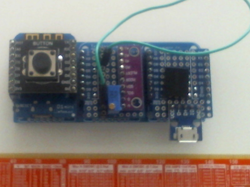
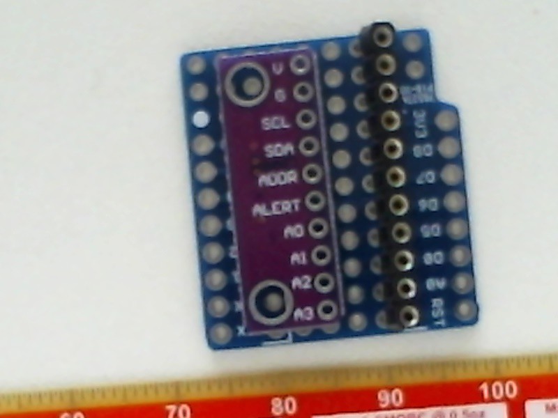
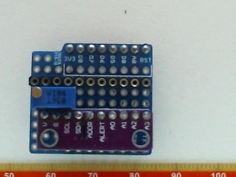
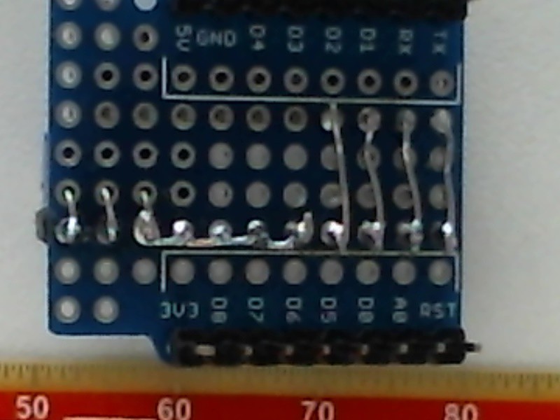
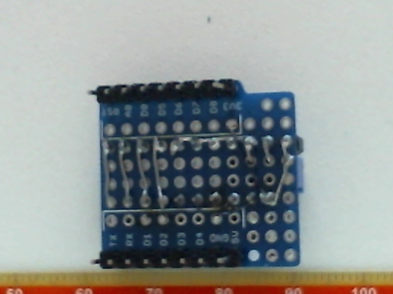
A new ADC shield was constructed first. It is hanging over the protoboard, supported by the four curent limiting resistors and held in place by soldered connections. This shield is not serviaceble or replaceable (unlike the one for revision 1) but has much lower height. Breadboard wires can be convenietly connected to either female pine headers (like in the revision 1), or to screw terminals (like in the photograph below)
![]()
or to turned pins header (which to some extent limits applicability of the voltmeter to other uses). In order to keep the height low the third option was selected for the revison 2:
layout before soldering
![]()
fully assembled shield, top view
![]()
partially soldered shield, view from the bottom
![]()
fully assembled shield, view from the bottom
![]()
Four pins on the right were soldered to the protection resisotrs' leads, the following four pins were grounded (you can never have enough ground pins, this is for sure), and three remaining pins were connected to the on shield potentiometer in this order ground, wiper, +3.3V. The potentiometer was added for the ease of testing and calibration of the voltmeter. The remaining connections were realised using solderable enamel insulated wire - it is almost invisible and thin. Unfortunately it is not easy for me to use it even for a few required connection although some people can do wizardry with it.
Socketing the shields brought about an obvious drawback of increased height of the prototype
![]()
![]()
So what was the benefit? It was nothing to do with the physical dimensions but it simply made it possible to continue with the development. Mini lite module should have been a cheaper and smaller option for the fully developed design comparing to the mini module. I have acquired two Wemos mini lite modules, one of which was soldered to stackable connectors and could be abused by inserting it incorrectly but the second was not soldered at all. I tried to flash the freshly generated firmware into both the modules using the NodeMCU flasher, making a compulsory change from default DIO to DOUT setting and 4MB to 1 MB in the Advanced tab (I laso lovered flash sped to 20 MHz just in case). The socketed module could take the firmware after a few attempts but the second one refused to accept any firmware bigger than about 500 kB (may be half of the flash became unusable for some reason or could not be written to by the NodeMCU flasher ?). I also noticed that both the ESP and the on board voltage regulator were running very hot indeed. May be this was the reason for intermittent stoppages of communication between the ESP and the ADC shield. Unfortunately Wemos did not released the schematic of mini lite module yet, and it is difficult to say whether this behavior should be attributed to some my misunderstandings or ignorant actions, design oversight, components working outside of their specified operating conditions or being faulty, assembly mistake(s) etc. (Maybe the battery shield is not even compatible with the mini lite?)
Not soldering the mini lite module allowed me simply to insert a mini module instead, and complete the development of a completely prototyped device. I may want to revisit flashing and operating the mini lite shields in the future but for now I am sticking to Wemos mini modules.
Therefore the hardware used for finalising firmware and web page developments looked as follows
![]()
Final warning - do not forget to unplug the programming USB cable from the mini module before plugging the battery (or USB charger cable) into the battery shield.
-
Firmware 1: how to stop worrying and reinvent the wheel
06/04/2017 at 20:07 • 0 commentsI was not afraid of writing driver code for the ADC module, and I did. When I later built the NodeMCU firmware, I found that this driver was already written and available for inclusion. Nevertheless using such a driver would be difficult without reviwing the ADC datasheet, and I did not worry too much for reinvenbting the wheel. Hence the title of this log.
Note 1 : why NodeMCU firmware (Lua interpreting language) was selected for this development
The ADS1x15 driver was developed on top of the i2c module available from the NodeMCU firmware build.The code checks the presence of the i2c module in the build first
-- check presence of the i2c driver
if require('i2c') then
    print("i2c driver present; execution continue")
    -- otherwise the LUA interpreter flags an error
end
After that some variables are initialised with particular values to refer to these values by name (interpreting languages do not support C-like #define)
-- DEFINE section - constants to use
-- NodeMCU specific
id_i2c = 0  -- not to get confused with compulsory 0 in the code
-- WEMOS mini specific
sda = 2 -- SDA line on the i2c WEMOS mini shields
scl = 1 -- SCL line on the i2c WEMOS mini shields
-- ADS breakout board default
ads1x15=0x48 -- connection on the breakout board
-- ADS operating ranges (datasheet table 8 p. 26)
ranges = {6.144,4.096,2.048,1.024,0.512,0.256}
Three high level functions operate the ADC as specified in its datasheet; these must be presented to the Lua interpreter before the first call
-- THREE ADS DRIVE FUNCTIONS
-- ADS driver function - start a singe conversion
-- ch 0..3 (MUX), ran 0..5 (PGA)
-- datasheet ADS1x15 p.26, table 8
function ads1x15_single_start(id_i2c,dev_addr,ch,ran)
    i2c.start(id_i2c)
    tmp=i2c.address(id_i2c, dev_addr, i2c.TRANSMITTER)
--
    i2c.write(id_i2c, 0x1) -- select the CONFIG reg then write to it
--
    -- 1xxx xxxx  start a single conversion = 8 (0 for continuous)
    -- x1xx xxxx  single ended mode = 4
    -- xx?? xxxx  channel from the user
    -- xxxx ???x  measurement range
    -- xxxx xxx1  single shot mode
    i2c.write(id_i2c, (8+4+ch)*16+(ran*2+1) ) -- MSB
--
    -- 000x xxxx  lowest data rate (applicable for continuous mode)
    -- xxx0 xxxx  comparator mode - traditional (default)
    -- xxxx 0xxx  comparator polarity - active low (default)
    -- xxxx x0xx  non-latching comparator action (default)
    -- xxxx xx11  keep RDY pin in high-impedance state
    i2c.write(id_i2c, 0x03 ) -- LSB
 --
    i2c.stop(id_i2c)
--
    return tmp -- the device should acknowledge its address
end
-- ADS driver function - check that singe conversion is completed
function ads1x15_not_ready(id,dev_addr)
    i2c.start(id_i2c)
    tmp=i2c.address(id_i2c, dev_addr, i2c.TRANSMITTER)
    i2c.write(id_i2c, 0x1) -- select the CONFIG reg
    i2c.stop(id_i2c)
-- read it
    i2c.start(id_i2c)
    tmp = i2c.address(id_i2c, dev_addr, i2c.RECEIVER)
    tmp = i2c.read(id_i2c,2)
--
    i2c.stop(id_i2c)
    if (string.byte(tmp,1)<128) then
        return true
    else
        return false
    end
end
-- ADS driver function - read the last conversion's result
function ads1x15_read(id,dev_addr)
    i2c.start(id_i2c)
-- select the CONVERSION register
    tmp=i2c.address(id_i2c, dev_addr, i2c.TRANSMITTER)
    i2c.write(id_i2c, 0x0) -- pointer to the CONFIG reg
    i2c.stop(id_i2c)
-- read it
    i2c.start(id_i2c)
    tmp = i2c.address(id_i2c, dev_addr, i2c.RECEIVER)
    tmp = i2c.read(id_i2c,2)
--
    i2c.stop(id_i2c)
    return tmp -- string of two bytes is returned
end
-- ADS driver function - init the device
function ads1x15_reset(id,dev_addr)
    i2c.start(id_i2c)
-- select the CONVERSION register
    tmp=i2c.address(id_i2c, 0, i2c.TRANSMITTER)
    i2c.write(id_i2c, 0x06) -- code for power down mode p.21
    i2c.stop(id_i2c)
--
    return tmp -- string of two bytes is returned
end
Next comes the code to initialise the driver and the ADC ( what is called setup() in Arduino programming )
-- setup and check the soft i2c peripheral
i2c.setup(id_i2c, sda, scl, i2c.SLOW)
print("SDA = ",gpio.read(sda)) -- check it is 1 (line pulled up whilst idle)
print("SCL = ",gpio.read(scl)) -- check it is 1 (line pulled up whilst idle)
print("ADS reset = ",ads1x15_reset(id_i2c,ads1x15))
-- test case
ran=1
ch=1
-- when the code executes, change at will in the terminal
Finally, the following code, when presented to the interpreter, causes voltage measurement on a single defined CH pin using set RAN every 3 seconds with proper ADC readiness and presence checks. In addition, it measures the conversion time, prints raw bytes received from the ADC, and handles the issue of negative measured voltages (MSB is set in the returned data; NodeMCU/Lua seems not to support signed 16-bit integers).
-- measure each 3 seconds
tmr.alarm(0,1000,tmr.ALARM_AUTO,
    function ()
        if ads1x15_not_ready(id_i2c,ads1x15) then
            print("ADS1x15 has not finished a conversion")
            return
        end
        tmp=ads1x15_single_start(id_i2c,ads1x15,ch,ran)
        if tmp then
            print("")
        else
            print("ADS1x15 does not respond")
            return
        end
        t1=tmr.now()
        while ads1x15_not_ready(id_i2c,ads1x15) do
            tmr.delay(1000)
        end
        print("Convertion took > ",tmr.now()-t1," us")
        rez=ads1x15_read(id_i2c,ads1x15)
        print("Raw bytes = ",string.byte(rez,1,2))
        if string.byte(rez,1)<128 then
            print("Reading, V = ",(string.byte(rez,1)*256+string.byte(tmp,2))*ranges[ran+1]/32768)
        else
            print("Reading, V = ",((string.byte(rez,1)-255)*256+string.byte(tmp,2)-255)*ranges[ran+1]/32768)
        end
     end
)
When the code is running, one can change CH and RAN from the console, getting instant measuremnent results without the need to recompile the whole code. The code starts ADC measurement and checks whether it is completed every 1 ms; the typical value was found around 140 ms which was commensurate with the slowest sampling rate of the ADC of 8 samples per second.
Using the built in ADS1015 module makes the code more compact (but some of the constants may still look cryptic)
-- check presence of the ads1115 driver
if require('ads1115') then
    print("ads1115 driver present; execution continue")
    -- otherwise the LUA interpreter flags an error
end

-- DEFINE section - constants to use
-- NodeMCU specific
id_i2c = 0  -- not to get confused with compulsory 0 in the code
-- WEMOS mini specific
sda = 2 -- SDA line on the i2c WEMOS mini shields
scl = 1 -- SCL line on the i2c WEMOS mini shields
-- ALERT pin of the ADC is not used at present
-- module's constants were put into arrays for ease of alterations
ranges={
         ads1115.GAIN_6_144V, -- 2/3x Gain
         ads1115.GAIN_4_096V, -- 1x   Gain
         ads1115.GAIN_2_048V, -- 2x   Gain
         ads1115.GAIN_1_024V, -- 4x   Gain
         ads1115.GAIN_0_512V, -- 8x   Gain
         ads1115.GAIN_0_256V  -- 16x  Gain
}
channels={
        ads1115.SINGLE_0, -- channel 0 to GND
        ads1115.SINGLE_1, -- channel 1 to GND
        ads1115.SINGLE_2, -- channel 2 to GND
        ads1115.SINGLE_3, -- channel 3 to GND
        ads1115.DIFF_0_1, -- channel 0 to 1
        ads1115.DIFF_0_3, -- channel 0 to 3
        ads1115.DIFF_1_3, -- channel 1 to 3
        ads1115.DIFF_2_3  -- channel 2 to 3
}


-- setup section
i2c.setup(id_i2c, sda, scl, i2c.SLOW) -- set up the i2c controller
ads1115.setup(ads1115.ADDR_GND) -- ADR to GND connection for the i2c address 0x48
ran=0
ch=0
rez=0.
cnt=0

tmr_adc = tmr.create()
-- measure each 200 ms
tmr_adc:register(200, tmr.ALARM_AUTO,
    function()
        -- single shot setup
        -- data rate stated for correct timer callback setting
        ads1115.setting(ranges[ran+1], ads1115.DR_8SPS, channels[ch+1], ads1115.SINGLE_SHOT)
        -- start adc conversion and get result in callback after conversion is ready
        ads1115.startread(
            function(volt, volt_dec, adc)
                rez = math.floor(volt)/1000
                cnt = cnt + 1
                if cnt>10 then
                    cnt = 0
                    print('Voltage = ' .. rez .. ' V')
                end
             end
        )
    end
)
tmr_adc:start()
--tmr_adc:stop()
This code was used for the complete design - it starts mesuring voltage from the single ended channel A0 of the ADC every 200 ms then reads the ADC converted voltage using callback mechanism after a particular delay. It outputs to the console one in ten measurements only in order to give a chance to other pieces of firmware outputting their diagnostic messages. (Note 2: how do the drivers handle delays for ADC conversions.)The latter code was used for the first prototype.
Note 1: why NodeMCU firmware (Lua interpreting language) was selected for this development
A few words regarding the choice for firmware development. At the moment one can develop for ESP using Arduino ecosystem, AT commands, Basic, native C (C++), Espruino (JavaScript), microPython, NodeMCU (Lua) - this alphabetical list may not be exhaustive. All of these options were developed, supported and used for projects by a number of smart and inspirational people. My background is with embedded development and not computer networking. For this reason I personally found it easier to use NodeMCU as this was the first open and comprehensive interpreting system with zero cost software toolset. (Espruino and microPython came later, I supported development of both through Kickstarter as I do believe people with other background would benefit from these.) The advantage of interpreting environment is that you do not need to wait a couple of minutes to compile the code then some time to program the flash code memory; instead you can type your instructions and get instant feedback. I did require this option when I tried to figure out how to operate, for example, a UDP listener. The drawback of interpreters is the need to store a substantial code that taxes resources of the computer system, and slower execution because the interpreter needs to process any repeated instructions every time they need to be executed. A perfect combination would be to use an interpreter for debugging then compiler for deployment but this combination does not seem to exist for the ESPs. For the above reason this development was conducted using NodeMCU firmware (Lua interpreter built on top of the Espressif SDK + optional custom modules).
An added complication for using NodeMCU/Lua is its RTOS-like behavior. Howevre this feature may became a serious advantage when developing a real application.
Of course there are other compliucations, four of which are discussed here.
Note 2: how do the drivers handle delays for ADC conversions
My driver checks whether the last conversion was completed then reads the data. ADS1115 driver simply reads the ADC's output register after a set delay. For this reason it is important to state the data rate that sets a delay which is long enough to complete the conversion, i.e. ADS115.DR_8SPS .
TODO: the ADC can report completion of the present conversion via its ALERT pin. By connecting this pin to an unused Wemos mini pin one can trigger an interrupt then the callback function will simply need to read the converted value.
IuT voltmeter for a breadboard
Measure several voltages on a breadboard and display results on a smartphone for less than $10 for parts