-
Bug hunting and a look back
11/14/2014 at 02:55 • 0 commentsI took the boat for a test run and discovered some stuff about the new code. It's quite reliable (as long as the XBees are within range of each other), and the lag problem has been fixed. However, there's some weird bugs, but what can you expect?
First and foremost, when attempting to run the boat at full throttle, for no apparent reason, the boat will only move at a slow speed. If you move the joystick to just the right place, though, it will run much faster. I'm not sure if this is being exhibited by the ESC or not. It could be normal behavior, but this is unlikely-the ESC was intended for airplanes, and behavior like that could cause the plane to crash. I might be trying to output servo values that the ESC is misinterpreting. I'll have to poke around with the code and see what happens. I'm not sure if the problem's in the old code-I'll have to test that.
The other bug is also quite weird: once lit, the debug LED will never turn off on the controller. I have no idea why this is happening, so I can't give any commentary here.
There are some choices I regret making in this project-and some things that happened that were just plain funny.
- At first, I ordered two breadboard-style PCBs: one for the boat, and one for the controller. I was terrible at soldering back then, and I ruined many of the traces on the board. Oops. Oh well-the ruined board was too big for the controller, anyway. The one in the boat wasn't so bad, and it's still sitting in there.
- Originally, when I soldered up the transmitter PCB, I had added a 7805 for power regulation. Initial testing proved it to be okay, but I realized later that the 7805 had begun smoking, and the power LED was lighting even with the switch off. To top it all off, I made the fatal mistake of touching the 7805 to see just how hot it was. Not a good idea. I was a newcomer to electronics then, so that spooked me a bit, so I didn't work on the boat for a while after that. I'm still not sure why that 7805 was smoking.
- I eventually desoldered everything from the bad board except a pullup resistor, a reset switch, and the 28-pin ATMega socket. The board didn't look so good after all the rework. Sorry about the image quality-I didn't feel like getting out my regular camera, so I cheated and used a webcam.
![Awful soldering made worse by low resolution.]()
- Also, the iron I started with wasn't that powerful and came with lead-free solder without flux...ugh. Sure, it's RoHS compliant, but it can be a pain to work with when your iron isn't powerful enough and you're just starting out.
- I never bothered adding an external programming header to the transmitter-I could just open it up, disconnect the radio and the other headers, and program it, right? Not a good idea-it turns out, I often end up having to disconnect everything, then reconnect it all again, disconnect, reconnect, just for one iteration of code. Annoying.
- I didn't plan out the wiring that well in the transmitter-there are three cables running between the halves (and one of them is just a single wire for the debug LED-ground runs through another cable), and there are a couple more just for the back half. Also, the power cable running to the switch and back is too short and tends to unplug itself when you lay it open to work on the inside. I would have just used one ribbon cable in hindsight, but oh well. Also, I'd probably have to use a separate pair of 22 gauge wires for power (due to the way the Arduino Pro Mini regulates power, the switch has to be connected to the 9v line in from the battery pack).
- The Air Hogs controller is a bit cramped and hard to work with, but it's got a nice huge 9 volt battery holder in there. Nope, not a 9v battery, but 6 AAs! Heavy, but they'll last forever. Also, I got free shoulder buttons!
- Someone I was working with on this project put some Mod Podge to try and waterproof the paint on the side of the boat (we weren't sure if it was water-soluble or not). It turns out, Mod Podge is sticky when cured, and some got on the bottom of the boat. We're careful to store it propped up now so it doesn't stick to whatever it's sitting on, but it's annoying. Oh well.
- The Parallax breakout for the analog stick has been hacked with thin wire so many times-I almost wonder why it's even still in there. Sure, it has nice mounting holes, but that's what hot glue and perfboard is for.
- Originally, I put a nonstandard ISP connector without +5v and GND on it on the boat receiver board (I still didn't have an FTDI breakout then). I ended up desoldering that and putting an FTDI header in the same place. On top of that, all the rework stressed out the board, so some of the traces have lifted. At least it's still holding out.
Does anybody have any ideas why my code is behaving strangely? Also, swapping the XBee out for the programmer is quite annoying on the boat end-I also have to disconnect the ESC, which normally provides power to the boat to protect the battery and regulator. Does anyone know of a better way?
-
Motoring along...CRASH!
10/05/2014 at 20:16 • 0 commentsJust a quick note-I've literally run into a wall with this project. While doing a dry land test, I fractured the plastic on the corner of the boat. (Mental note-must learn to drive better!) Since the plastic is just a coating on top of a foam base, it probably wasn't as strong as it could have been. The boat is officially grounded until repairs are made. I'm hoping I can get this fixed soon. Fingers crossed.
PS-To all of you following or just browsing this project page, do you have any suggestions on how to redo the corner? I have the old pieces, but I'm considering just filling it over with more liquid plastic instead of supergluing the old pieces in place. Are there any other modifications or add-ons I should make? I'd love to have some additional feedback to help this project grow. Thanks!
-
Motoring along
09/27/2014 at 22:00 • 0 commentsEDIT: Whoops, where'd the picture go? I've fixed that.
I've finally gotten around to typing a new project log. I've got a lot to tell you, so let's get started.
First of all, the boat took its maiden journey (admittedly, a while ago) in a small construction pond. Of course, I had to repair the loose wire on the motor. As expected, steering was a bit clunky, and there were code glitches (full motor speed sometimes causes it to stop moving entirely). Still, it was good. Except for the part where the loose wire broke. Again. Since then, the boat has been put aside...until now!
Now for the new changes. Take a peek!
![]()
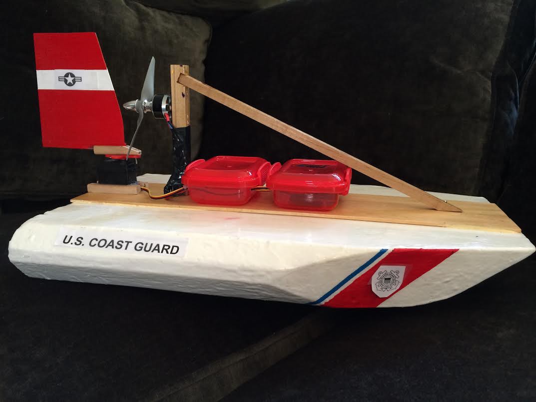
The decals are temporary-I haven't gotten around to getting proper decal paper to make them look nice. They've been added along with the new paint job (thanks, U.S. Coast Guard boats for looking so cool!) Also, the rudder (technically, vertical stabilizer) has been beefed up for better control. Also, I've fixed one of my biggest problems: the motor!
As you can see from the parts list, I have upgraded the motor to a more powerful model, with the added advantage of a better propeller mount and a better motor mount. Yay, no more vibrations! Also, the wires are affixed better, so I don't think I'll have to worry about magic smoke anymore. I'm using the same ESC as before, so I have to be careful not to overload this motor or I might damage the ESC. Also, I had to put bigger bullet connectors on the ESC's cable harness-they were sized for the smaller motor and wouldn't fit the larger one.
The old motor was fixed after the maiden voyage, but I still got magic smoke out of it. Also, a guy at my local hobby shop notified me that my propeller was on backwards. That probably was affecting the speed of the motor (and thus the boat).
So! The boat is finally ready for another test. What next? Hmmm....a Hackaday decal somewhere? Nose camera? The possibilities are endless!
Oh, I forgot to mention. Thanks to the new motor, it's now strong enough to push itself (slowly) over carpeted flooring. Score!
-
Communications update
08/30/2014 at 12:22 • 0 comments*EDIT* Whoops, almost forgot! The new code is in the project files folder, along with the old code for reference.
It's time for me to get rid of my old, bloated communications system and replace it with a faster alternative.
My old system would constantly send 5 byte packets:
- Start of packet
- Analog joystick X
- Analog joystick Y
- Left digital trigger
- Right digital trigger
This is a horribly bloated system. Even if a parameter's value doesn't change, it still wastes time sending the old value. Also, the triggers are digital buttons and can be consolidated into a single byte. To save time, I changed the protocol to send 3 byte packets:
- Start of packet
- Parameter to modify
- New value for parameter
The command-data 2 byte system (thanks, Quinn Dunki for the idea!) allows me to send only the values that change. I can also set an order of importance on the controller's end: if multiple values change, I can set which parameter will be updated first. It would be good if I could get rid of the "start of packet" byte, but that introduces problems related to synchronizing the controller with the boat and making sure that parameter bytes aren't interpreted as data bytes, or vice versa. This system uses one extra byte to save a lot of time and code, and it makes for a pretty bulletproof system.
There is one fault with a system like this. Suppose the boat is moving away from the controller. In order for the boat to move, the brushless DC motor must be on. If the boat loses connection with the controller, it will finish parsing the last byte received and wait until another byte is sent.
Hmm...wait a second. If the boat doesn't get another byte from the controller, it'll just leave the motors at their current positions until they are updated. If the boat is out of range, that will never happen, and the boat will just keep motoring along. To complicate things, the boat was going away from the controller in the first place. See the problem?
My solution is to implement a software watchdog timer (I had problems getting the hardware watchdog timer interrupt to work). When a command is received on the boat, the time in milliseconds after startup is recorded. After checking for a command (and parsing it if necessary), the boat will compare the current time in milliseconds after startup. If it is more than a second later than the time the last command was received, it'll stop the brushless DC motor to save battery life and prevent it from motoring away from the user. Unfortunately, it's not smart enough to motor back to the user-that would be nice, but I don't have the right set of sensors and components to implement that.
What's next? Replacing the brushless DC motor. After all, my lab is a no-smoking zone. Wait, does the soldering iron have to go, then? Oh, great, I tried to make a joke and it backfired on me. I'll end this project log here to save me from further humiliation.
-
Ongoing fixes, ongoing problems
08/26/2014 at 02:02 • 0 commentsAgain, I've run into another roadblock in the course of this project.
First of all: the communications glitch has been solved. Here's the technical lowdown.
My code has a simple communications protocol:
- Send a "~" to signal the start of a packet
- Send a byte for the analog joystick's X position
- Send a byte for the analog joystick's Y position
- Send a byte for the status of the left digital trigger
- Send a byte for the status of the right digital trigger
I know, I know, the two trigger bytes can be merged for speed. I'm working on that. For now, I just want communications to work.
This is implemented fairly easily. The bug, however, came from poor planning. I put some simple code in the receiver to wait for data to arrive in the serial buffer before beginning to process a new packet. Once data arrives, the code checks that the first byte is a tilda ("~"). If so, then it reads four bytes, processes them, and sends the data out to the motors. If the first byte isn't a tilda, it will keep checking each incoming byte until it gets a tilda. See the problem?
The bug came from my code waiting for data to arrive in the serial buffer. I was waiting for any amount of data, no matter how big or small. In doing so, I overlooked this fact: just because data has arrived doesn't mean the entire packet has finished transmitting. Because of this, the code was trying to process an incomplete data packet. The processing code would finish before the packet completely arrived, returning a -1 (no data) code for each "ghost" byte. Once it finished, the loop would see more data in the buffer: the rest of the broken packet. The tilda ("~") check would fail, and the loop would keep checking incoming bytes until it found the start of the next packet. There still wouldn't be a full packet in the buffer, so the cycle would continue, breaking the communications scheme.
The fix: The buffer now waits for at least 5 bytes: a full packet. Simple, huh?
Before this code update, I also had a newline byte sent to mark the end of a packet. With the XBee's onboard redundancy and the tilda already there, I found this to be a waste of time, so I removed it. Instant speed boost!
However, with every fix comes another gotcha. In this case, it was a hardware problem. When testing the new code, I found that the brushless motor wouldn't turn. Instead, it jittered in place.
Quick side note on how brushless motors of the type I use are driven:
The motor has three sets of electromagnetic coils that turn the shaft. They must be energized in the right order in order for the motor to turn. This is handled by a brushless ESC (electronic speed controller). This is driven in the exact same way as a servo motor, but 0 degrees (on a normal servo) corresponds to "off", and 180 degrees corresponds to "full throttle". Since this ESC has a built in BEC (battery elimination circuit), it also connects to the Li-Po battery and regulates +5 volts to power the receiver.
I believe that the motor's coils were being energized in the wrong order, causing the jittering back and forth. When I tried to diagnose it, I first tested my receiver (the most custom thing in the system) with the basic Arduino "sweep" test program. It produced the same symptoms and a problem: at full power, the motor began to smoke. I'm not sure why this happened, but it seems to have partially broken the motor. The startup beeps (generated by the ESC and produced by the motor vibrating) are very quiet, when they should be quite loud. I'm not sure where the original fault came from: the ESC improperly driving the motor, or the motor itself. The funny thing is, it was working fine when I had to use the setup for a completely separate demonstration. The only difference was the receiver/controller: I was driving it off of an Arduino UNO. That shouldn't affect the setup, though. Right?
So, as of now, I'm stuck. I think the next step will be to see if the ESC or the motor needs to be replaced, and if so, which one (or both). I'm curious to know why the motor started jittering, since the same setup I used worked in the past. Does anybody know out there?
Note: I also made some progress on the boat assembly. I'll post about that soon.
-
Boat assembly, part 1
08/14/2014 at 22:22 • 0 commentsI've begun to assemble the boat from individual parts into a whole unit.
Note: Apologies in advance for the grainy photos-I was taking these at night, and the lighting is horrible where I was assembling it.
![]()
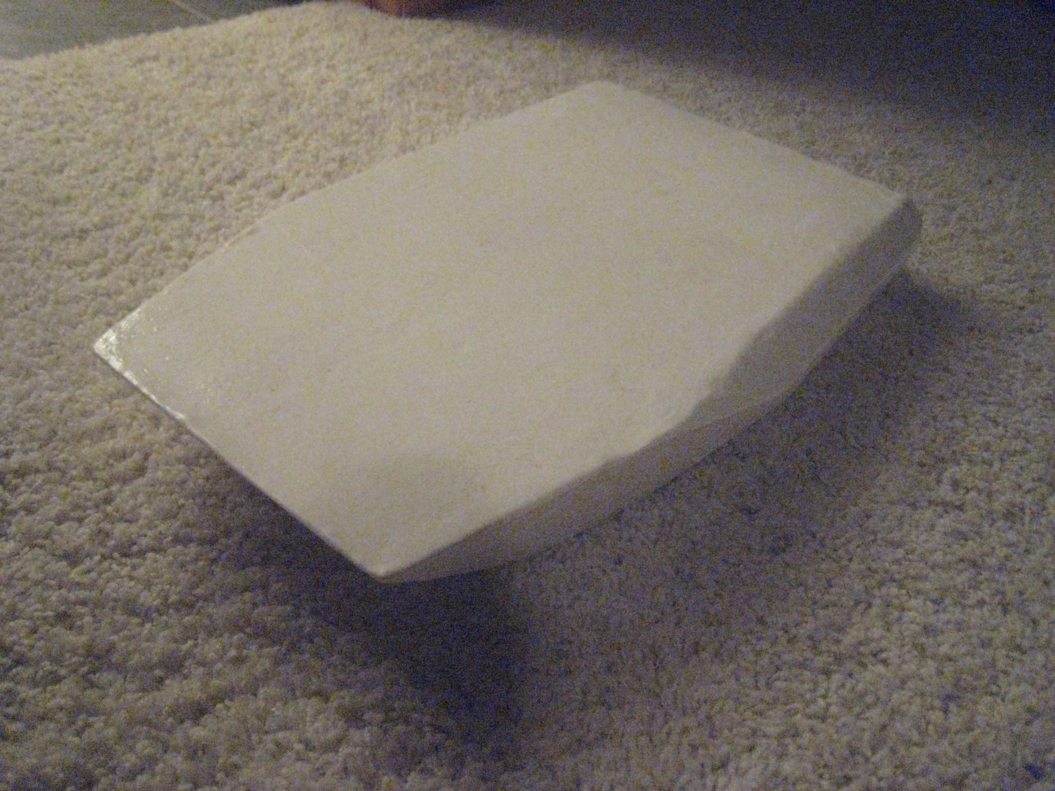
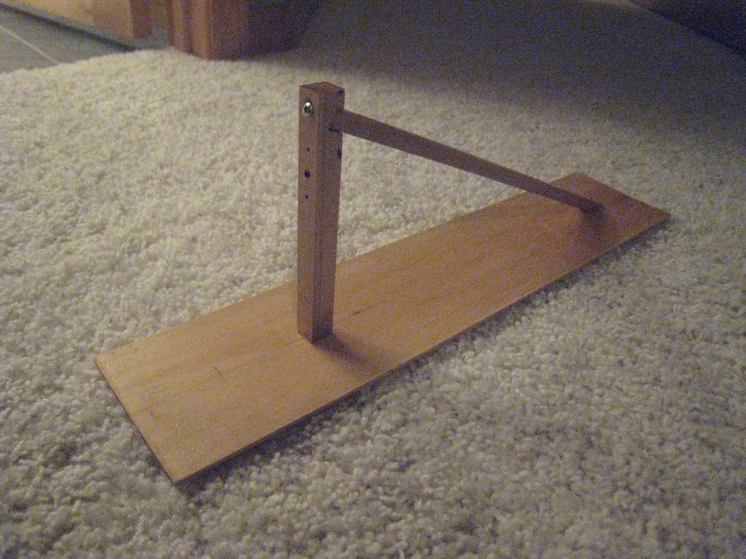
This is the boat base, originally cut from foam and coated in plastic. It's quite stable, and I'm planning to add a fin on the bottom for turning stability. These two parts are the frame that will contain the electronics and motors. They've been varnished with a marine varnish, so they're water-resistant to some degree. They won't survive being dunked underwater and soaked, but the occasional splash won't hurt them.
![]()
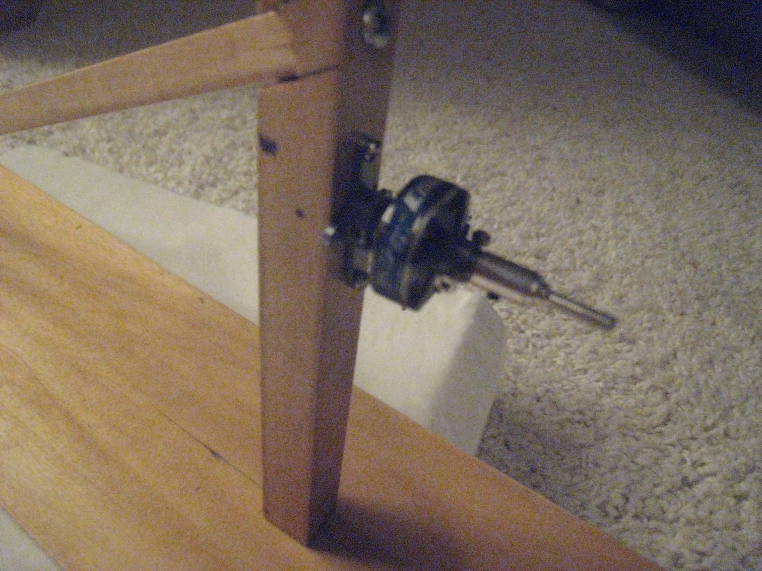
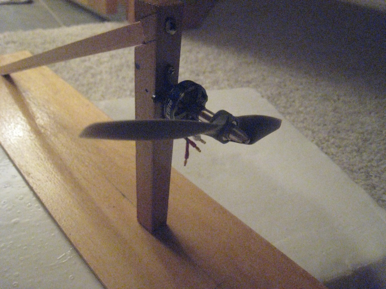
After assembling those two parts, I mounted the main motor and propeller. This went fairly easily, except for the fact that the varnish leaked into my screw holes and filled them. Luckily, the varnish is relatively weak, so I was able to screw through it and fix the motor in place.
![]()
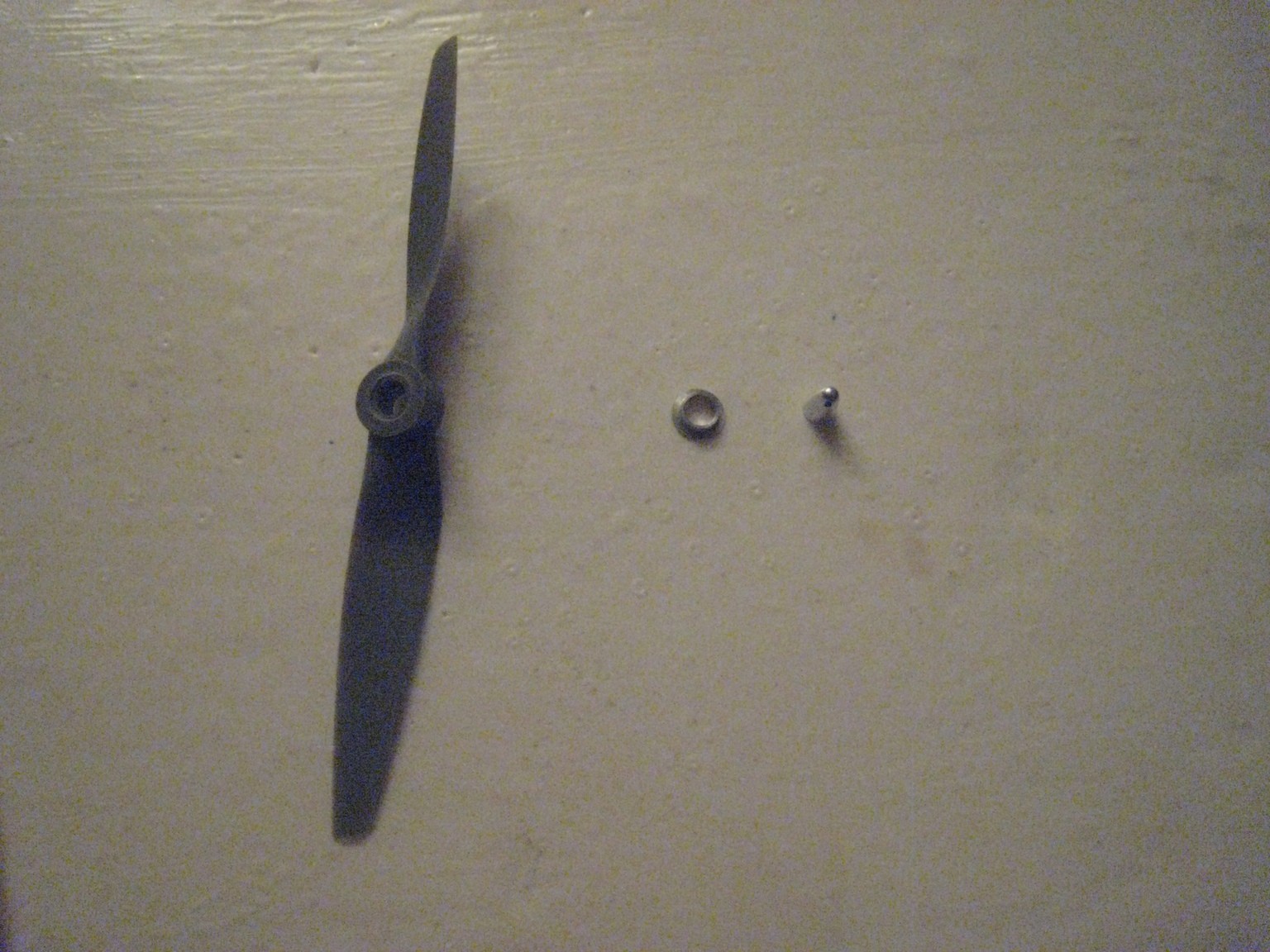
The propeller, surprisingly, is not screwed in place. Instead, it slips (loosely) onto the motor shaft, followed by an adapter ring and the end cap. The adapter ring adapts the wide opening of the propeller to a smaller opening able to be clamped onto by the end cap. The end cap has threads that screw onto the main motor shaft, squeezing the propeller into place.
![]()
![]()
What's left? I have to mount the electronics and the servo motor onto the boat, and the wood structure needs to be mounted to the base. Stay tuned for future updates!
-
The current state of (mis)communications
08/11/2014 at 03:58 • 0 commentsAs of now, this project has bumped into a minor problem: the radio transmission system has stopped working. Data is being transmitted via the XBee modules, but the ATMegas are not understanding each other. I will have to look into the code (which I will post soon) and check if the transmitter and receiver code both implement the protocol correctly. While I am at it, I should redo the protocol: it's quite bloated and has lag issues. The XBees are sending and receiving; I have verified this using an XBee Explorer from SparkFun.
While this is being fixed, I still have to work on the boat final assembly. The foam base is ready to be affixed to the electronics platform: a wooden board running lengthwise across the foam. This will be assembled using a "glue and screw" technique for the best adhesion possible. I'm using some small plastic food containers from the dollar store to hold the electronics and keep them dry. This is especially important for the Li-Po battery. Two separate containers are used: one for the battery, and one for the receiver. The battery is relatively heavy, and this must be placed in the center of the boat to prevent tipping. I also have to find room for the receiver container alongside that (though it is light, placing it on the side would still tip the boat a bit and potentially steer the boat in one direction), and space is tight underneath the brace for the propeller-pole.
After this is finished, I will be able to finally test it and start adding cool features (expansion port for sensors?).
DIY Airboat and Controller
A small, flexible boat and controller system able to travel where a standard boat could not go.
 CompuCat
