-
Home etching
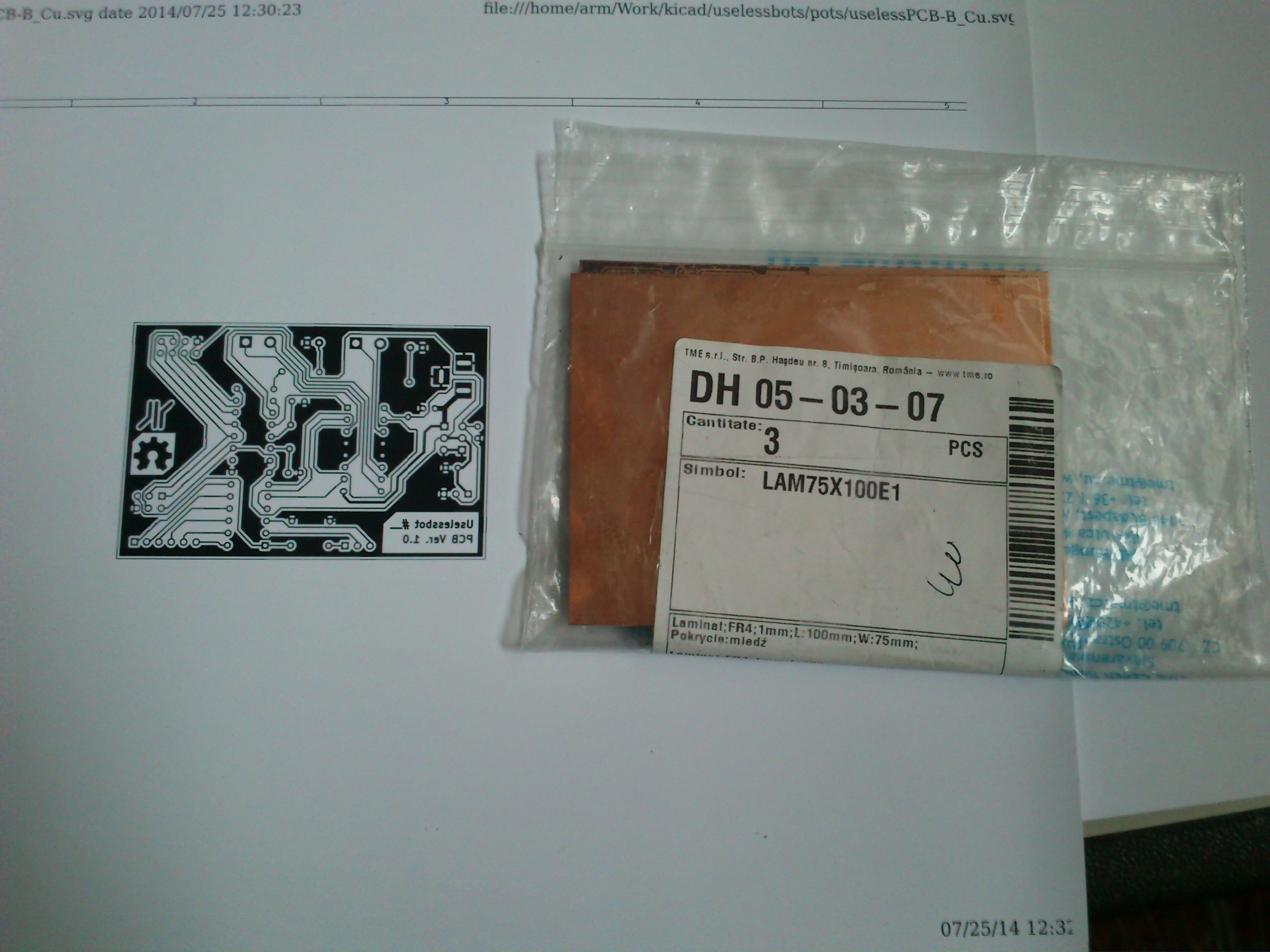
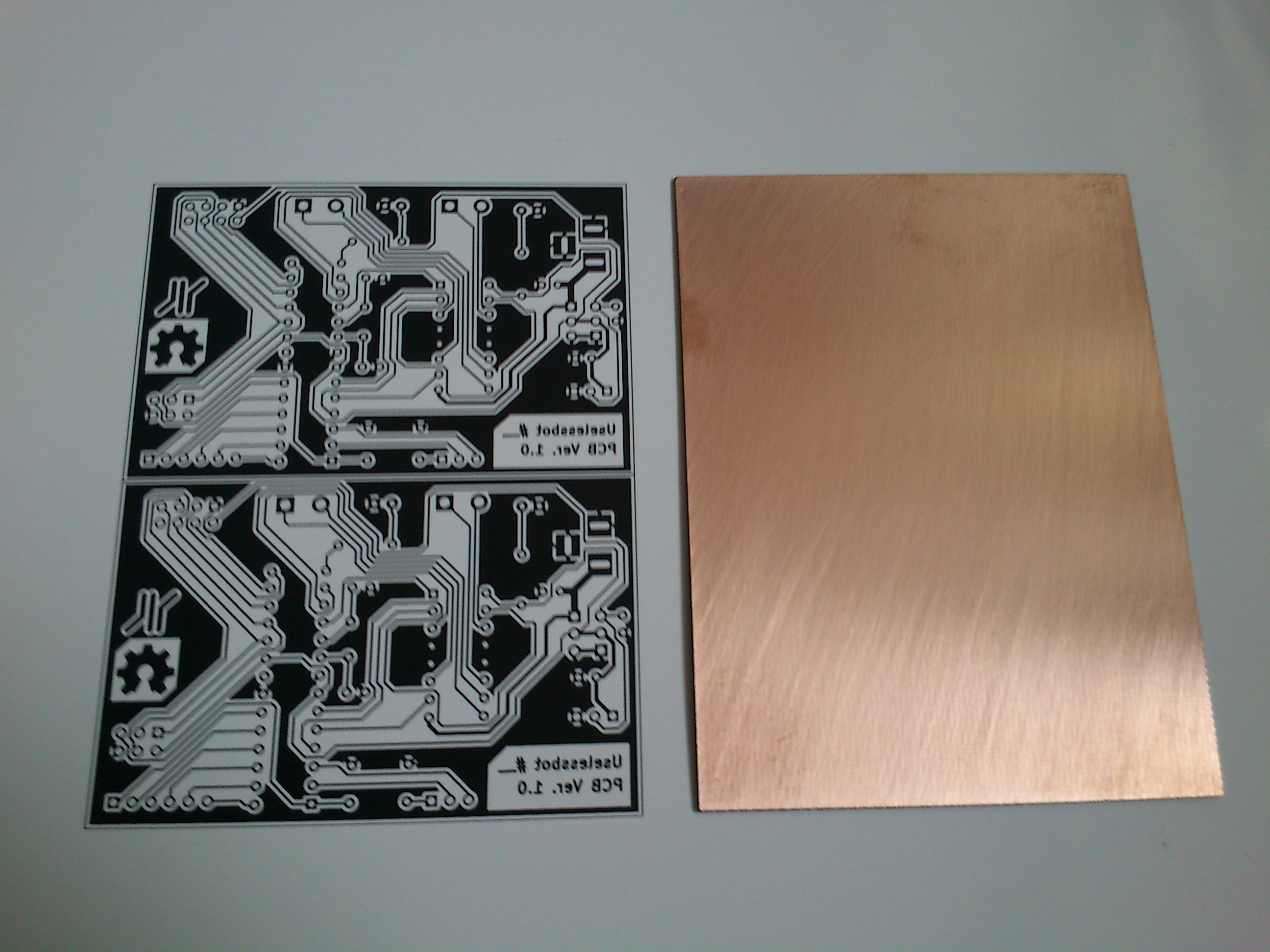
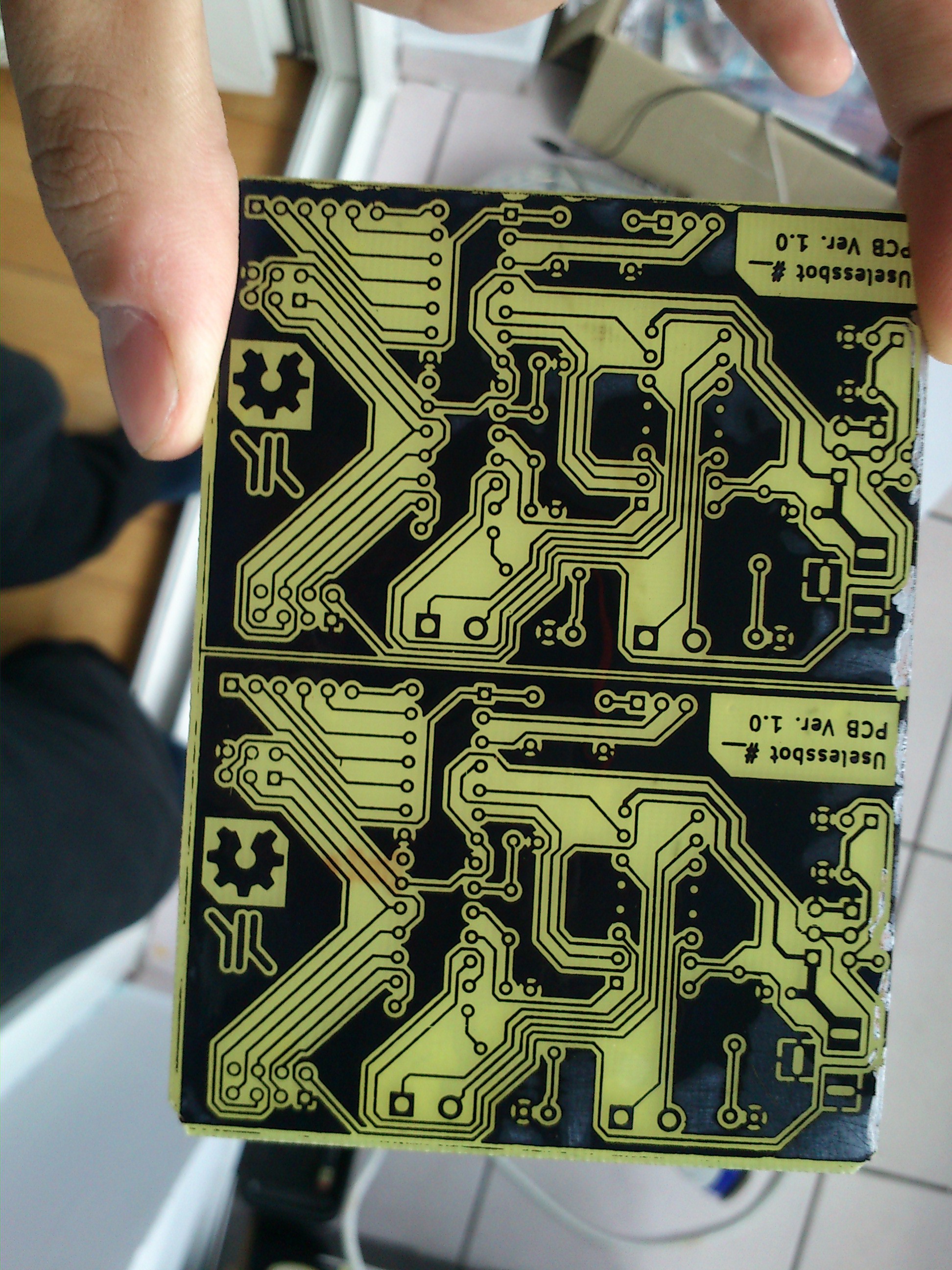
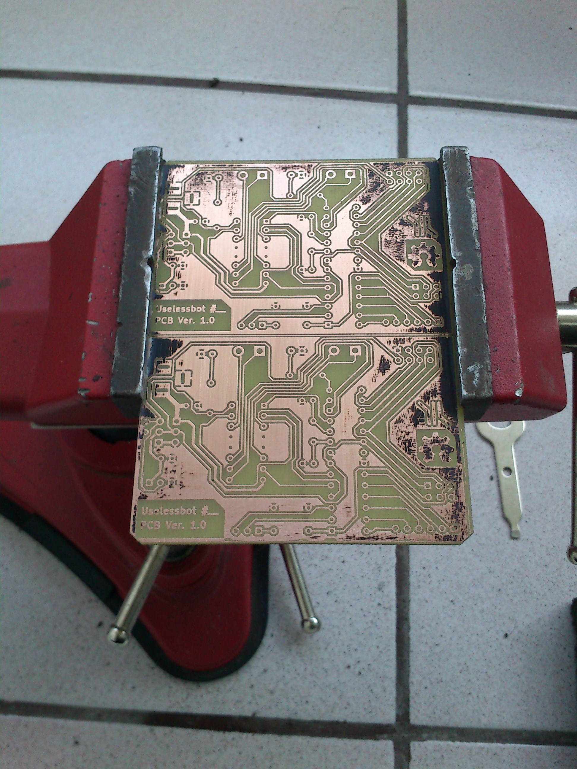
09/30/2014 at 06:50 • 0 commentsFor the first prototype, I manually etched the design on plain cooper-clad boards.
Home etching is something like old arcade games : Easy to pick up, but hard to master.
Since Ionly had plain copper boards, I chose the toner transfer method.
![]()
There are many guides on the net, but, unless you have the exact same materials, something is not going to work like you expect it to.
![]()
This usually ends in a few days of trial and error. After spending way more time than intended on wasting toner and a lot of paper, my magic combination came to :
- cheap, printer foto paper (waaaay better than glossy magazine paper.
-laser printer
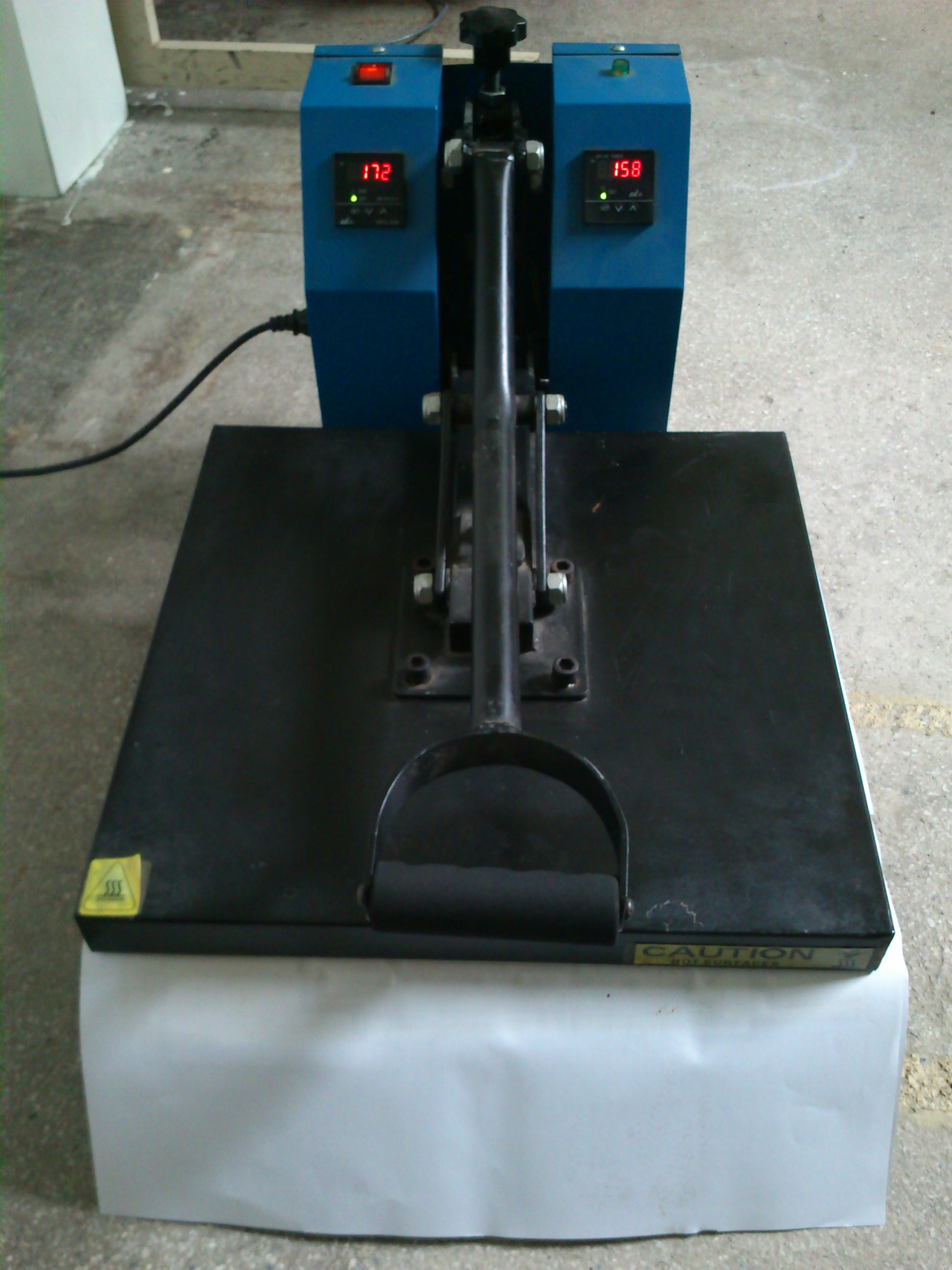
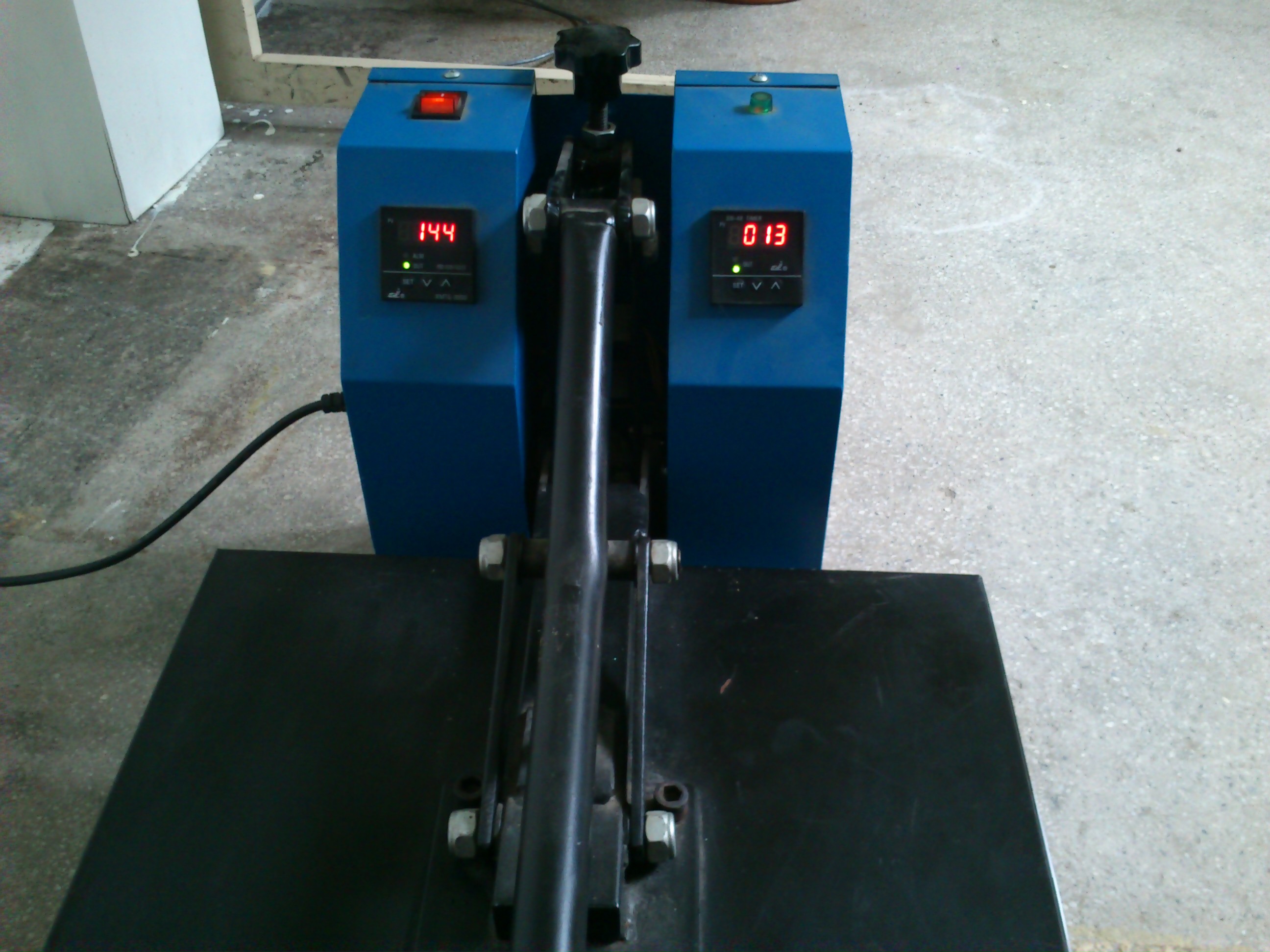
-secret ingedient: A heat press
![]()
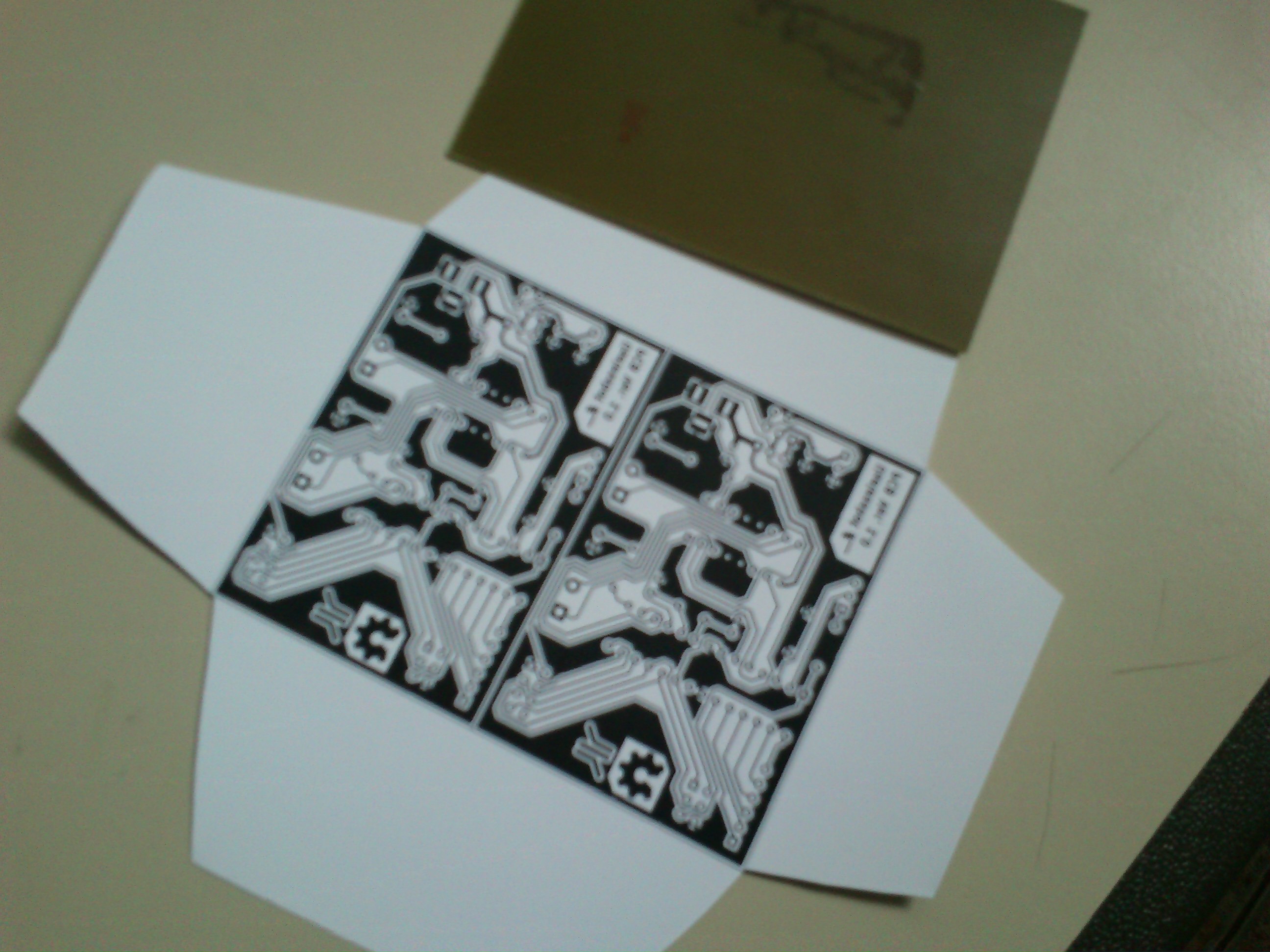
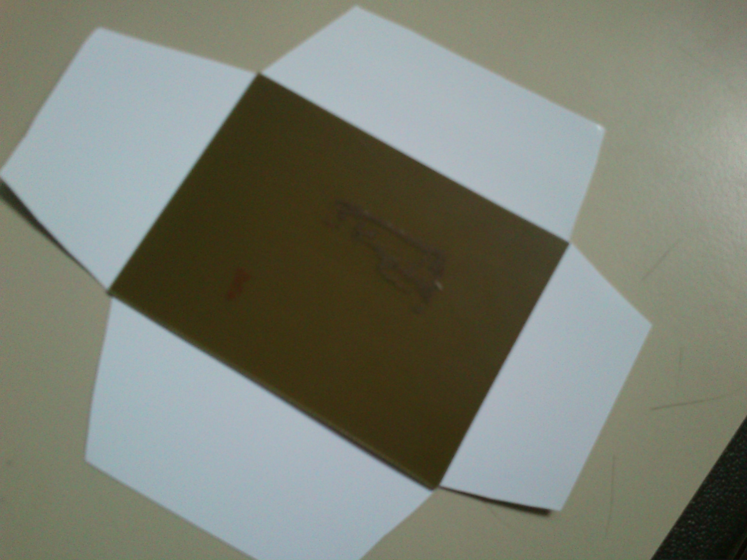
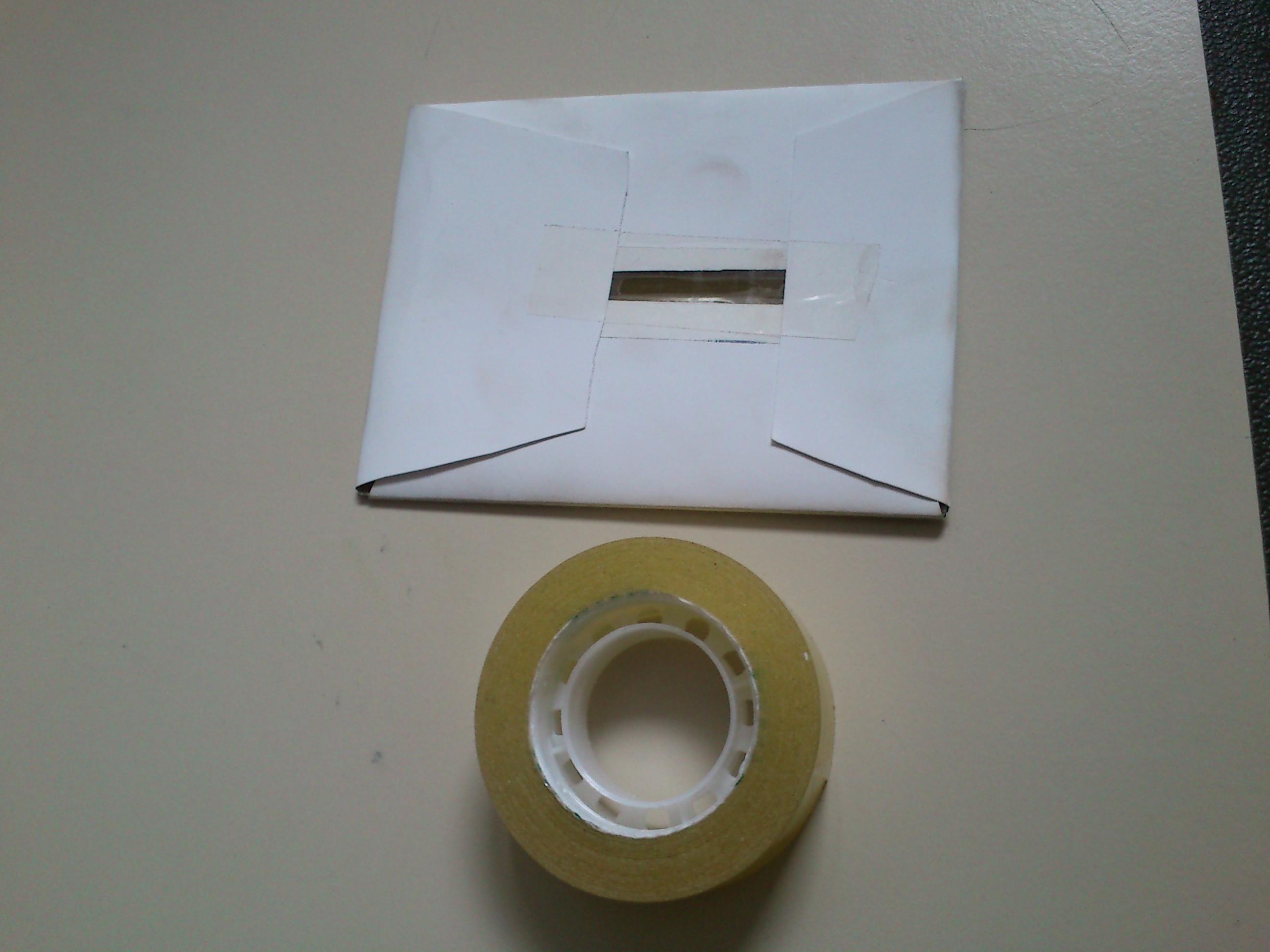
Usually, the toner is actually transfered to the copper when pressure and heat is applied to the paper. This is done with a household iron. However, this method is sloppy and results in poor quality.
![]()
![]()
![]()
![]()
![]()
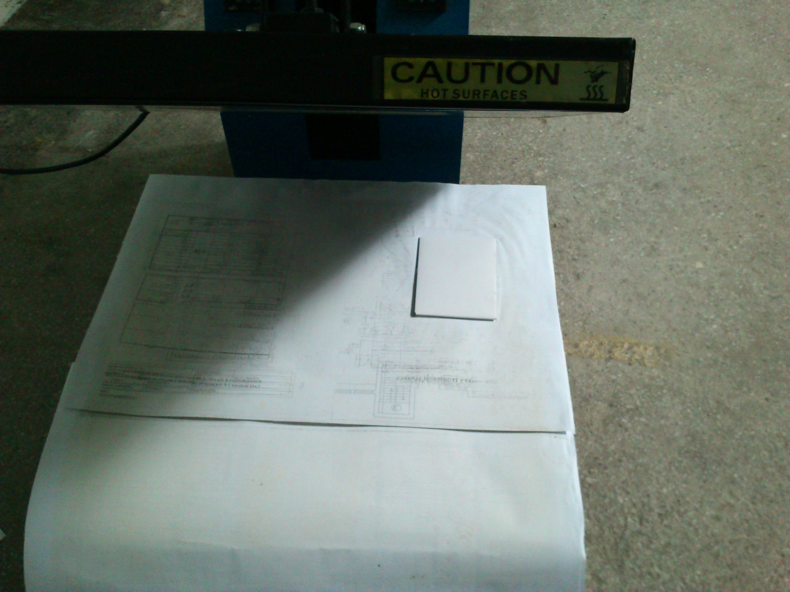
I solved this problem by chance. When I was checking out a shop that had a CNC, a heated press caught my eye. Since the CNC did not work, we borrowed the heat press and tried that instead of ironing the board. This yelded much better results because of the constant and even pressure. Usually 5 minutes in the press and the toner transfers 99%.
![]()
![]()
-
Teh brainzzz
08/20/2014 at 18:40 • 0 commentsThe ATMEL Atmega328 was chosen for the good price, wide availability and
wide community support. This chip is also used in the Arduino UNO
development platform that is usually the starter's platform when it comes to
embedded programming. Using the same chip should ensure a smooth
transition of newbies and experienced users alike.
The microcontroller features 21 GPIO pins divided in three ports :
Port B (PB7:0)
This port is reserved for the NRF24L01 communications module due to the
hardware SPI pins. An ICSP connector is also wired on the respective MISO,MOSI,SKC
and RESET pins
The clock circuitry is also on this port.
PB0 drives a onboard LED.
Port C (PB5:0)
This port is used as an analog input on the arduino board so we just used
an 6 pin connector to provide easy access for adding extra sensors and
inputs.
Port D (Pd7:0)
Port D drives the L293D Hbridge, and the enable pins on the L293D are
connected to PWM capable pins, (PD5 and PD6) to enable individual speed
control for each motor.
Also,the RX/TX pins (PD0 and PD1) are reserved for the user and extended
to an 3 pin connector that also contains the reset pin (PC6).
-
Swarm ready?
08/20/2014 at 18:37 • 0 commentsWhy yes, the cheap factor makes this design suitable for experimenting with swarm
robotics. It's easy to build with easy to find, off the shelf parts or easy to
massproduce. It could be sold in kits or preassembled. Due to the open
source and open hardware nature of this project, you or anyone else can
copy the design and build one at home or integrate it in a industrial design,
free of charge and without restrictions.
-
PCB design (prototype)
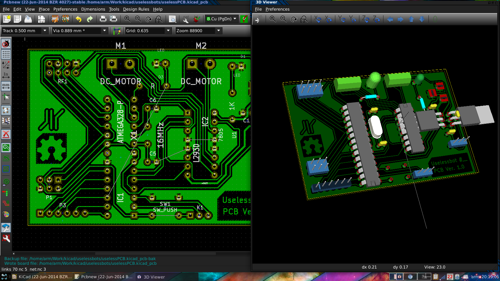
08/19/2014 at 21:00 • 0 commentsSince this was an early prototype, we first designed the PCB to be one layer and with through hole components. There will be at least 2 more versions:
-Dual layer THT (for kits)
-SMD version (for the pre-assembled variant)
We designed the PCB according to the datasheets of each component (Note the L293D does not have thermal relief pads on the ground pins, so the ground plane can act as a heatsink ) and according to standard design rules.
As for design/CAD software we basically had 2 options: KiCad an EAGLE.
We finally decided on KiCad, even if it's a bit harder to work with mainly because this one is open source and does not have any restrictions, like EAGLE (max number of layers / Use is limited to non-profit applications
![]()
(This was the only acceptable screenshot I could find of the design process. Besides, we still have to rule out some quirks before we release/licence the design)
-
Software:
08/19/2014 at 19:00 • 0 commentsThe robots will be programmed using Arduino. Using RF24/radiohead library to control the NRF24 communications module, the bots will be able to broadcast their state and intention and can receive missions from the swarm. The system will allow the swarm to organize and divide their power to accomplish multiple objectives in the same time.
The decisions in the swarm will be taken collectively, and each robot will have a certain state, and behavior based on his health and mission. This will translate into a availability to receive more missions.
On the low level programming, each individual robot will contain 3 layers:
-Basic control : movement, collision avoidance, receiving radio signal
-Orientation and mission: orientation to objective, accomplish mission
-Role in swarm and behavior: each robot state, availability and emotional state. (this will be adaptive)
The last layer will adapt the robot's role in swarm using a learning algorithm and receiving feedback from the swarm after every action. This changes will lead to efficiency in taking decisions.
The important order of layers is obvious, and the decisions will be taken, analyzing the most important layers first (ex. first avoid an obstacle if it is in the way to objective).
Uselessbots
A low-cost (~$10), self-contained, swarm-ready, Arduino-compatible, mesh-networked, open-source, open-hardware, useless ROBOT!!
 [ E C C 0 ]