-
Step 4: Building the master box.
08/16/2014 at 18:12 • 0 commentsA little more work went into building the master box, but not that much.
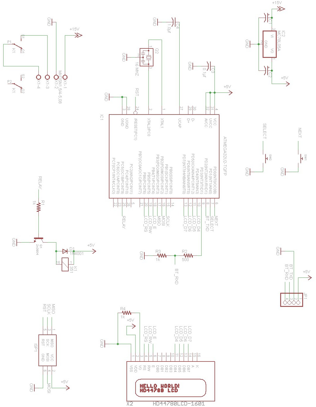
Here is the schematic to the master box :
![]()
This circuit is very simple. 7 lines control the LCD , in 4 bit mode. There are 4 data lines and 3 control lines. Pin 3 of the LCD is connected to a 1k resistor to ground to set the contrast. There are 2 switches to manipulate the master box. Switch 1 is used to enter the settings mode, where you can change the PIN to unlock the door. It is also used to switch between options inside settings. Switch 2 is used to select the displayed option. Both switches are pulled up internally so they only need to be closed to ground to change state. The Bluetooth module's TXD pin is connected directly to the MCU and the RXD goes through a resistor bridge to lower the voltage to 3.3v towards the Bluetooth module. Port C pin 5 drives the relay that simulates pressing the button on the intercom. RST, SCLK, MOSI , MISO are needed for the AVR ISP connection along with a connection to ground, and power to the AVR. A 5v voltage regulator drops the 15v coming from the intercom to 5v and is filtered with a 1µf at the input and output of the regulator.
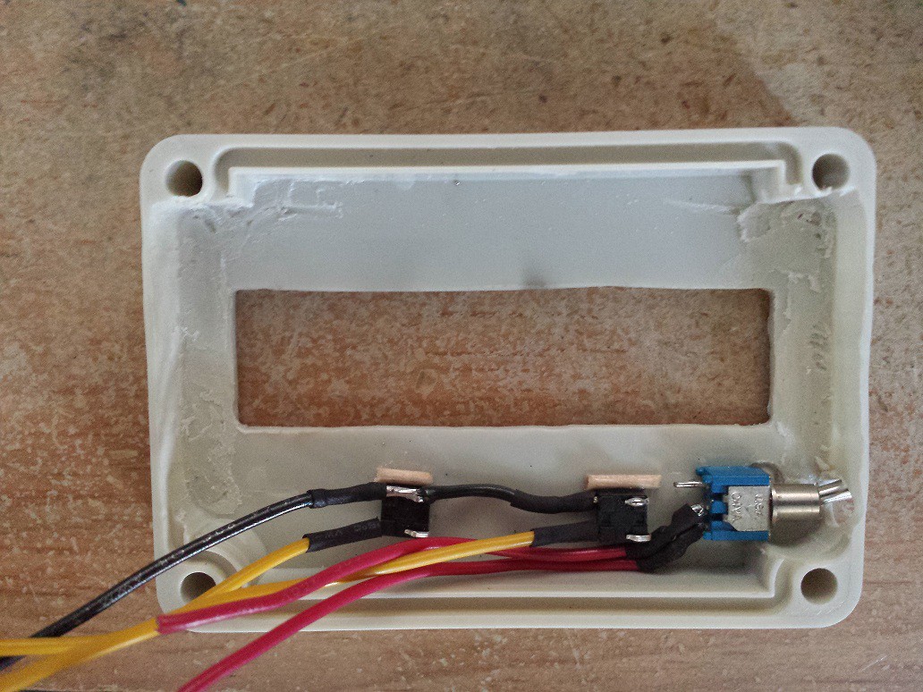
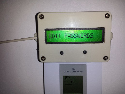
Fitting the LCD was tight, but it turned out perfect. Using my dremel I cut the plastic but sadly I went to close to the side, bottom right and I went through the plastic. So I decided that's where the power switch would go. I drill 2 holes for the switches and cut a piece of toothpick to help glue them more solidly with super glue.
![]()
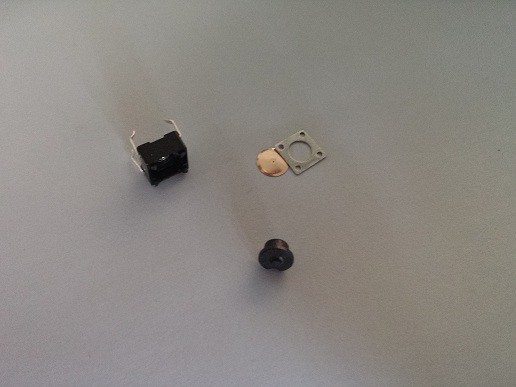
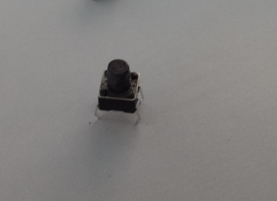
Both switches are grounded on one side , and connected to their respective pad on the board. The buttons for the switches were too short to come out the other side of the box. So I cheated and destroyed 2 extra switches and took the buttons, sanded the excess and glued them on top of the switches to make them taller :
![]()
![]()
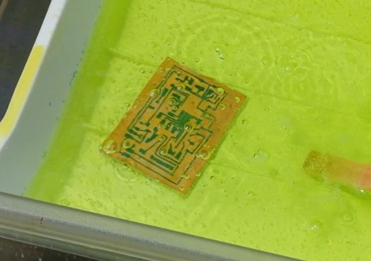
This board turned out much cleaner than the slave keypad board, but this was also a different board that wasn't as old as the one used for the keypad. Here is a shot during the etching process using muriatic acid :
![]()
You should do this outside! There are a lot of fumes and your girlfriend might not enjoy the smell it leaves in the washroom once you are done.
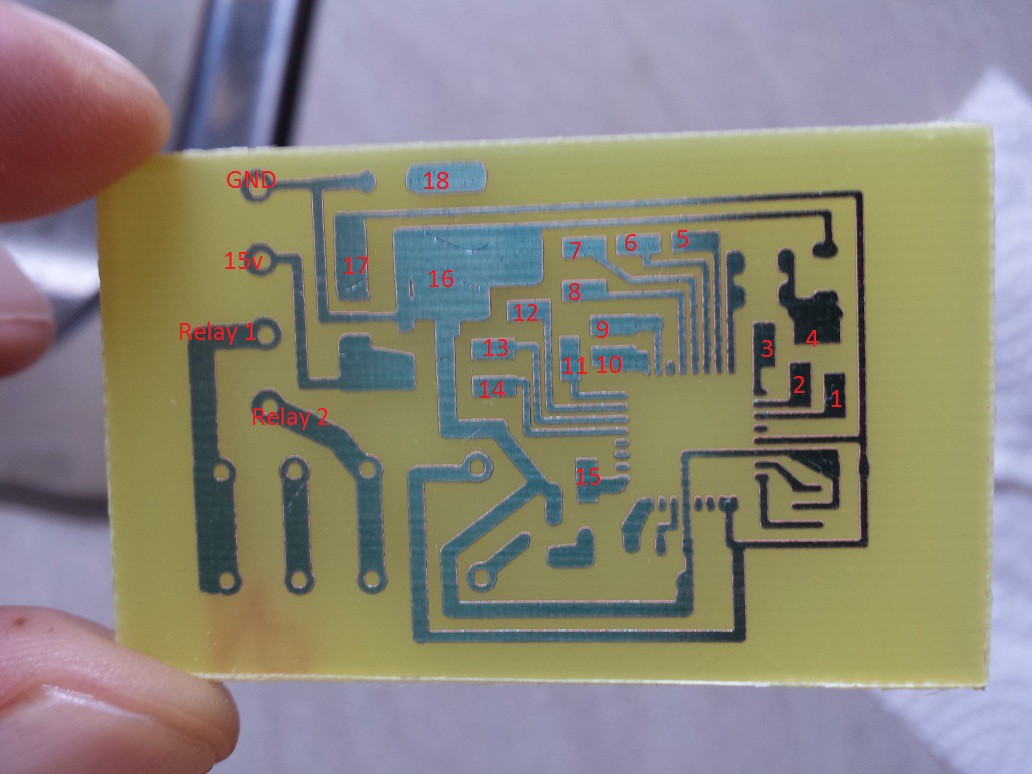
![]()
- Switch 1 is 1 and 16.
- Switch 2 is 2 and 16.
- Bluetooth is 5v: 17 GND : 16 RXD : 4 TXD : 3
- LCD is : E: 12 RW : 13 RS : 14 D4: 5 D5: 6 D6 : 7 D7 : 8 5v : 17 GND : 16 CONTRAST : 18
- AVR ISP : SCLK : 9 MOSI : 10 MISO : 11 RESET : 15 GND : 16 5v : 17
- GND is connected to the ground of the 15v regulator inside the intercom.
- 15v is also connected to the 15v regulator of the intercom.
- Relay 1 and 2 are connected directly to the switch that is pushed on the intercom when you want to unlock the door.
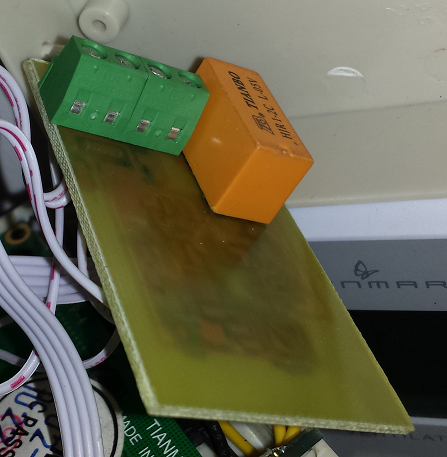
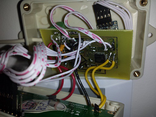
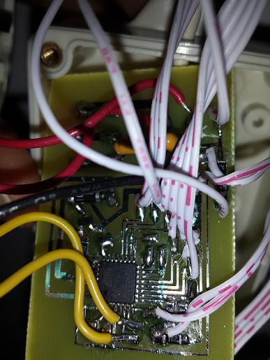
I forgot to take pictures just after populating the board, so here are some take once everything is wired :
![]()
![]()
![]()
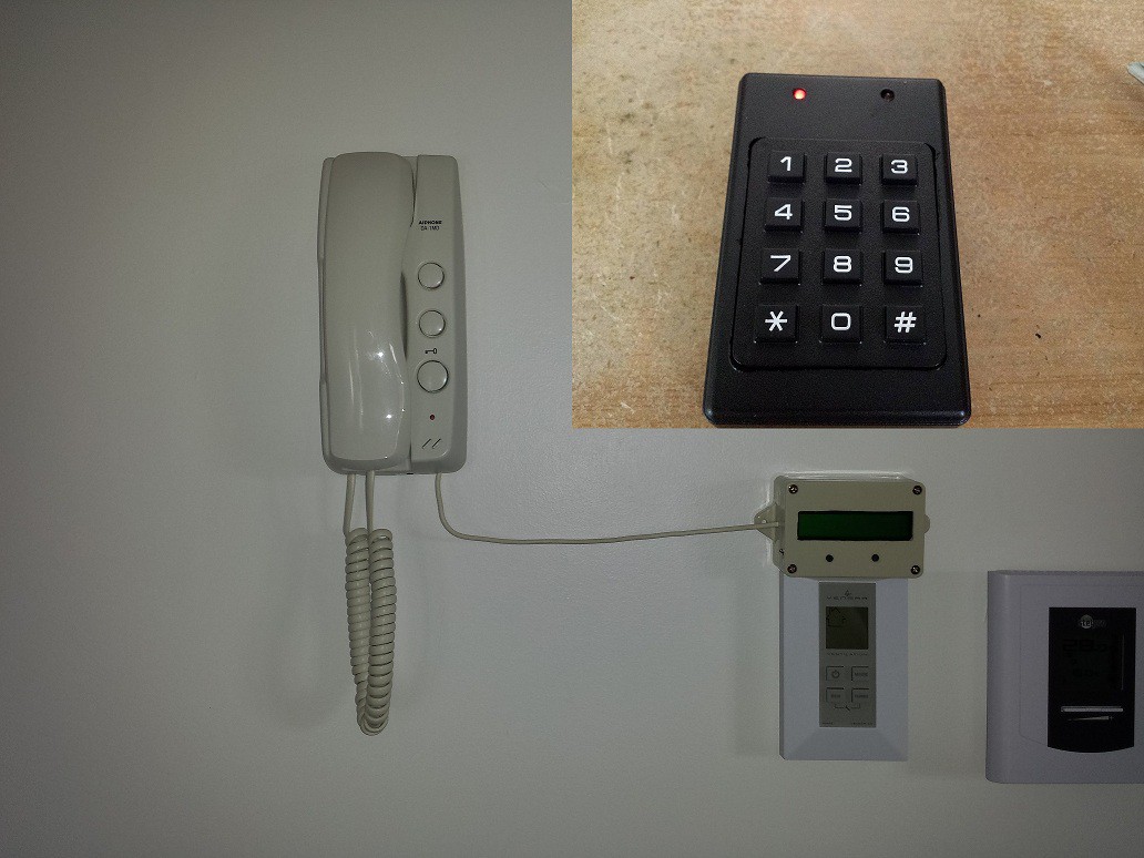
I used a 4 wire telephone cable connected to the phoenix connector inside the master box and soldered directly inside the phone :
![]()
![]()
-
Step 3: Bluetooth modules setup.
08/16/2014 at 18:06 • 0 commentsOnce the modifications to the boards are done, they now have to be setup properly. My code is divided in 3 parts under main(), selectable by a definition. Define either SETUP , SLAVE or MASTER in order to compile the board. The Bluetooth modules are setup using the keypad box , using the SETUP compilation.
You need to modify the code to fit your boards. The steps needed are :
- Change the "password command" to the Bluetooth password you want to use.
- Change the "bind command" to bind to the address of your current modules. This is different for each module.
- Compile the project with SETUP defined.
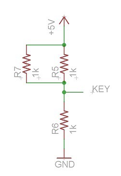
- Make a resistor bridge with 3 x 1k resistors.
- Flash the keypad box with the compiled SETUP hex file.
- Connect the KEY pin to your resistor bridge to provide 3.3v
- POWER ON the keypad box.
- Press the key matching the command you want to use.
![]()
I used my logic analyzer to view the module's response to my commands , but it is not absolutely necessary. Since the keypad box doesn't have a display, there is no output to tell you if the command was received properly. The HC-05 firmware has 2 LEDs to show its status, and they are on a different pin than the HC-06 firmware, so the breakout board is not wired properly. I did not modify the board to have the LED working because I do not need it in my project. I did use my logic probe to check the status of pin 31 to confirm the module was in AT mode. AT mode is required to setup the modules. While in this mode , the module will not output the data it receives , but instead it uses it to setup some parameters for its normal working mode.
There are 2 modules needed , the master module and the slave module. You cannot connect 2 slave modules together, hence the reason why the HC-06 firmware was not good for my project. In this project , the modules are bound to each other. No other devices can connect to them and send data. To bind the modules, you need the other module's address. There are a few ways you can acquire the addresses. The easiest is simply by powering your module and trying to connect to it to see its address. I used my android phone with blueterm+ and was able to quickly see the addresses. Using your PC to connect to it will also work. The default password is 1234 of course. If you have a logic analyzer you can use it to read the response of the module when you press key 7 on the keypad flashed with the SETUP program. The baud rate for the AT mode is always 38400 8N1. You can also get the addresses when you are flashing the HC-05 firmware,
One of my module address is : 2014 04 159158 but when you send the command AT+ADDR? The modules responds 2014 4 159158 , dropping the lead 0 of the 2nd part of the string.
You need to change the code for keys 2 and 3 to reflect the module's addresses with the address corresponding to your module. According to the datasheet the format is : AT+BIND=1234,56,abcdef\r\n
Here is the code for key 2, which is used to bind the slave module to the master module's address :
if (buffer == 2) // Bind to master
{
   tot_overflow = 0;
   USARTWriteChar('A');
   USARTWriteChar('T');
   USARTWriteChar('+');
   USARTWriteChar('B');
   USARTWriteChar('I');
   USARTWriteChar('N');
   USARTWriteChar('D');
   USARTWriteChar('=');
   USARTWriteChar('2');
   USARTWriteChar('0');
   USARTWriteChar('1');
   USARTWriteChar('4');
   USARTWriteChar(',');
   USARTWriteChar('0');
   USARTWriteChar('4');
   USARTWriteChar(',');
   USARTWriteChar('1');
   USARTWriteChar('5');
   USARTWriteChar('3');
   USARTWriteChar('9');
   USARTWriteChar('2');
   USARTWriteChar('9');
   USARTWriteChar(13);
   USARTWriteChar(10);

}- Key 2 is used to program the slave module to be bound to the master module, so it contains the master module's address.
- Key 3 is used to program the master module to be bound to the slave module, so it contains the slave module's address.
- Key 6 is used to program the 4 digit Bluetooth password to both slave and master modules. They must both match for a connection to be successful.
You can now compile the SETUP program, flash it to the keypad box and be ready to setup both of your modules. Connect the module you want to use as master to the keypad box. Connect the KEY pin to 3.3v and power on the module. Now press (wait a second between each presses) :
- 8 to set the working baud rate of the module in normal working mode to 38400 8N1 (that's the baud rate used in AT mode, and in my project).
- 1 to set the module to auto connect mode (default mode).
- 3 to bind the master module to the slave module's address.
- 4 to set this board to master.
- 6 to set the password. (default is 1234).
The master module is ready! Now power off and disconnect it. Now connect the module that is to be used as slave, power on and press :
- 8 to set the working baud rate of the module in normal working mode to 38400 8N1 (that's the baud rate used in AT mode, and in my project).
- 1 to set the module to auto connect mode (default mode).
- 2 to bind the slave module to the master module's address.
- 5 to set the board to slave (default).
- 6 to set the password. (default is 1234).
The slave module is ready! From now on , when both modules have power , and have established a connection (takes a few seconds) whatever appears on the RX line of one module will then appear on the TX line of the other module! It couldn't be easier to send data wirelessly!
-
Step 2: Building the keypad box.
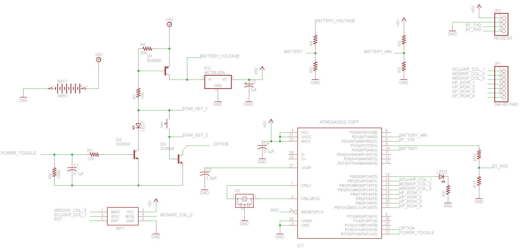
08/16/2014 at 13:30 • 0 commentsBuilding the keypad box is very simple. The schematic was designed with eagle and the board was drawn using a french software called "Tracé de CI" which translates to "Printed Circuit Router". The schematics are posted in the project's pictures, but for some reason the site rotated them. I will explain the keypad schematic :
When closing SW1 transistor Q1 closes and connects the 9v battery to the AVR. The first thing the AVR does is it sets PC7 (power toggle) high. Now when PC7 is high , Q2 will close , lighting up the LED and keeps Q1 closed as you release SW1. Q3 is connected to the AVR to PC6 as an option pin, but is not used. This circuit design was taken from the AVR Transistor Tester and is a very good way to save the battery. The BATTERY and BATTERY_MIN use a simple resistor bridge connected to the comparator of the AVR and will detect if the battery is low voltage, flashing the LED before it lets you enter the PIN. The keypad is connected to port B at pins 1 to 7 with the 3 column pins shared with the AVR ISP to program the board. Port B pin 0 is the OUTPUTLED that will flash when keypad is powered on with a low battery, will then remain solid until a connection is confirmed with the master box and then turn off. It will also light when you press a button and when it sends the data to the master box. The RXD pin , PORT D pin 2 is connected directly to the Bluetooth module , while the TXD pin, PORT D pin 3 is going through a resistor bridge to lower the voltage to 3.3v.
![]()
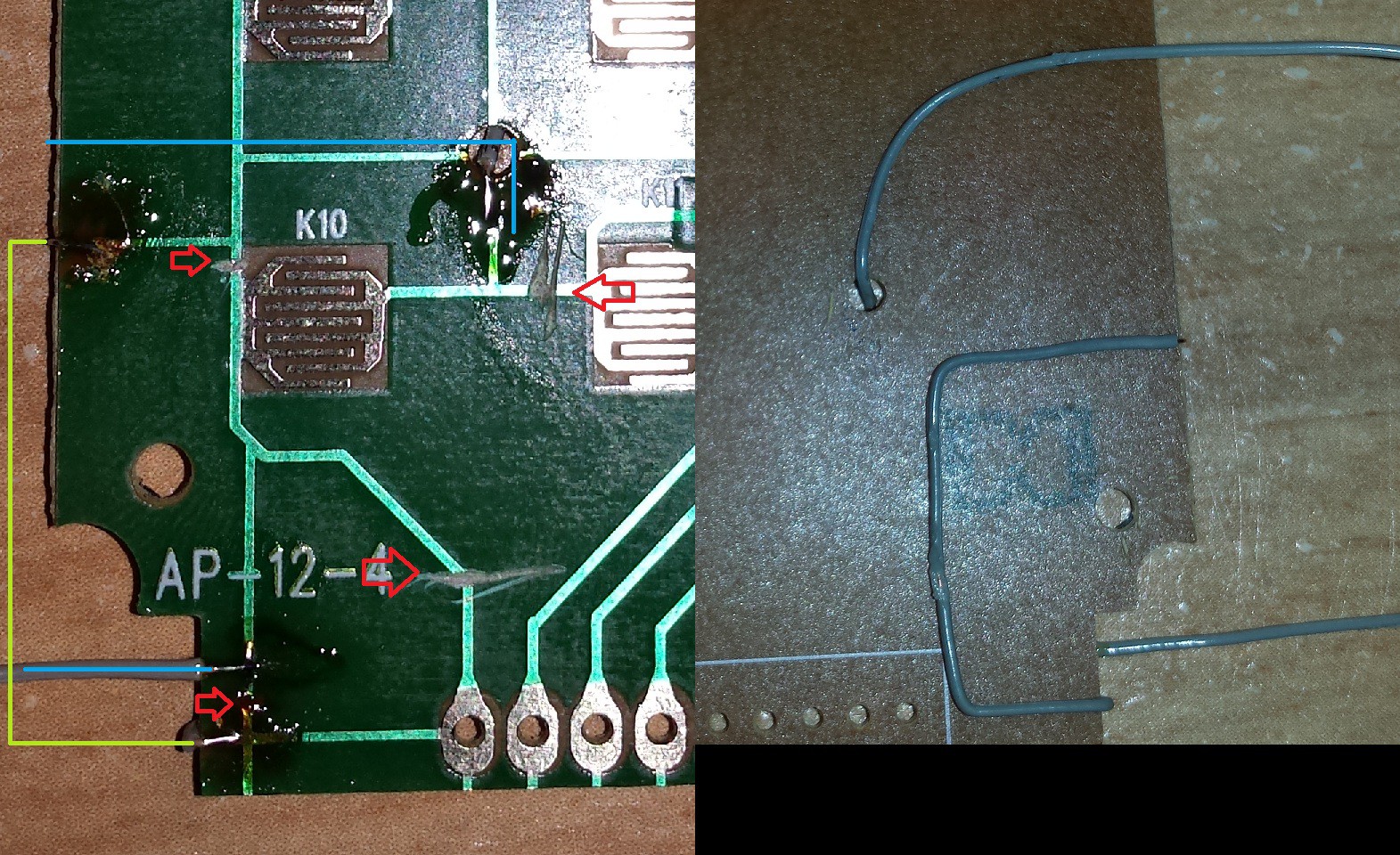
I modified the keypad itself so I could isolate the * (star) key and use it as SW1 instead of having it wired to the 4x3 matrix.
![]()
The red arrows point to the cut traces. The greenish line shows the column being reconnected after skipping the star key, and the blue lines are the connections to the switch connected to STAR_KEY_1 and STAR_KEY_2 on the schematic. This leaves all 11 other keys working and the star isolated from the rest.
![]()
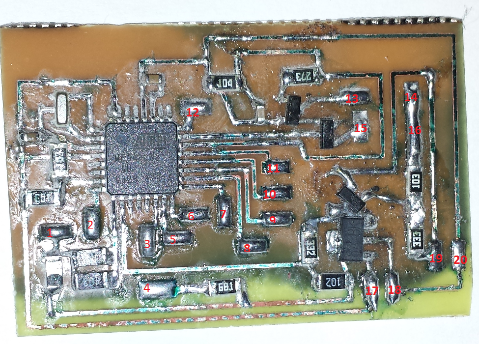
This is definitely not the best looking board I ever made , as you can see this is a double sided board that hasn't etched completely on the other side , but since I'm using just one side , and that the resistant coating was starting to peel off I pulled out the board before it was over etched. I used muriatic acid and peroxide to etch this board, as this instructable shows. This board was at least 7 years old , and I suspect the coating to be somewhat out of date. I got much better result using a more recent board for the master box. I wanted to keep the board as small as possible and avoid jumpers so instead I placed pads all over where the wires are needed for the keypad , Bluetooth, LEDs and 9v connector. Also not shown here is a 1µf tantalum capacitor connected to the 5v line. Once populated I used the pads to connect the ISP connection and flash the module. The keypad, star key and the POWER LED need to be connected otherwise the board will not power on. To flash the module you will need to hold down the star key during the entire flashing process because the MCU cannot keep the transistor closed while it is being programmed. You could also just connect a wire instead of a switch. I recommend using the female pin connector cable that came with the Bluetooth module so you can easily unplug and switch modules, because the keypad box is used to prepare both the master and slave Bluetooth modules, so you will need to swap them.
Here is the "pinout" of my board :
- SW1 is 15 and 16
- POWER LED is 13 and 14 , with 13 being the cathode.
- Bluetooth is : 5V: 17 GND : 18 RXD: 1 TXD : 2
- OUTPUT LED is 3 and 4 , with 4 being the cathode.
- ISP : CLK : 5 MOSI : 6 MISO : 7 RESET : 12 GND : 18
- KEYPAD : COL_1 : 5 COL_2 : 6 COL_3 : 7 ROW_1 : 8 ROW_2 : 9 ROW_3 : 10 ROW_4 : 11
- 9V Connector : 9v: 19 GND : 20
Once everything is connected it is time to flash the AVR with the SETUP compiled code and setup the Bluetooth modules.
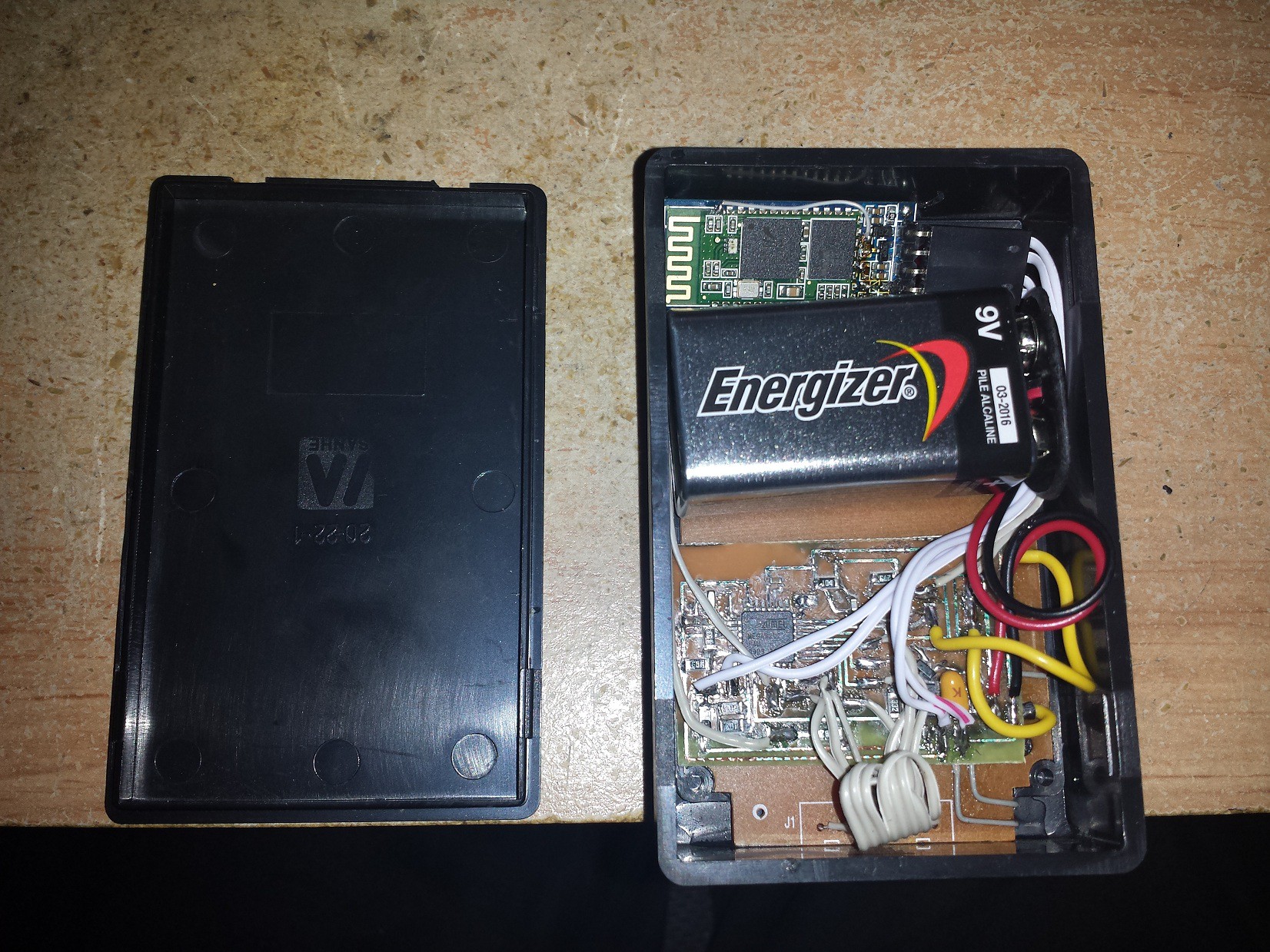
Here is everything crammed in its box, without the AVR ISP connection:
![]()
The keypad is super glued to the case and the board is glued to the keypad. The Bluetooth module and battery are left floating but with the back cover closing tight with the battery, nothing moves.
![]()
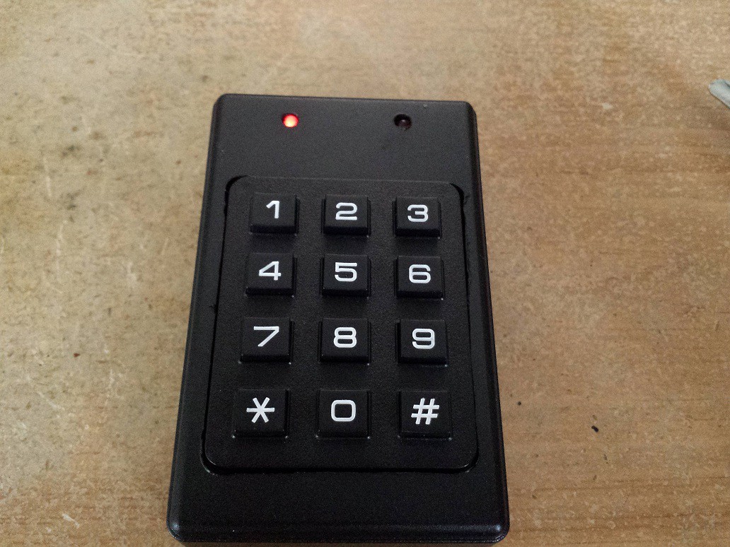
The keypad boxed powered up, and synced (right LED turned off). Press the star key, both LEDs will turn on. Wait for right LED to turn off. Once off, enter your 4 digit PIN and the door unlocks.
-
Step 1 : Preparing the Bluetooth modules.
08/16/2014 at 13:28 • 0 commentsThe Bluetooth modules I used are the very common CSR Serial to Bluetooth modules. I bought them from dealextreme. Sadly I realized while waiting for my order to arrive that they were HC-06 modules (slave only) and not HC-05 (Selectable between slave and master) So browsing the web to find out more about the modules, I found all the info I needed right here: HC-05 / HC-06 After finding an old windows xp computer that had a parallel port, I managed to flash the HC-05 firmware provided by Byron. I will not cover the steps to change your firmware to HC-06, because all info can be found on Byron's blog.
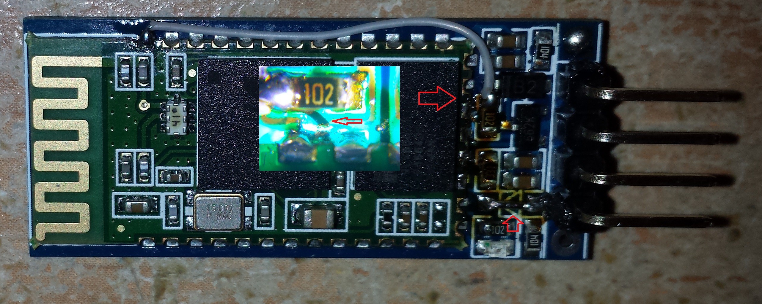
Now the board on which the modules came are layed out for the HC-06 pinout which differs a bit from the HC-05 pinout (all this info on Byron's site). So once flashed, the LED no longer works and the KEY pin required to place the module in AT mode is not wired to the correct pin. A little modification is needed to get the KEY pin working. You need to get the module in AT mode , and send a few commands to prepare the module the way you want to, ex. setting password, module name, baud rate, etc. Unless you plan to have the module change between master and slave on the fly, or change other more important settings, you will only need to get into AT mode once. Also the module's TX pin has a diode in series, bringing the line's voltage to only 2.6v and that wasn't enough to trigger the AVR which is running 5v. This diode was remove and replaced with a wire to get the 3.3v volt output, which is enough to drive the AVR. These boards can accept 5v as VCC , but it is not recommended to drive the RX line directly at 5v. A simple resistor bridge is used to keep the RX pin at 3.3v .
![]()
The new KEY pin is now pin # 34 where the gray wire is soldered. I cut the trace after the resistor and wired it to the key pin on the module, this way I could use the KEY from the breakout board. Also notice the diode at the bottom was removed and replaced with a wire. I'm sure a wire directly from pin 34 would of worked just as well, but this gives a more permanent solution. The microscope shot I pasted on top of the module is the cut trace from the 1k resistor.
Once the modifications to the boards are done, they now have to be setup properly. My code is divided in 3 parts under main(), selectable by a definition. Define either SETUP , SLAVE or MASTER in order to compile the board. The Bluetooth modules are setup using the keypad box , using the SETUP compilation.
Bluetooth Doorlock
A wireless door lock key pad and receiver using AVR and HC-05 Bluetooth modules.
