DSP 01: hi-fi audio signal processor
a digital signal processor with integrated multi-channel amplifier for high-fidelity speakers.
a digital signal processor with integrated multi-channel amplifier for high-fidelity speakers.
To make the experience fit your profile, pick a username and tell us what interests you.
We found and based on your interests.
in the previous update, i fretted about the 146Hz node in my listening room, and wondered if i could fix it. you can't just fix it by turning up the gain at 146Hz - it's like pouring sand into a black hole. the problem has to be fixed acoustically, so it's time to try bass-trapping.
bass-trapping is the process of shoving huge amounts of foam and/or fiberglass into the edges and corners of a room to dampen a room's low-frequency modes. it's a popular thing to do in listening rooms and/or home studios, and some people think it's the very first thing you should do. i'm not convinced. that much damping material is really going to cost you, and mounting it in a habitable space is quite non-trivial. but i like science, which means i have to try. i have to try to do it right.
so here's the experiment - get one block of acoustic foam at a decent price, mount it in the most theoretically sound place (ha), and see if the change is worthwhile enough to justify further expense. here we go!
i want to damp the 146Hz mode specifically. i have one big foam block, and it has to count. where should i mount it?
here's where some science comes in. sound travels through orthogonal fluctuations in pressure and velocity. my foam block should have the maximum effect if i place it in a high-velocity region of the 146Hz mode. somewhere in the room, the 146Hz mode has a velocity antinode. how can i find this antinode?
well, my speakers are pressure sources. my microphones are pressure sensors. and velocity is orthogonal to pressure.
so if i play a 146Hz tone through my speakers, and i can find a spot somewhere in the room where the sound pressure is abnormally low, that should be a high-velocity spot - the best spot to place my block of foam.
here's a needlessly complicated way to probe the room for sound pressure:
that's a Nexus 5 running AudioTool, connected to a calibrated Dayton iMM-6 measurement microphone. i probe the room with the phone mounted at the end of a long stick. it streams video (screen mirroring) through a Chromecast so that i can wirelessly watch the spectrum. and all of this works, but you know what.. forget it.
this is what i actually used:
[a $20 SPL meter and a long stick.]
the speakers are now blasting 146Hz. some rummaging reveals a spot in the room where sound pressure is >15dB lower than almost everywhere else. it's a winner!
up there is our low-pressure spot, which should also be our high-velocity spot. it's about 2 feet away from each wall, which is not very surprising. i mean, the wavelength of sound at 146Hz is 7.6 feet. it's like this:
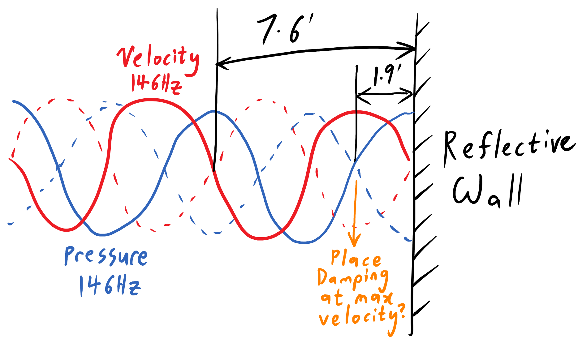
if 146Hz is reflecting off each wall, physics dictates that the lowest-pressure region is 1.9 feet from the wall. so far, everything makes sense. how can i put a foam block up there?
yes. all things are possible through my prodigious tripod collection.
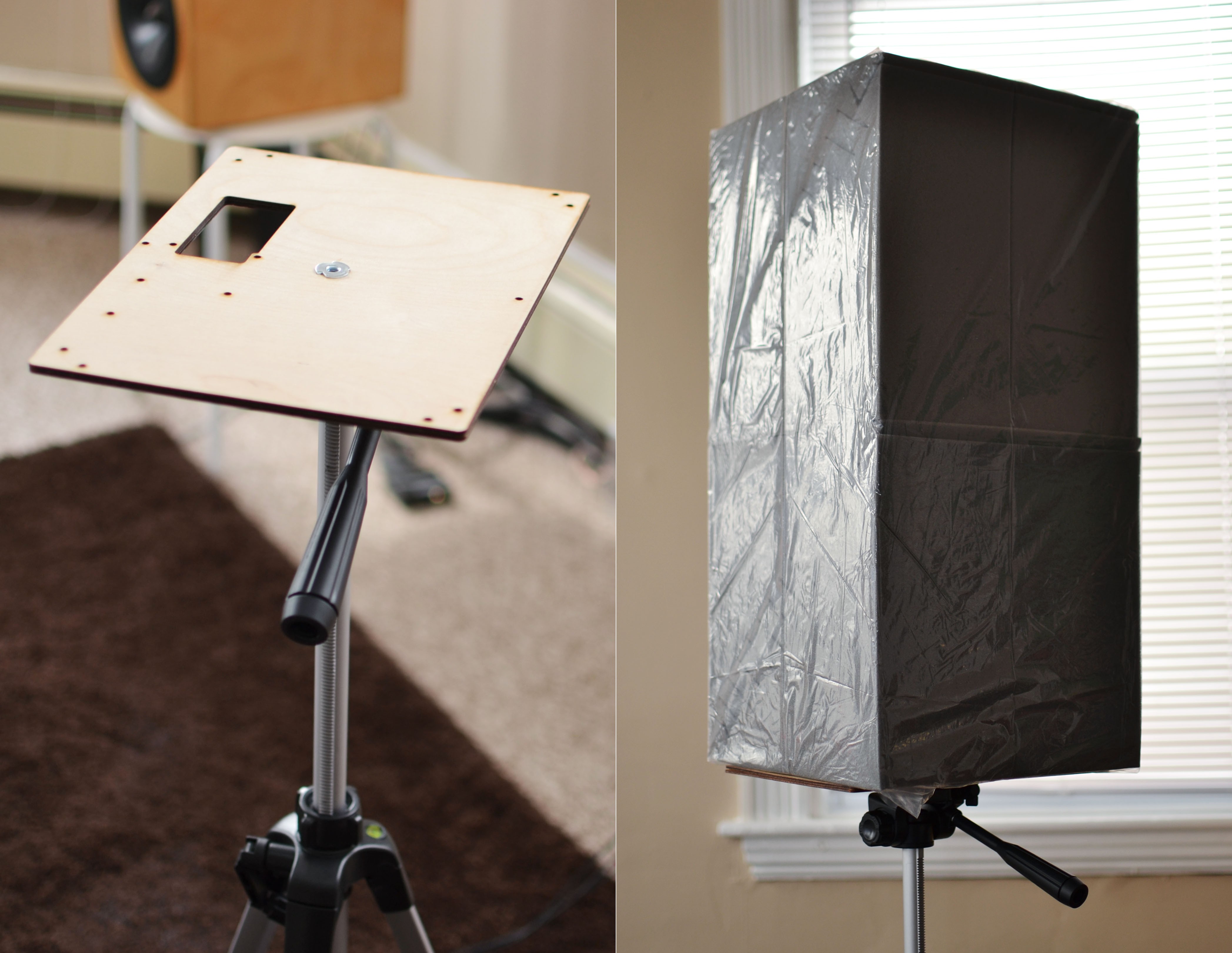
[it almost looks cool!]
my first step is to place the SPL meter at each of my four listening positions, and record the loudness of the 146Hz tone with and without the foam block.
here are the results (before and after):
that's.. not good? the difference is so small that it might as well be noise. so let's break out the real microphones, and compared averaged room measurements.
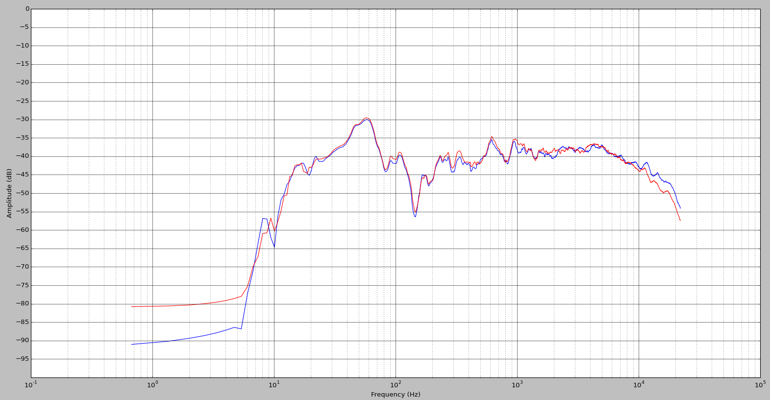
[left speaker frequency response, averaged over 4 listening positions, with 1/6-octave smoothing. without (blue) and with (red) foam block.]
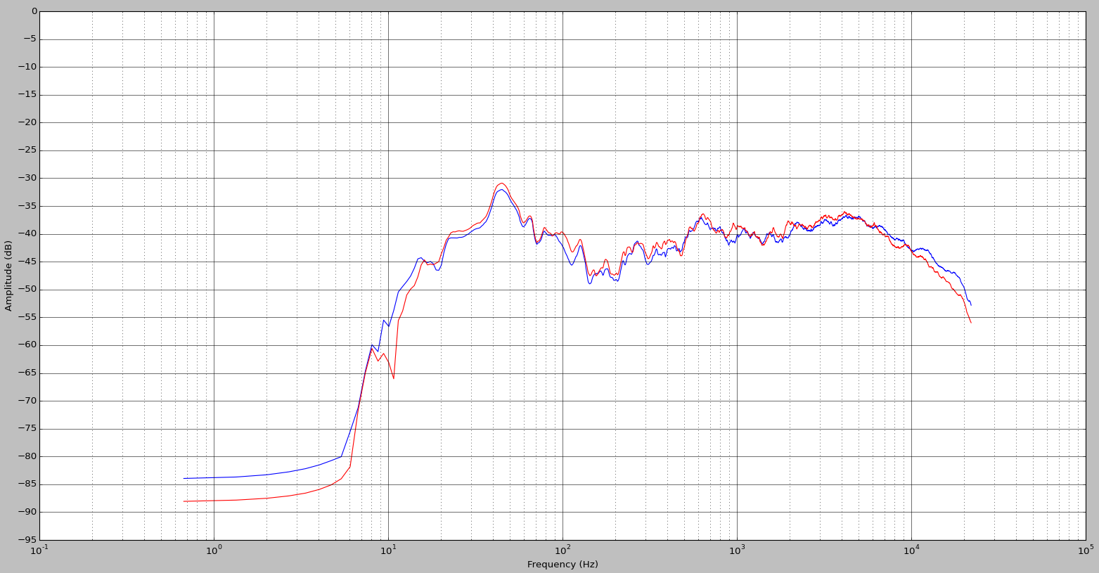
aside from slightly less treble (i left the 8.7kHz filter on) they're essentially the same curve. the...
Read more »i think i've hit the point where electronics and speaker design can only do so much. it's time to talk about acoustic room treatment.
two weeks ago, i was having sidewall-reflection problems. this means i was hearing too much reflected sound that had bounced off of the sidewalls of my listening room. this sound was interfering with the direct sound which traveled directly from the speakers to me.
of course, you're always hearing reflected sound. in fact, almost all the sound you hear in a typical living room is reverberated sound, which travels from the speakers to you after multiple reflections. without those reflections, you'd only hear a tiny part of your speaker's output, and you'd need enormous speakers to hear much at all. this is why outdoor speakers are enormous.
there is, however, one kind of reflected sound which i do need to control, and that is the first-reflection off of the sidewalls. it looks like this:

[direct sound (travelling directly to ear) and first-reflection (travelling from wall to ear).]
unlike the multiply-reflected reverberated sound, the first-reflection is much louder, arrives at the ear with a much shorter time delay, and is highly correlated with the direct sound. i find it quite audible and not very fun. so how can you control the first-reflections?

most people's first instinct is to cover their sidewalls with a thin layer of absorptive material. after some research they may also use 'fancy materials', such as 703 fiberglass. but a thin layer will only absorb the highest frequencies! if you are using mostly-omnidirectional speakers (as most of us are), that reflected sound is a big part of what you hear, and you're essentially cutting the highs out of the mix. what if you use thicker materials, to attenuate a wider range of frequencies?

here we've spent our money on much thicker layers of absorptive material, and can absorb both the mids and highs. sometimes this is a good solution, but i agree with certain experts that it generally is not, unless your room is tiny and desperately needs more absorption to reduce the reverberation time. this approach could leave you with a very dead-sounding listening space, and a huge disparity between the loudness of reverberated bass versus mids & highs!
one might ask - why not keep adding thicker and thicker layers of absorption until you can absorb the bass as well? you can indeed do that with bass traps, which are huge pieces of foam which can be mounted in the corners of rooms. the problem is, by then you've spent all your money, and you end up with a super-dead room which now requires enormous speakers, just like the great outdoors.
so instead of mounting absorbers on the sidewalls, i use diffusers instead. these are geometrically-complex surfaces which reflect sound in many directions. it looks like this:

[sidewall with acoustic diffuser - scattering the reflected mids and highs. nothing stops the bass!]
this also reduces the amount of sound which is reflected right at you. however, the rest of the sound is dispersed around the room, which adds to reverberation and doesn't upset the room's spectral balance.
so how does one construct these diffusers? if your blood is rich, you could buy and install professional diffusion panels. or you could construct your own (admittedly beautiful) Skyline diffusers. but even Floyd Toole just uses bookcases in his own house, and so shall i.
[right speaker is next to a bookcase with actual books.]
[if you own more e-books than books, you may have to use boxes and wooden panels instead.]
have you wondered why cinemas have padded seats? it's because people are squishy, and if the seats were less squishy than people, an empty cinema would sound substantially different than a full cinema. i take cues from cinema design, with an exceptionally squishy listening couch....
Read more »i built the DSP 01 as a platform for my audio projects. so now let's use it for something.
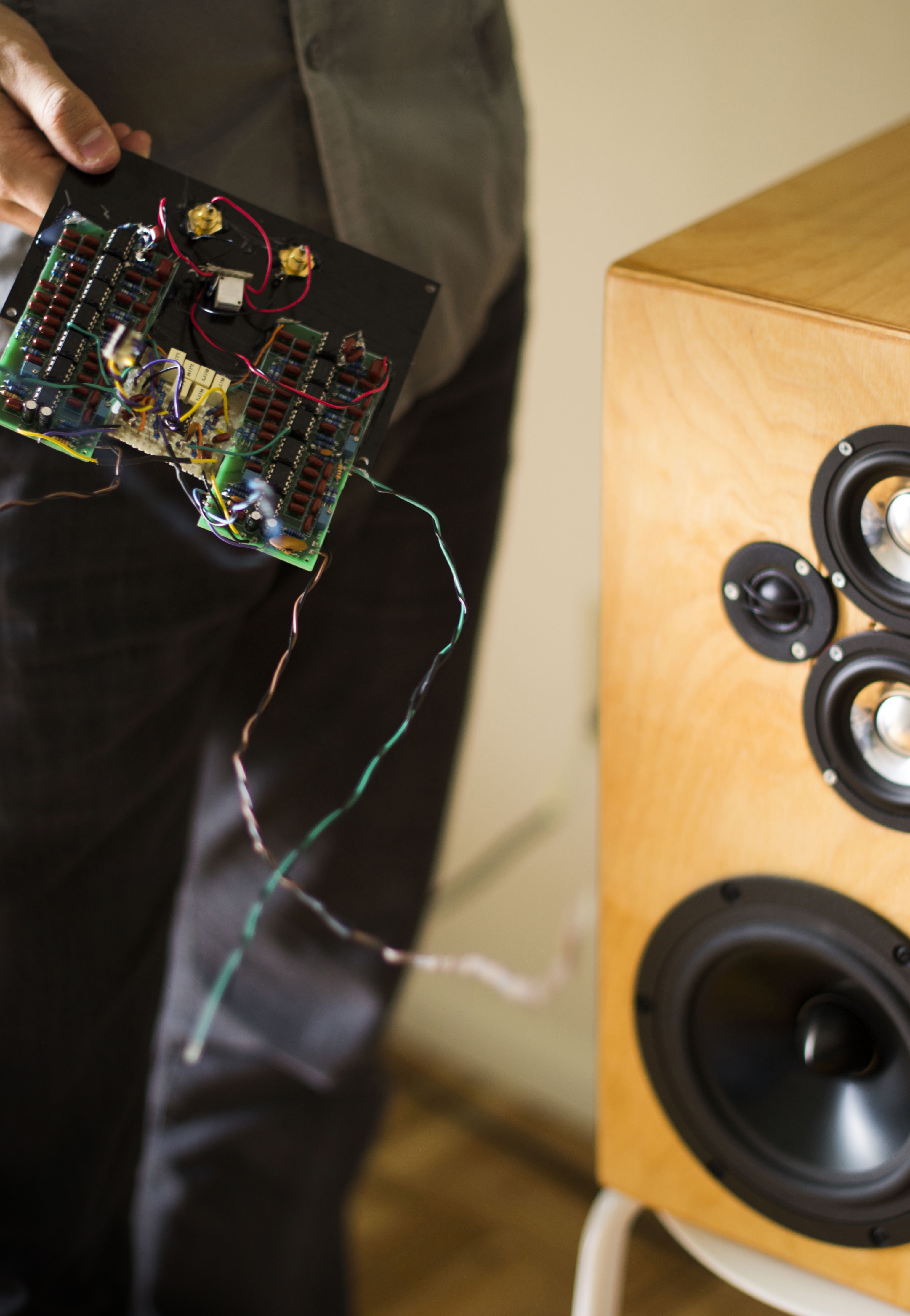
here's a speaker which i designed & built almost four years ago. i didn't know what i was doing back then, but the pair came out alright regardless.
it's a 3-way closed-box design, built to minimize distance between tweeter and (dual) midrange drivers. with a midrange-tweeter crossover at 2kHz, the off-axis performance is quite nice. the woofer crosses over at 300Hz, with a maximally flat (Q=0.71) roll-off below 57Hz.
on the left is the terrible analog signal processor which i built for them. it can go away now.
[goodbye!]
it's like getting a Bentley to replace a rusty bike.

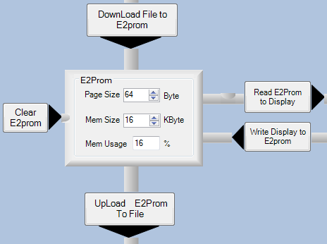
the newest version of DSP 01 uses a 16kB EEPROM with a 64-Byte page size. the EEPROM settings are tweaked accordingly:
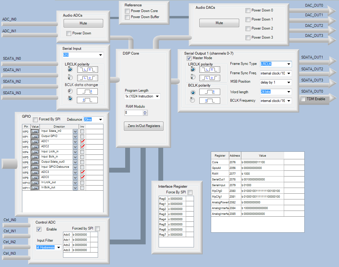
my new chassis has four knobs, so i have pins MP2, MP3, MP8 & MP9 all connected to the auxiliary 8-bit ADC. MP1 is an 'output GPIO' to control the clip-detect LED. MP0, MP4 & MP5 are configured to receive I2S audio from the CS8422. the other settings are about the same as last time:
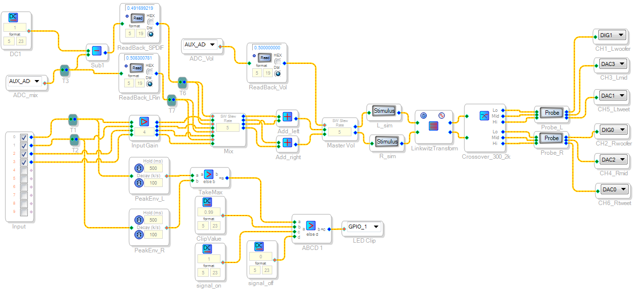
there's now four 'ticks' on the Input block because we have four input channels. Inputs 0 & 1 are our analog inputs, whereas inputs 2 & 3 are our SPDIF inputs.
i'm still using the same clip-detection method as before.
the Mix block allows the mix control knob to adjust the relative mix of analog & digital inputs .
there's only two frequency filter blocks here - they are Crossover_300_2k and LinkwitzTransform.
Crossover_300_2k is (unsurprisingly) the crossover between the tweeter, midrange and woofer drivers. it looks like this:
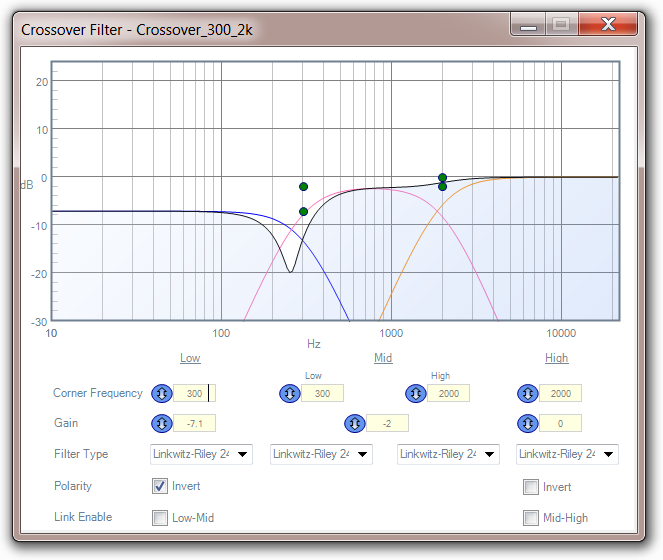
[woofers are attenuated by 7.1dB to compensate for the higher output voltage of the AK4430 DAC. polarity is inverted because the woofers are wired backwards internally.]
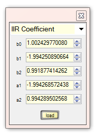
LinkwitzTransform implements a Linkwitz Transform on the woofer. it is essentially a biquad filter which cancels out the 57Hz roll-off of the woofers, and moves it down to 35Hz. as Sigmastudio doesn't have a 'Linkwitz Transform' filter block, i implemented it as a custom IIR filter. it looks like this:
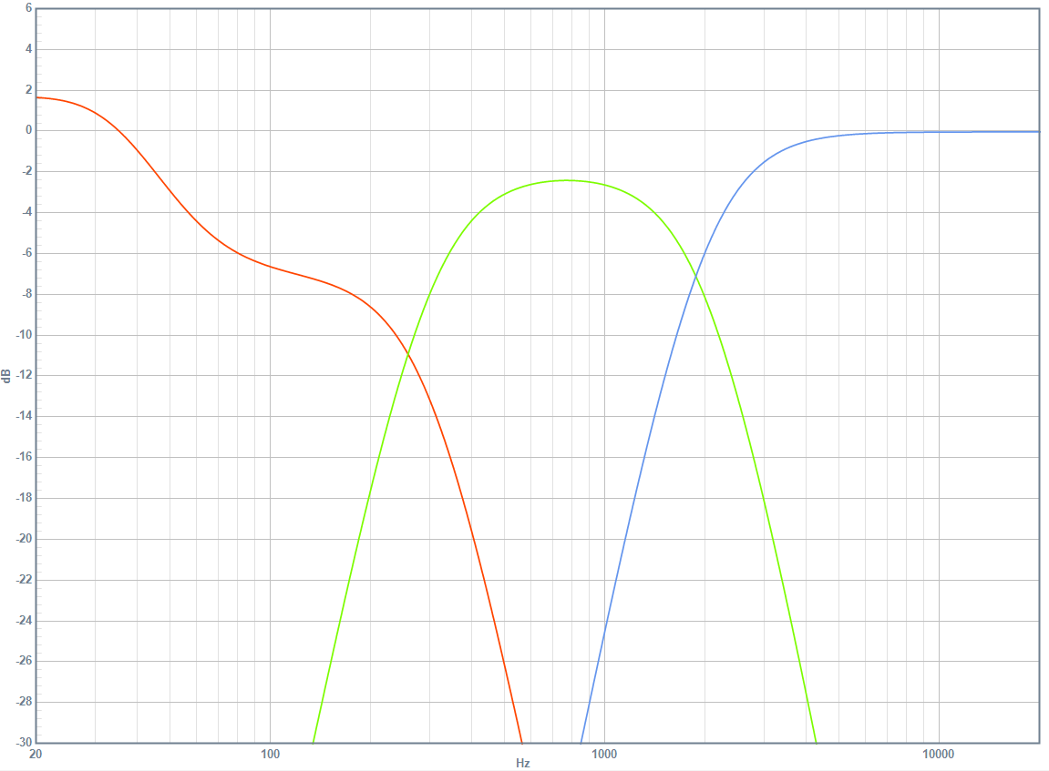
[DSP frequency response with first-try signal chain: woofer (red), midranges (green) and tweeter (blue)]
now let's measure them speakers!
i'm all prepped with HolmImpulse, hearing protection and a calibrated ECM8000.
step one is to scrutinize the tweeter/midrange crossover at 2kHz. this is measured 18" away, on the tweeter's vertical axis, at horizontal angles of 0, 45 and 90 degrees.
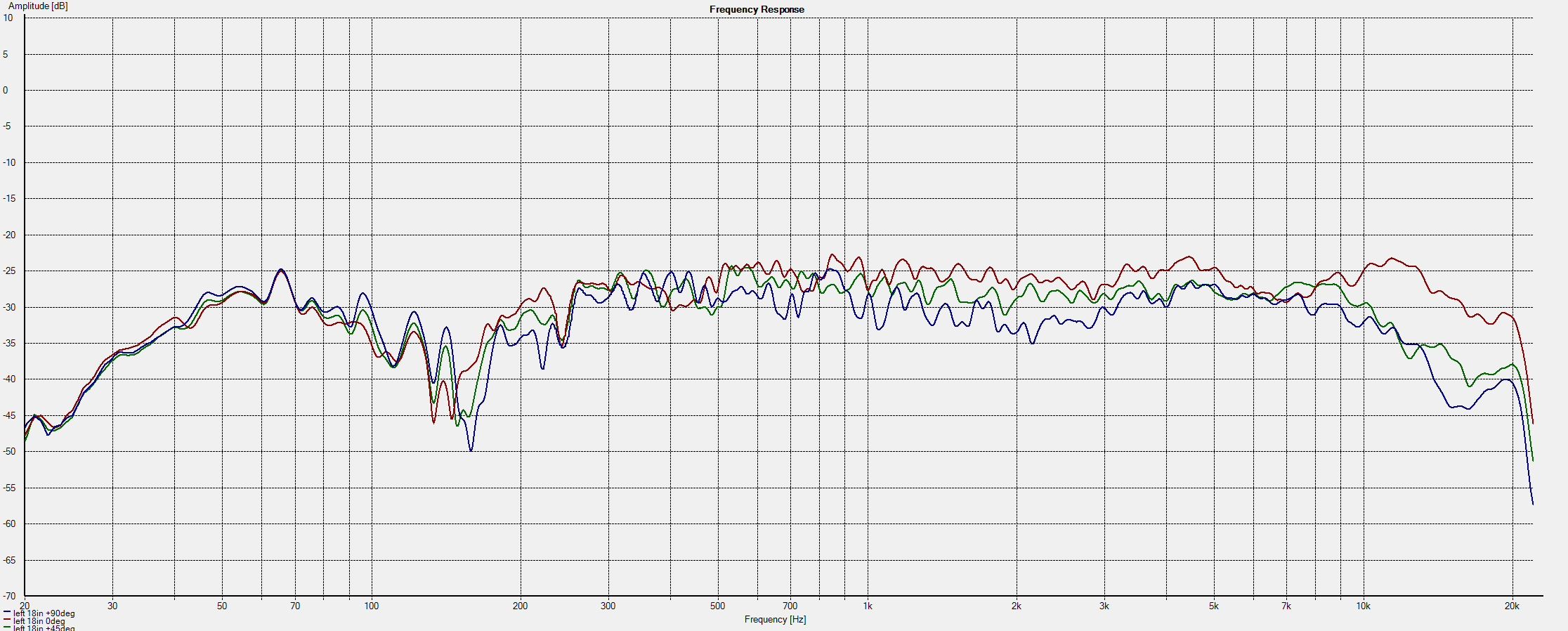
as expected, the 2kHz crossover works alright. off-axis dips at 2kHz are fairly well-controlled due to the tight spacing between tweeter and midrange drivers.
now to examine the 300Hz midrange/woofer crossover. this is measured 2 feet away, between midranges and woofer, at horizontal angles of 0, 45 and 90 degrees.
[eeeeeeeeeeEEEEEEEEEEEE]
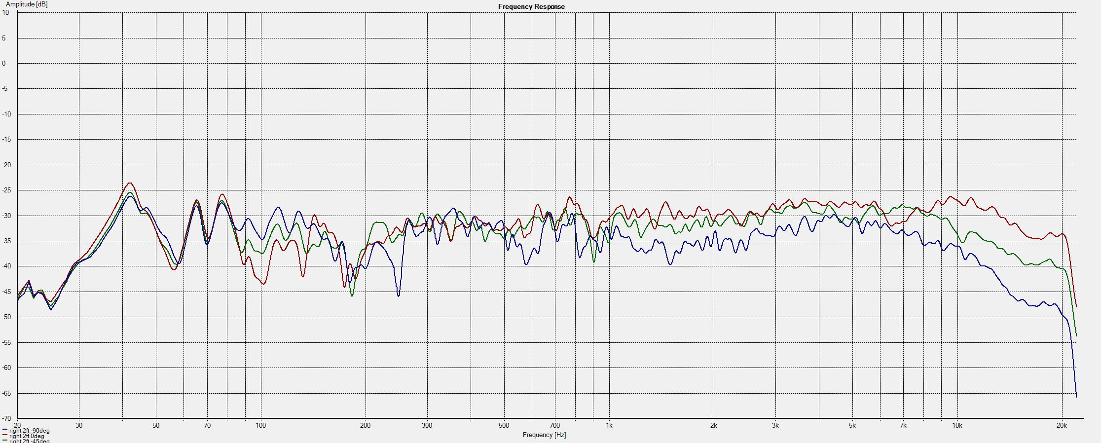
the 300Hz crossover itself is fine. however, we're close enough to the wall to see some lively room modes.
what about measuring from the listening position?
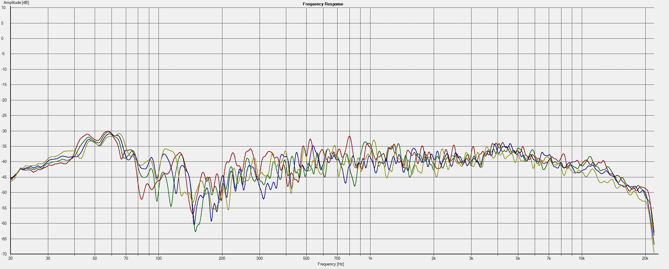
let's measure the response of each speaker at four different positions on the couch.
[the microphone thinks it's people!]
the chassis which holds the DSP must do these obvious, practical things:
it must also do these less-obvious practical things:
so let's analyze these needs in that order.
silent things don't use cooling fans. but amplifiers without cooling fans tend to heat up. we are using Class-D amplifiers of course, but the risk is still real.
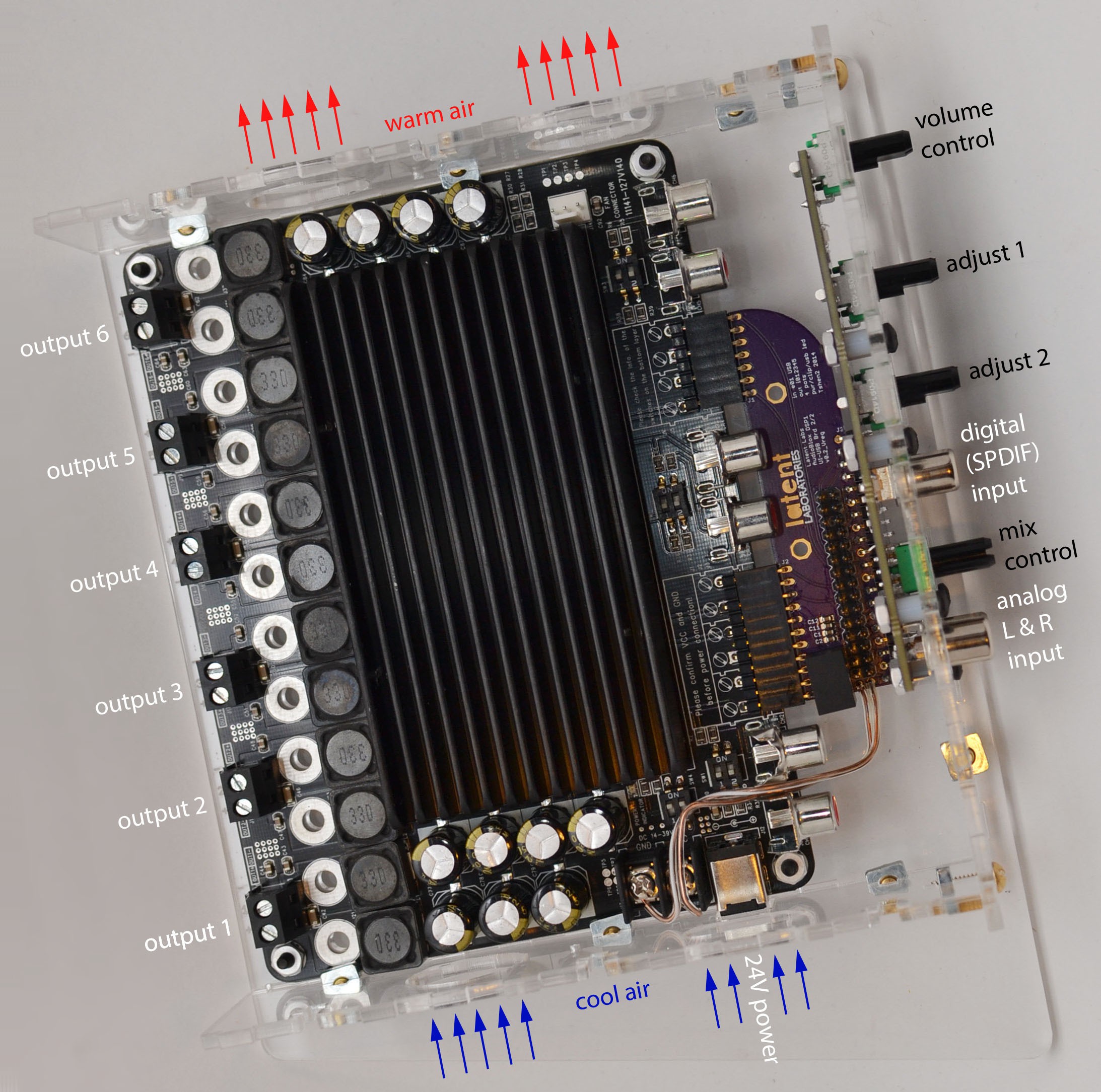
the amplifier board i have picked was built to use a fan, but i am not pushing it anywhere near its rated limits. if i remove the fan, i will be relying on convection to cool the amplifier. the chassis must hold the amplifier upright to maximize convective air flow.
consider the layout of the amplifier & DSP.

[inputs & controls are below and outputs are above. the DC power jack is to the left.]
the amplifier's heat sink must be upright for good cooling, with extensive venting for airflow. hence the DC power jack will be either above or below the chassis. it should clearly be below, or we'd have a power jack sticking out the top of the chassis. the horror!
so here we are:
it has no more internal volume than it needs. that means less surface area, which means less plastic.
acrylic and brass are already beautiful. we will not use glue or paint.
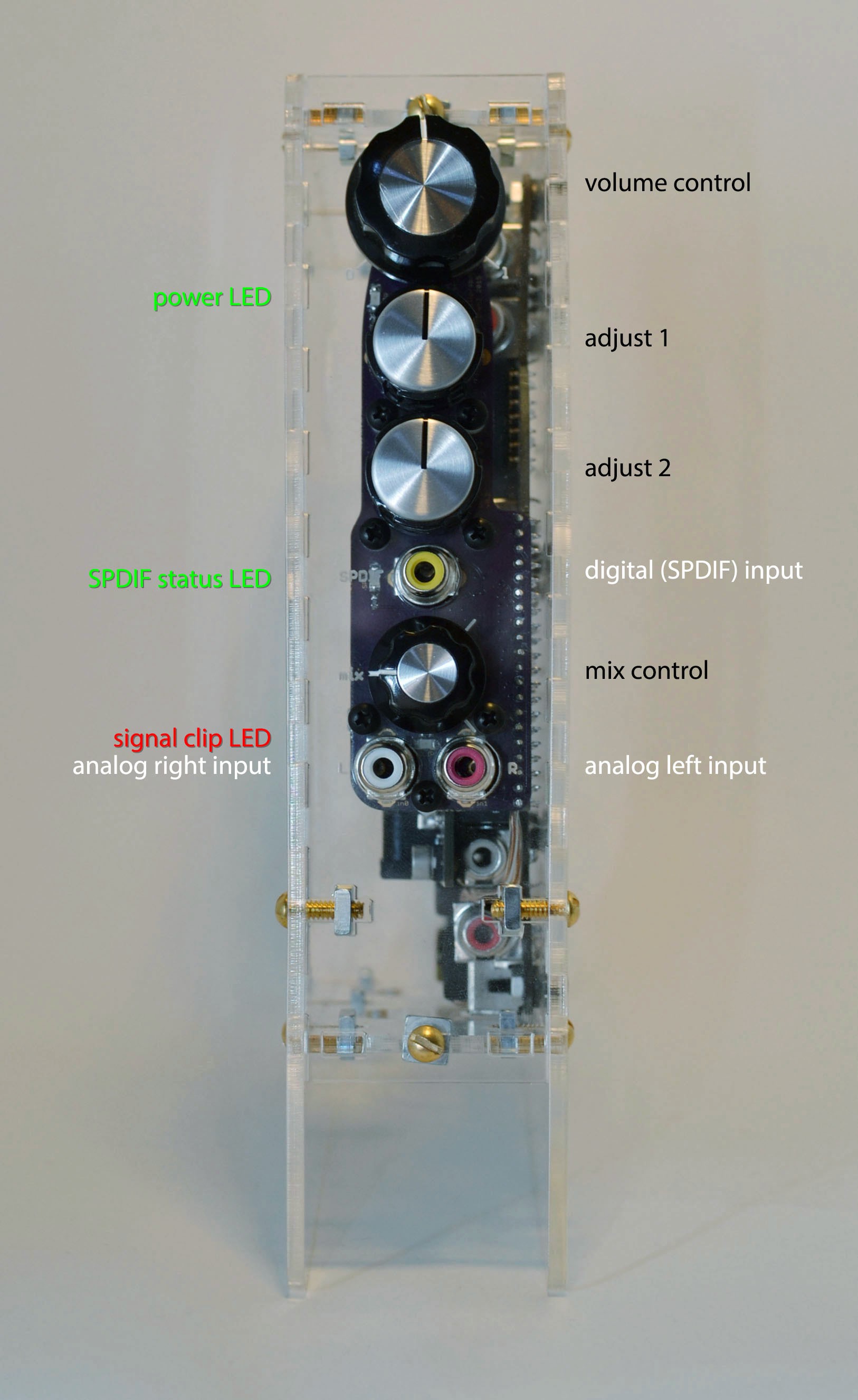
the volume control and mix control knobs both control loudness - they can be the same color.
the multipurpose adjust 1 and adjust 2 knobs will be a different color.
the mix control knob is between the digital & analog inputs. turning it up (towards the digital input) or down (towards the analog input) has the expected effect.
the front panel contains LEDs which indicate power, SPDIF status and analog signal clipping.
the chassis is quite small. it will probably sit on a low table or the floor, between two speakers. it will probably be below the user.
to use the inputs & controls, the user will have to look down at it. it is only polite that it look back up.
the chassis is built as a box with angled feet, so that it looks up by 10 degrees.
various lines on the front-plate are positioned to harmonize and emphasize this angle.

[this is how i see it.]
after all that, what do i end up with? this:
[you can see the venting holes above and below - the lat LAB logo is also a vent.]
so let's install it!
next update: i actually do something with it.
Tshen2 2015
in my last post, i established that the CP2114 doesn't work. so how are we going to solve the synchronous clocking problem, and build a working digital input for the DSP 01?
there's always the brute-force approach - use a high-fidelity asynchronous sample-rate converter. this is a circuit which doesn't care what sample rate (and sample clock) the source is using - it will resample the signal to match the DSP 01's internal clock. after more internet research, i decided to use the CS8422.
the CS8422 is a 24-bit Asynchronous Stereo Sample-Rate Converter. it will accept a digital audio signal at almost any sample rate and resample it to exactly match the DSP 01's fixed 48kHz sample clock. while the CP2114 has a USB input, the CS8422 uses SPDIF, which i have certainly played with before.
so here's what we've got:
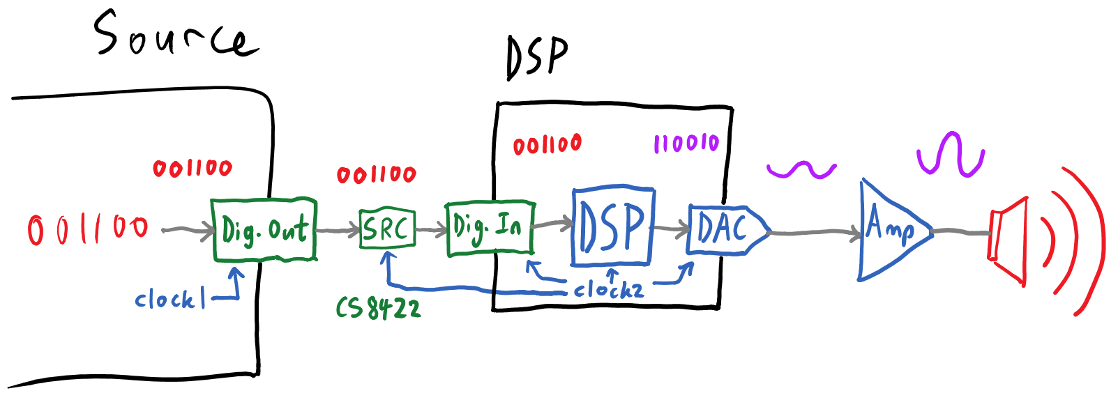
now the digital input should be resampled to match the DSP 01's internal clock (clock2), but does it really work? let's build a board to connect them!
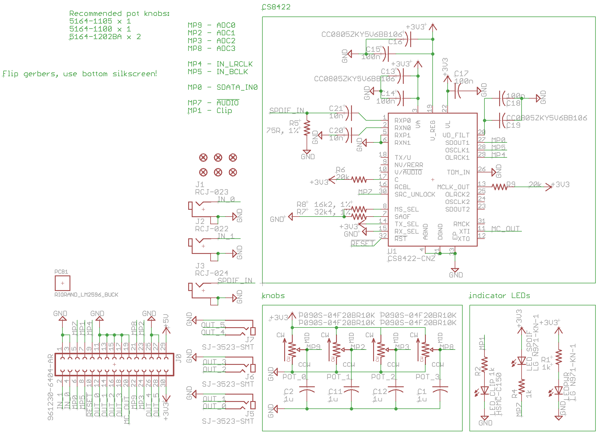
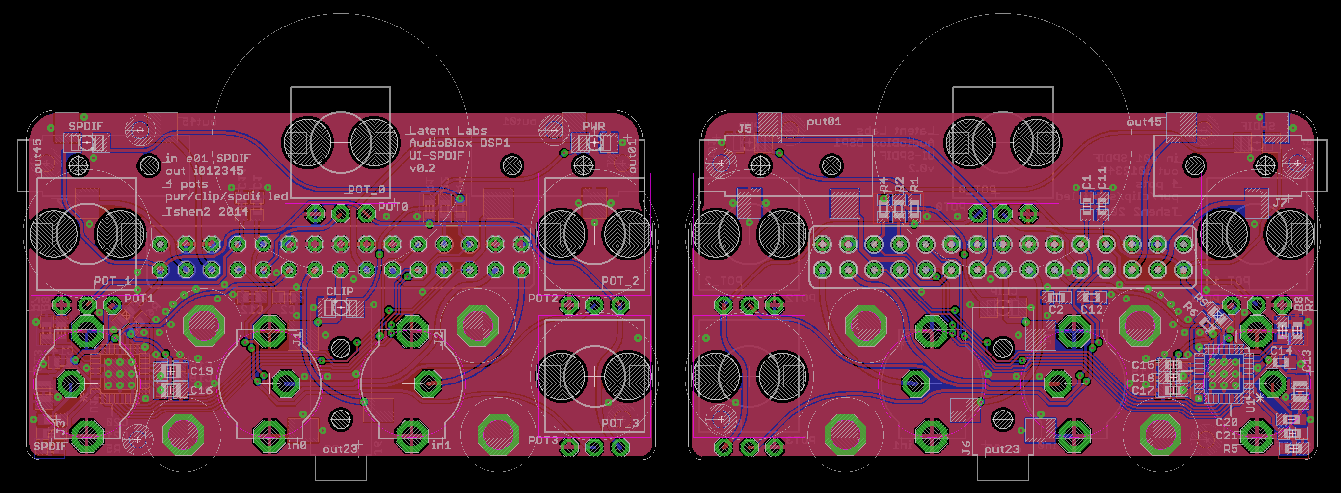
..i didn't even take a photo of that one. but whatever, it worked. which allowed me to make a much better one, as you shall see.
time and time again, i have found that connectors are the bane of my existence. they're bulky, expensive, ugly and time-consuming. even the first DSP 01 project used 3.5mm-to-RCA audio cables & connectors for internal hook-up, and that doubled the size of the chassis. how could i entirely purge ugly internal connectors from my next project?
the objective - to connect a DSP 01 board to a 6-channel power amplifier and a front-facing instrument panel. instead of RCA jacks, i'd link everything with 0.1" headers. they would go together like this:
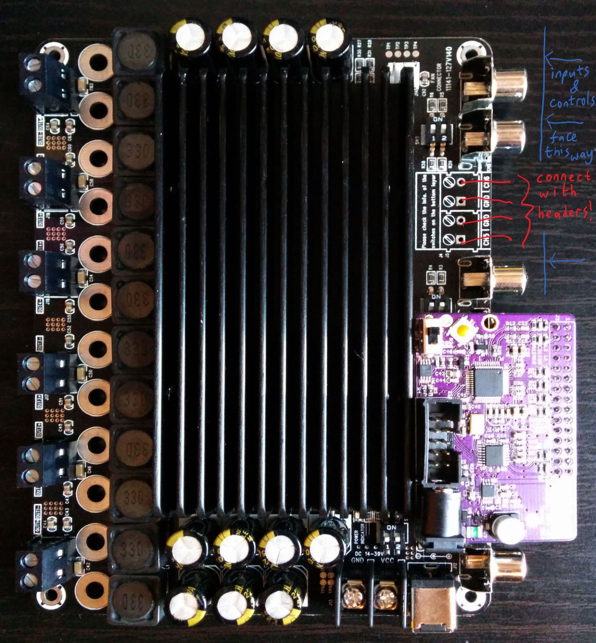
the amplifier & DSP 01 would connect to a horizontal backplate, but the controls & inputs needed a vertical front panel. i'd have to build two boards and connect them at right-angles.
time for 3D PCBs!
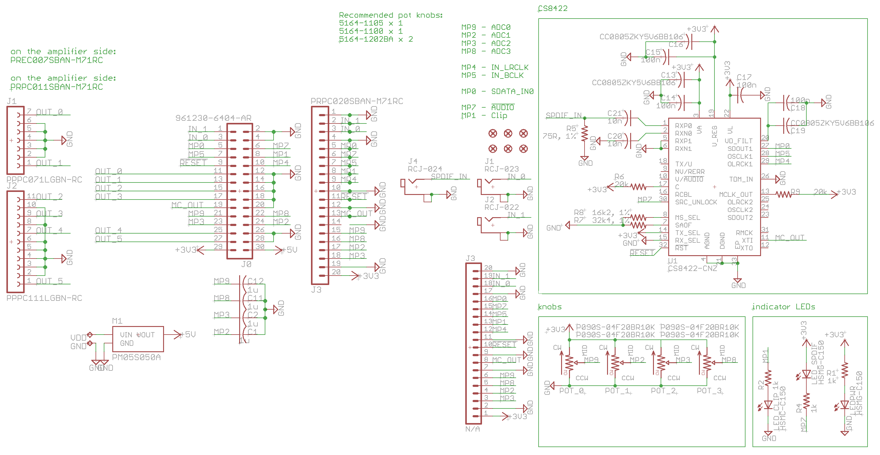
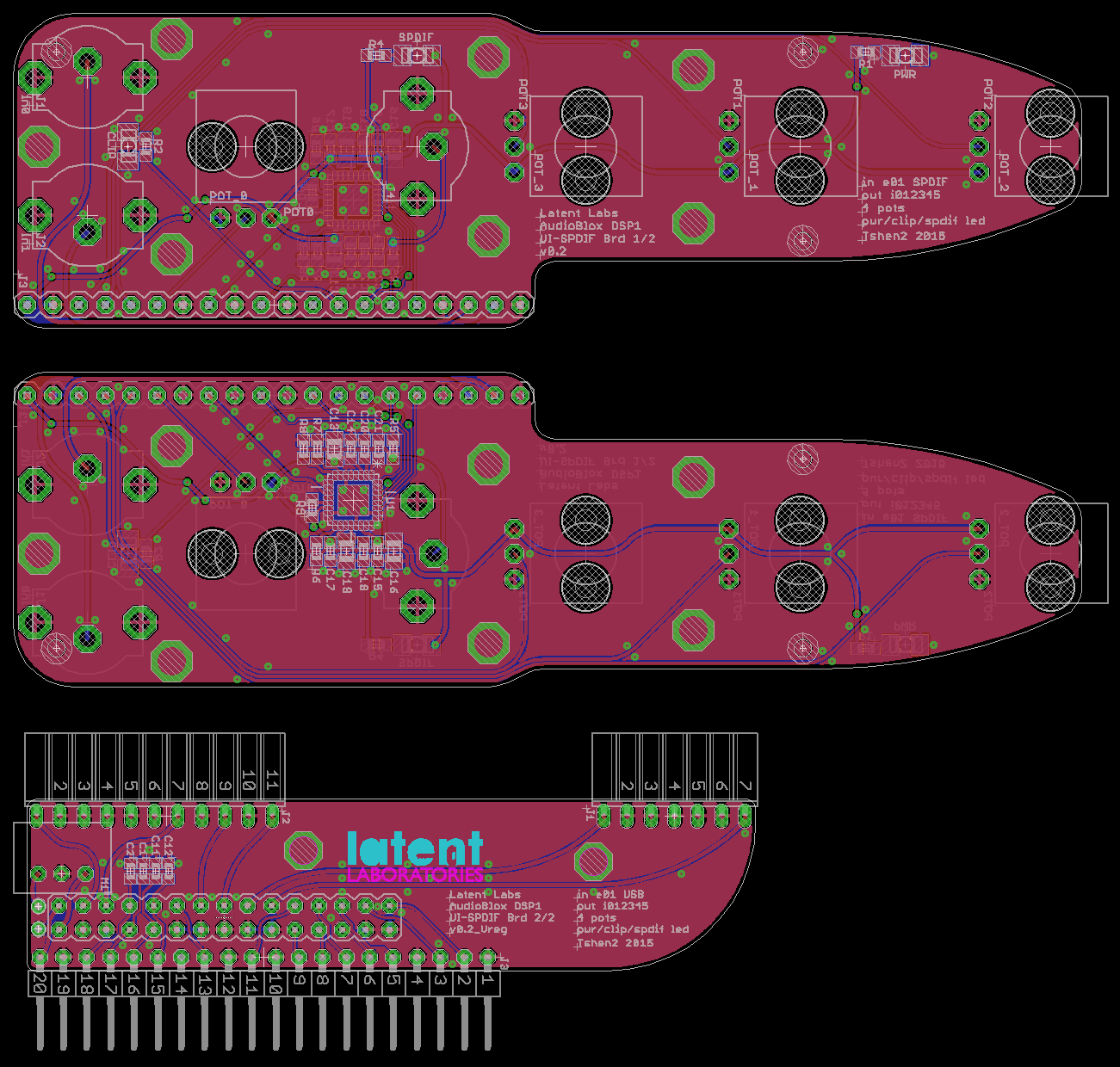
[PCB layout: control panel front (upper) & back (center), orthogonal backplate (lower).]
[the small box on the left is a 5V switching regulator. this lets the DSP 01 run on the same 24V supply voltage as the 6-channel amplifier.]
and now to put it together.
i think it's quite pretty.
next update: a moment of art & industrial design.
Tshen2 2015
if you're playing music from your computer, and it's coming out of amplified speakers, the signal chain probably looks like this:
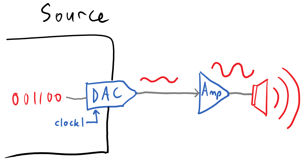
the music is stored digitally in your computer. it gets converted to analog audio by the digital-to-analog converter (DAC) which is in your soundcard (or external). the analog audio is embiggened by the amplifier, which then pushes your speakers.
When you stick a DSP in the middle, the picture looks a bit more stupid.

as before, the music is stored digitally, and is converted into analog audio by the DAC. but the DSP only understands digital audio, so you need an analog-to-digital converter (ADC) to convert the analog signal back into digital. and after the DSP has done its work, you need another DAC to go back to analog. this is not good because every converter degrades the audio signal. why can't we remove the first DAC and ADC, and send digital audio directly into the DSP?
the main problem is synchronous clocking - both the transmitter and receiver must be using the same clock. here, the source is using clock1 and the DSP is using clock2. you cannot simply force the DSP to use clock1, because all the DSP's frequency filters are controlled by its clock, and clock1 can be very inconsistent! if clock1's frequency shifts by 2%, the DSP's frequency filters will shift by 2%. if clock1's frequency is 44.1kHz when the DSP is expecting 48kHz, things could get very, very broken.
while journeying through the intertubes, i found a potential solution - the CP2114 by Silicon Labs. it is a 'USB-to-I2S Digital Audio Bridge', i.e. a chip which connects to your computer's USB port, and speaks a digital audio protocol (I2S) which the DSP understands. how does this solve the 'different clocks' problem?
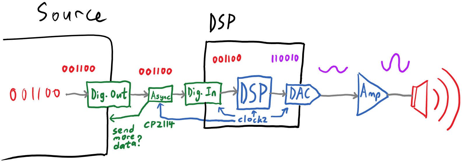
the CP2114 is an 'asynchronous' USB audio device. this means a few things:
in this scheme, it doesn't matter that the source and DSP don't share the same clock. the source is forced to resample and transmit the data at 48kHz, and if its clock doesn't match up exactly with the CP2114's clock, the CP2114 can tell it to slow down or speed up.
as for bit-depth, the CP2114 only supports 16-bit audio, which is rather low. however, it also supports sending 'volume control' information as a separate 8-bit signal. since the main advantage of 24-bit audio vs. 16-bit audio is having more bits to throw away for dynamic range, that separate 8-bit volume control makes the low bit-depth more palatable.
so - let's make a board to plug the DSP 01 into a CP2114.
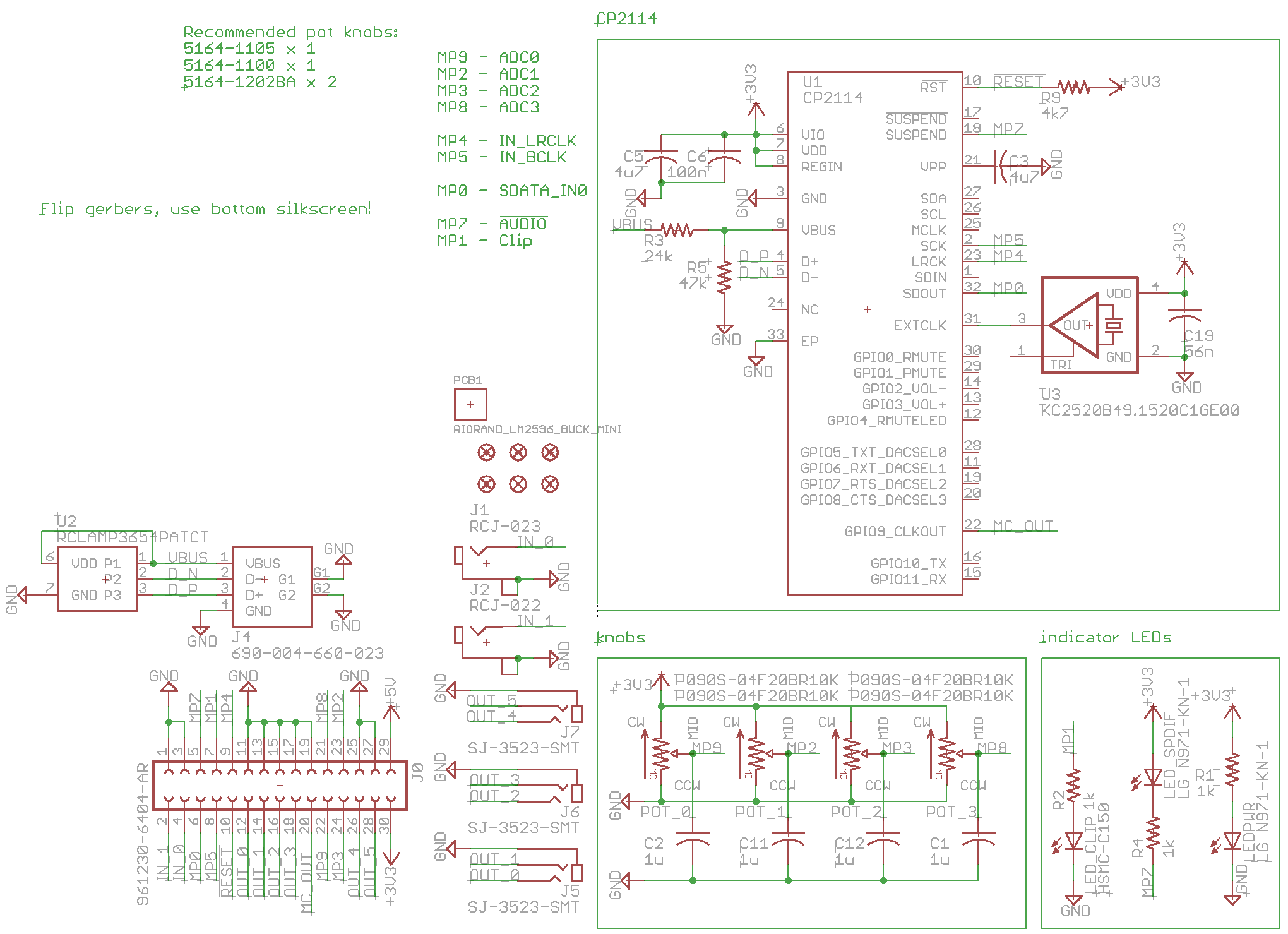
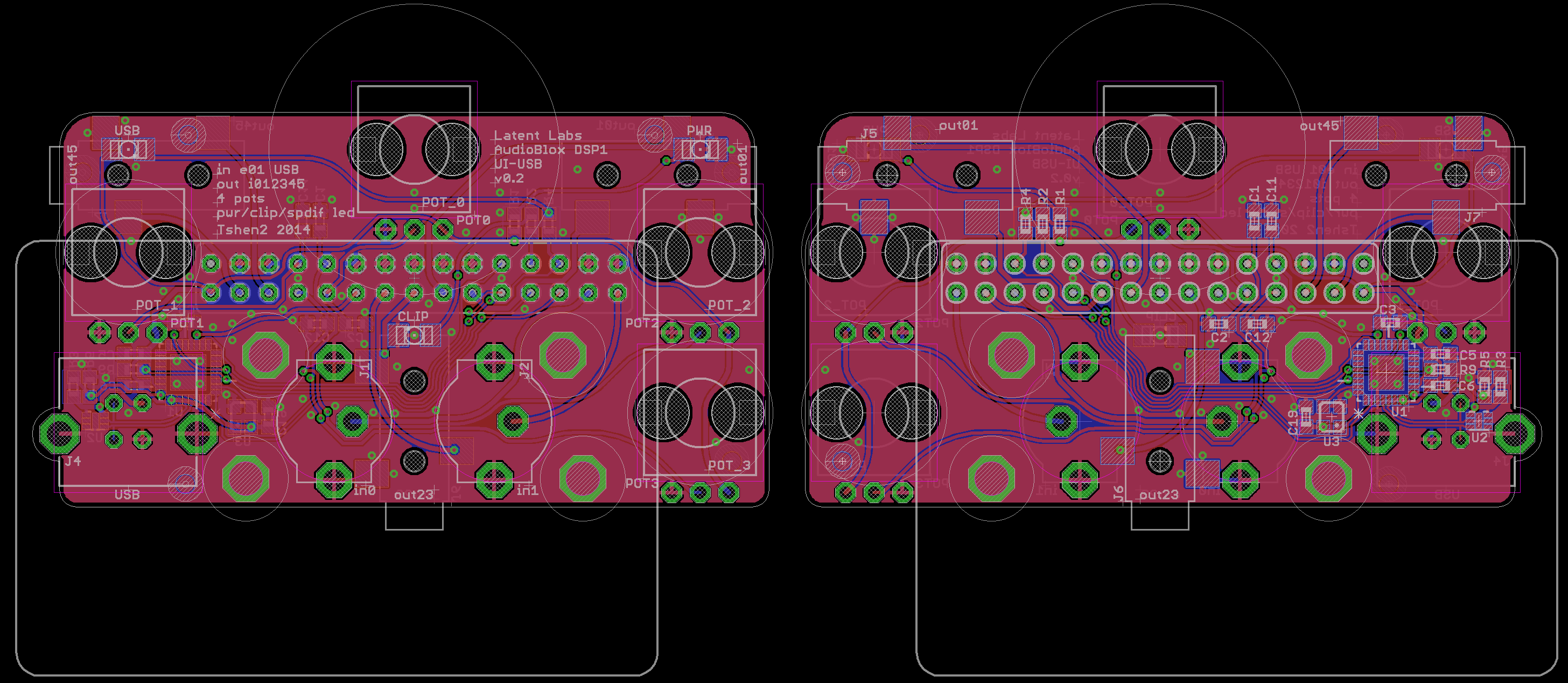
[PCB layout - front (left) & back (right).]
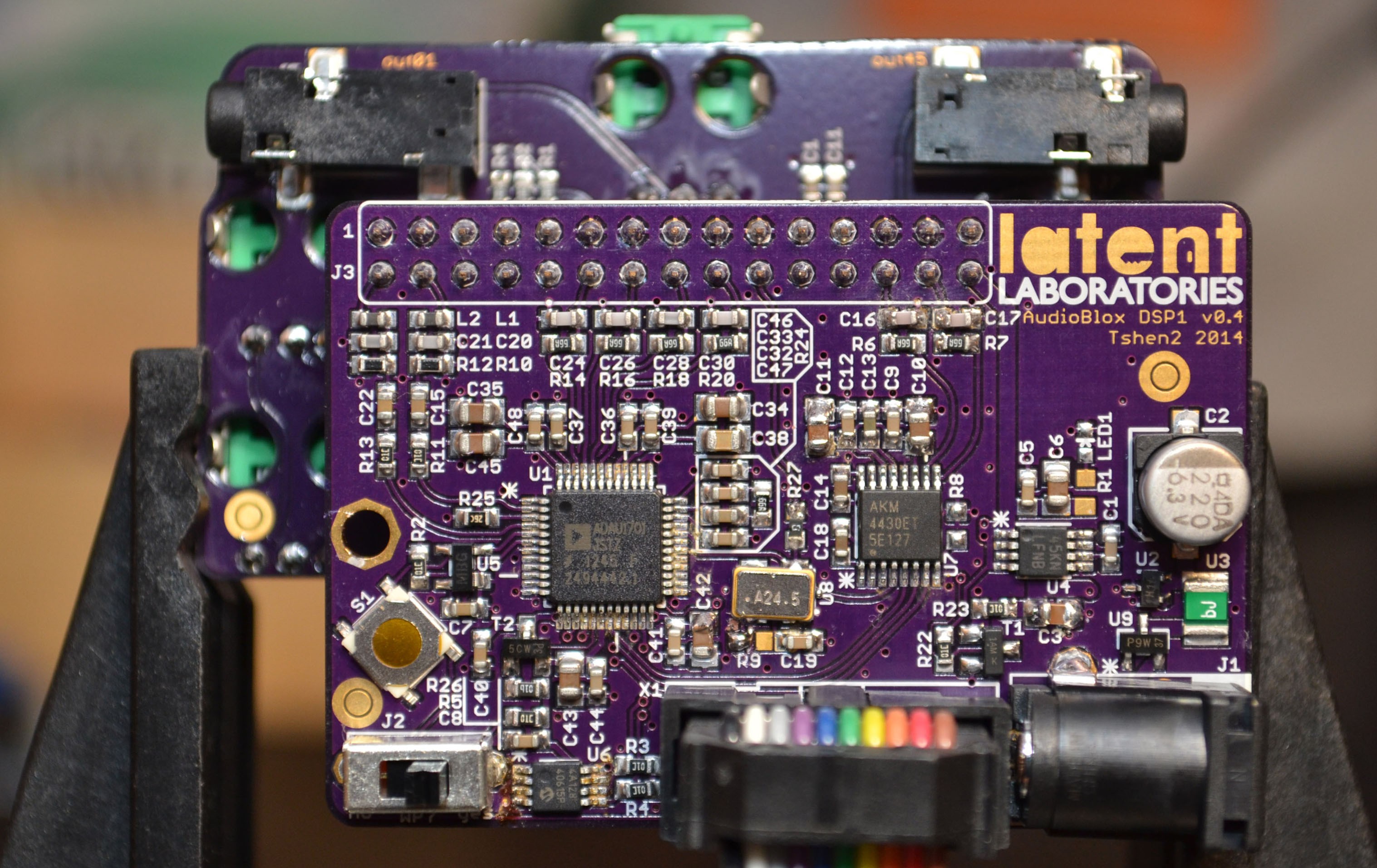
does it work? nope.
the DSP 01 wants a 24.576MHz clock signal. in order to produce that clock, i put a 49.152MHz clock on the CP2114 board (pictured above) and tried to use the CP2114's internal clock dividers to halve that clock to 24.576MHz for the DSP 01. the problem is, the CP2114's clock dividers only work when the CP2114 is connected to a computer's USB port. the DSP 01 wouldn't be able to run at all if no USB source was present.
so i redesigned the board, this time with an external clock divider (using a D-flipflop):
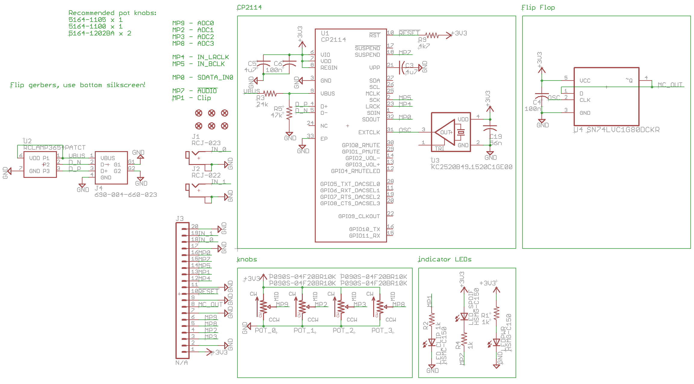
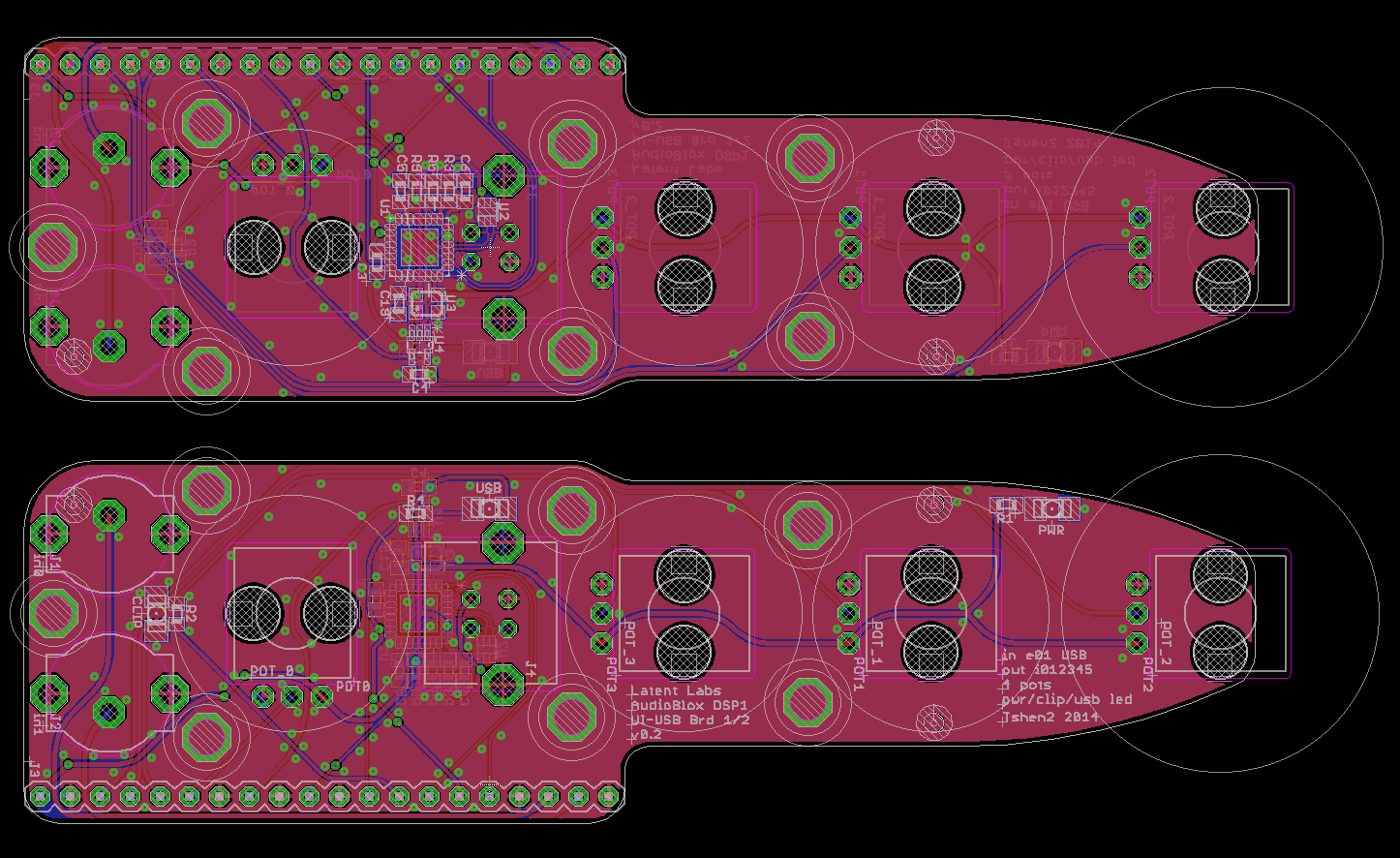
[PCB layout - front (lower) & back (upper).]
does it work now? still nope.
but why?
as i've mentioned, the CP2114 is supposed to be a 'USB-to-I2S Digital Audio Bridge'. the DSP 01 accepts digital audio input through an I2S bus, so I assumed they'd be able to talk to each other. the thing is.. the CP2114 does I2S wrong.
here is a screenshot from the I2S spec:
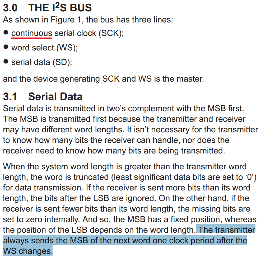
let's pay attention to these two points:
now, let's compare this...
Read more »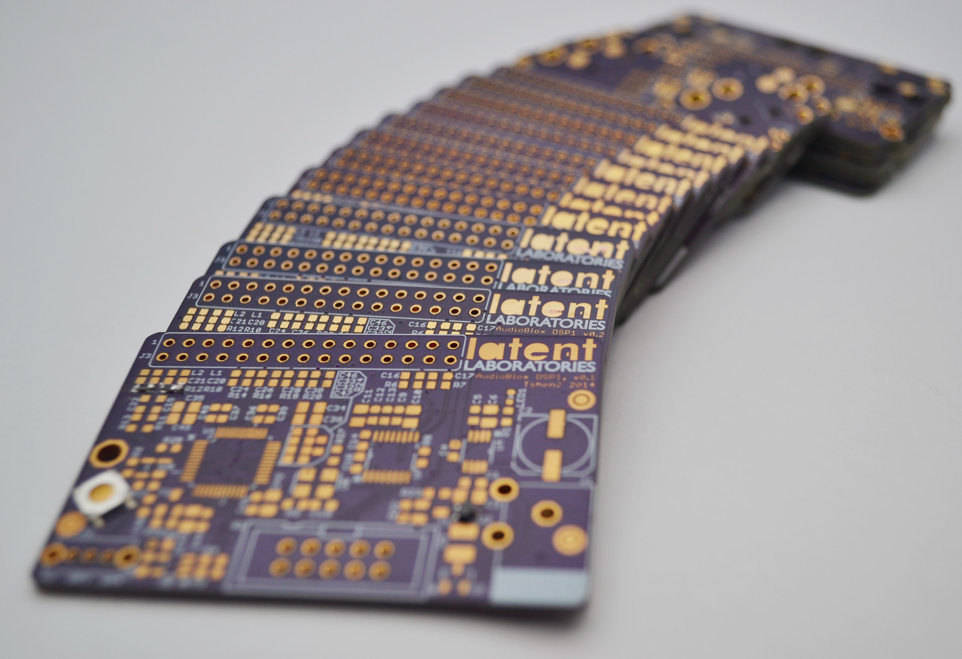
i've decided to make DSP 01 an open source project.
you can find all the files here.
this is not one of those open source projects where i misdirect you to an indecipherable Github folder. i've organized my files in a clear way. i want you to be able to see exactly what i did, how i did it, and how to do it yourself.
i've put all my design files on an open source page where you will find everything you need to build yourself a DSP just like this one. you are welcome to.
the faster i give away these projects, the less reason i have to stand still. it's not like i will sell it anyways - i already have a (massive) day job, and much bigger ideas to chase. so this one is for you - build it, learn from it, use it everyday.
there are no strings attached. this is a gift.
Tshen2 2014
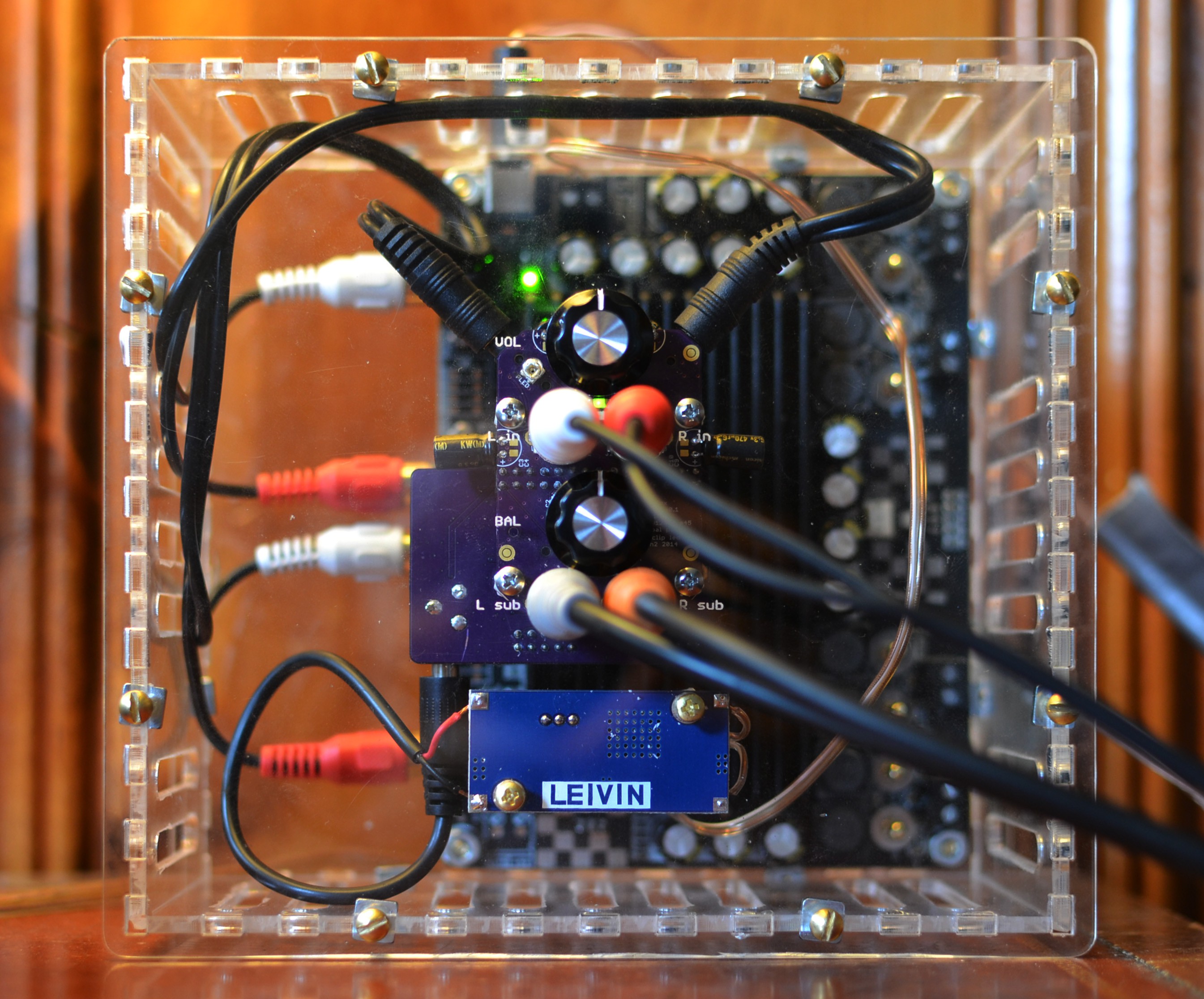
i appear to have a DSP. time to set it up!
first, the basics:
here's the architecture again:
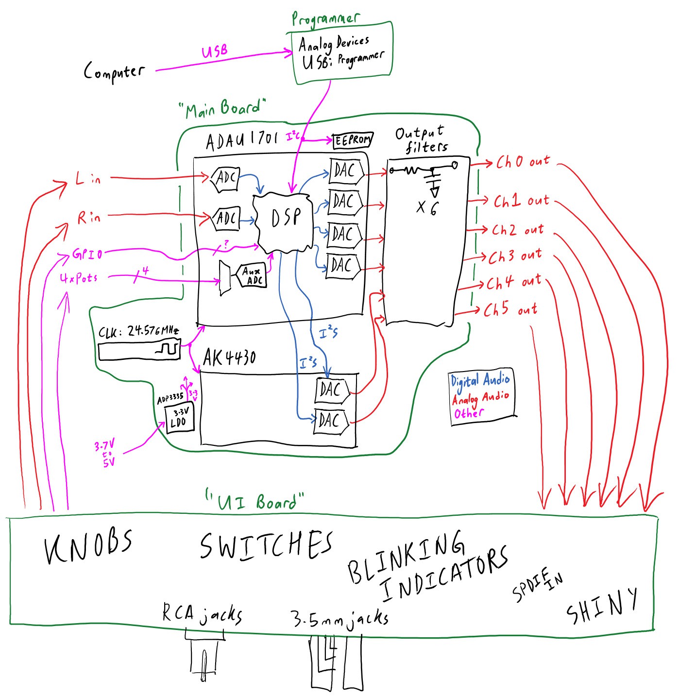
(DSP architecture, version 2 - final)
as you can see, both ADCs and four DACs are built into the ADAU1701 itself. they communicate directly with the DSP core using internal Analog Devices magic. setting them up is easy!
the two DACs in the AK4430 are more troublesome. they are supposed to receive digital audio through stereo I2S. i have zero prior I2S experience, so this is a bit of a bumble-thon.
I2S seems to need these signals:
the AK4430 also wants the 24.576MHz master clock so it can jostle its switch-cap filter, as mentioned in part 2. the master clock can be wired right in. but how do we generate the other signals?
the ADAU1701 datasheet has the answer on page 46:
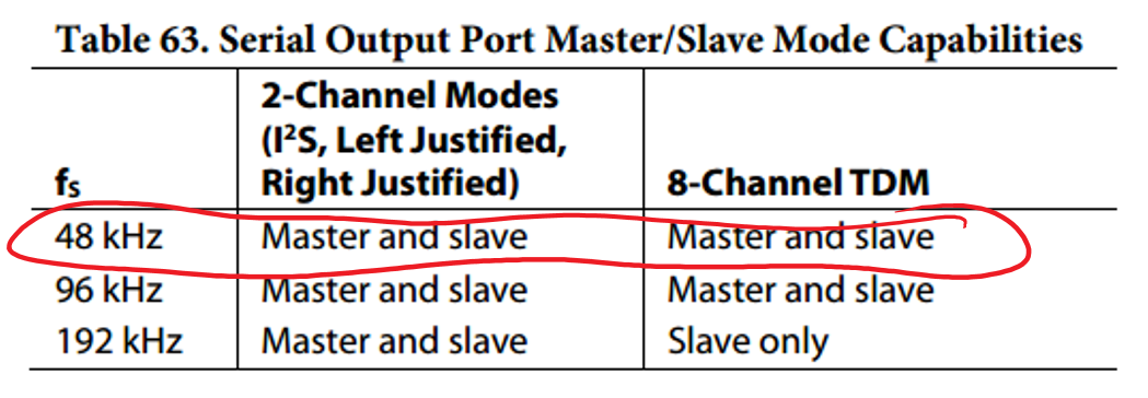
(at 48kHz sample rate, the ADAU1701 can be the I2S master.)
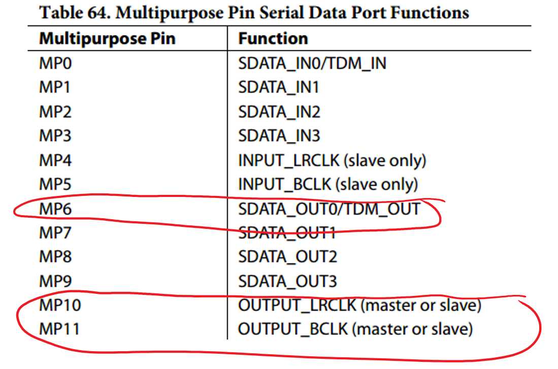
(the general-purpose IO pins, MP6, MP10 and MP11 can be our I2S bus)
all DSP programming is done through the SigmaStudio software from Analog Devices. it is a beautiful example of flow-based programming, which is a great way to think about signal processing chains.
so let's set up the I2S bus!
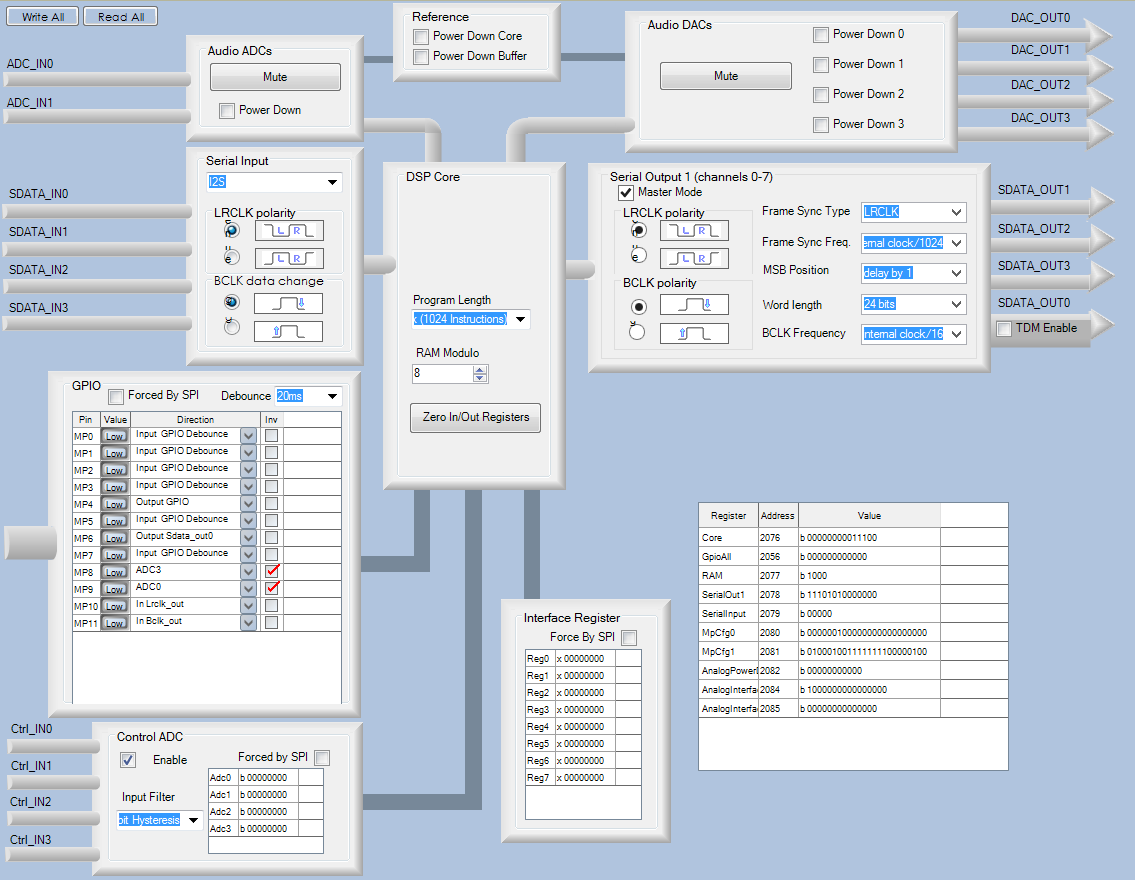
(that 'Serial Output 1' box contains everything we need to know)
why is the left-right clock (aka 'Frame Sync' clock, aka 'LRCLK') set to 'internal clock/512' = 48kHz? well, 48kHz is our sample rate. at every sample, we have to first send some right-channel data (with LRclock low) and then some left-channel data (with LRCLK high). that means, repeating at 48kHz, LRclock must spend some time low and some time high. so that is a 48kHz square wave!
and why the bit clock (aka 'BCLK') set to 'internal clock/8' = 3.072MHz? well, it's transmitting stereo 24-bit audio. that means it has to transfer two 24-bit integers (at least 48 BCLK cycles!) for every audio sample. let's allocate 64 BCLK cycles per audio sample. if a clock is 64 times faster than our sample rate (48kHz), that's 3.072MHz.
UPDATE: for some strange reason, in order to get the 48kHz sample rate, you need to set 'Frame Sync' frequency to 'internal clock/1024' and BCLK to 'internal clock/16'. it doesn't make sense, but that's what works. The image above has been changed accordingly.
as for the LRCLK and BCLK polarity, that's taken straight from the AK4430 datasheet.
now let's look at the GPIO (general purpose IO) configuration:
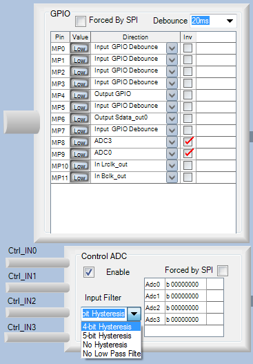
for I2S communication with the AK4430, general purpose IO pins MP6, MP10 and MP11 are set to SDATA_OUT0, LRCLK_OUT and BCLK_OUT respectively.
to read the position of the two control knobs (Volume & Balance), pins MP8 and MP9 are set to the inputs of the 8-bit auxiliary ADC: ADC3 and ADC0.
to control the clip-indicator LED, pin MP4 is set to Output GPIO.
next, how do we set up the EEPROM?
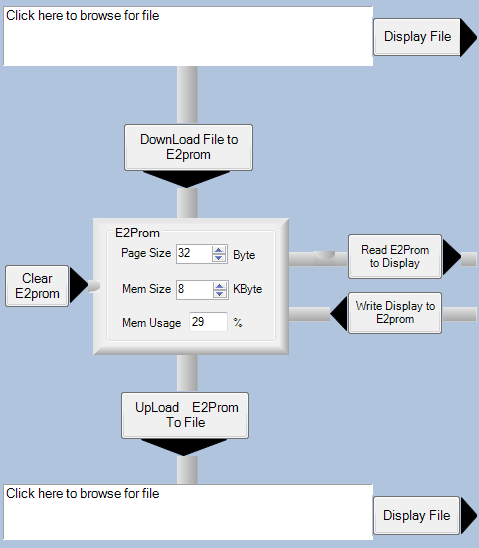
the DSP uses a 24FC64FT EEPROM from Microchip. it has a capacity of 64kb, which is 8kB, so that is how i set up my Mem Size. the datasheet lists a '32-Byte Page Write Buffer', so i have set Page Size to 32 Byte.
now that this thing is set up, i can finally doing something with it.
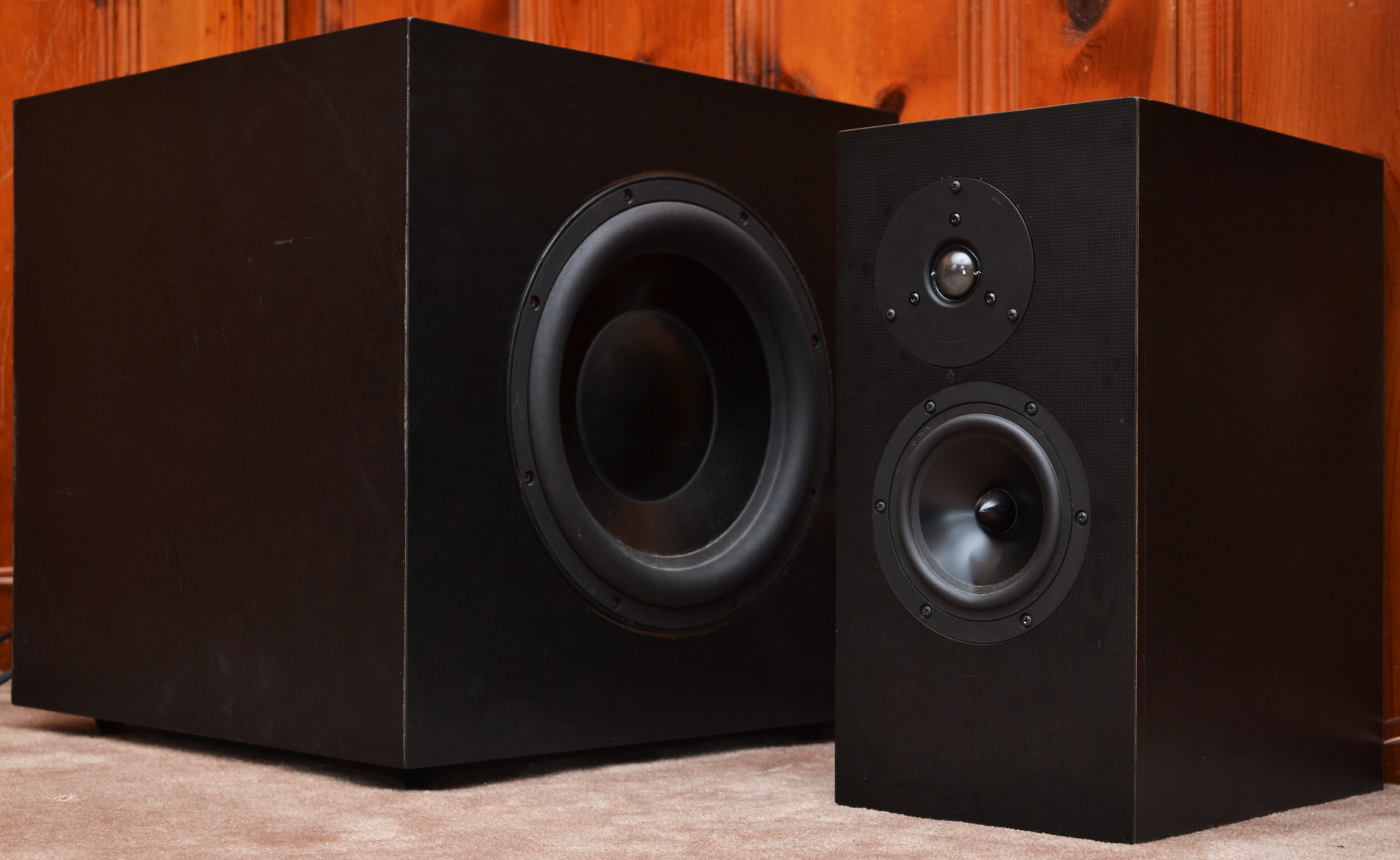
these are the first speakers i ever built. on the left is a 12-inch subwoofer using a Dayton Reference driver and an M&K plate amplifier. on the right is one of the two biamplified main speakers, using Dayton tweeters and woofers. i will program DSP 01 to be an equalizer & crossover for the entire system, with the internal 4x100W amplifier driving two tweeters and two woofers, and the two line-level outputs controlling the subwoofer through the M&K plate amplifier.
but that is too much for all at once! first of all, let's get it working with just one main speaker.
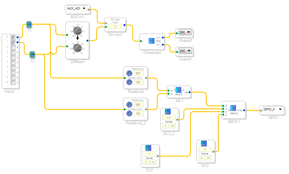
here is the signal flow for controlling one main speaker.
the lower branch (starting with PeakEnv2 and PeakEnv2_2) checks if the DSP's...
Read more »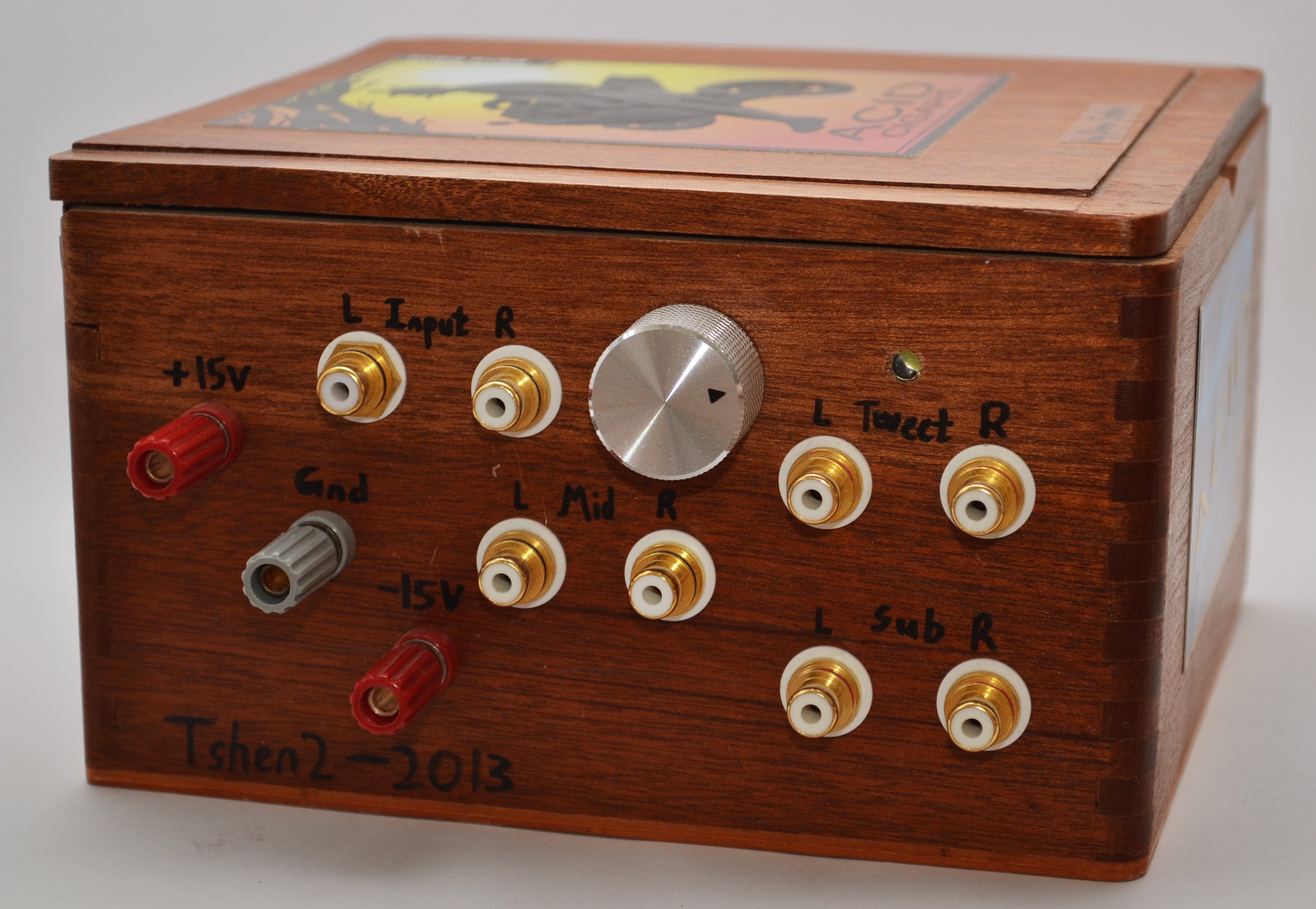 (analog signal processor, front panel, circa 2013)
the single biggest difference between 'hacky' and 'solid' audio gear is the box it comes in.
this isn't just vanity. well-constructed equipment lasts, which justifies its cost in cash and time. you won't worry when you move it. you won't worry when you touch it. the interconnects won't wiggle out of place, the volume control won't crackle or free-spin. the bloody thing won't catch fire.
if it's performing for you, or you're performing with it, it won't give up, turncoat and die.
it is a real pity that most hackers half-ass their boxes. above is my own attempt, in 2013, to turn a cigar box into an electronics chassis. there's no symphony to the position of anything. it's hacked together in all senses of the word.
the inside is worse.
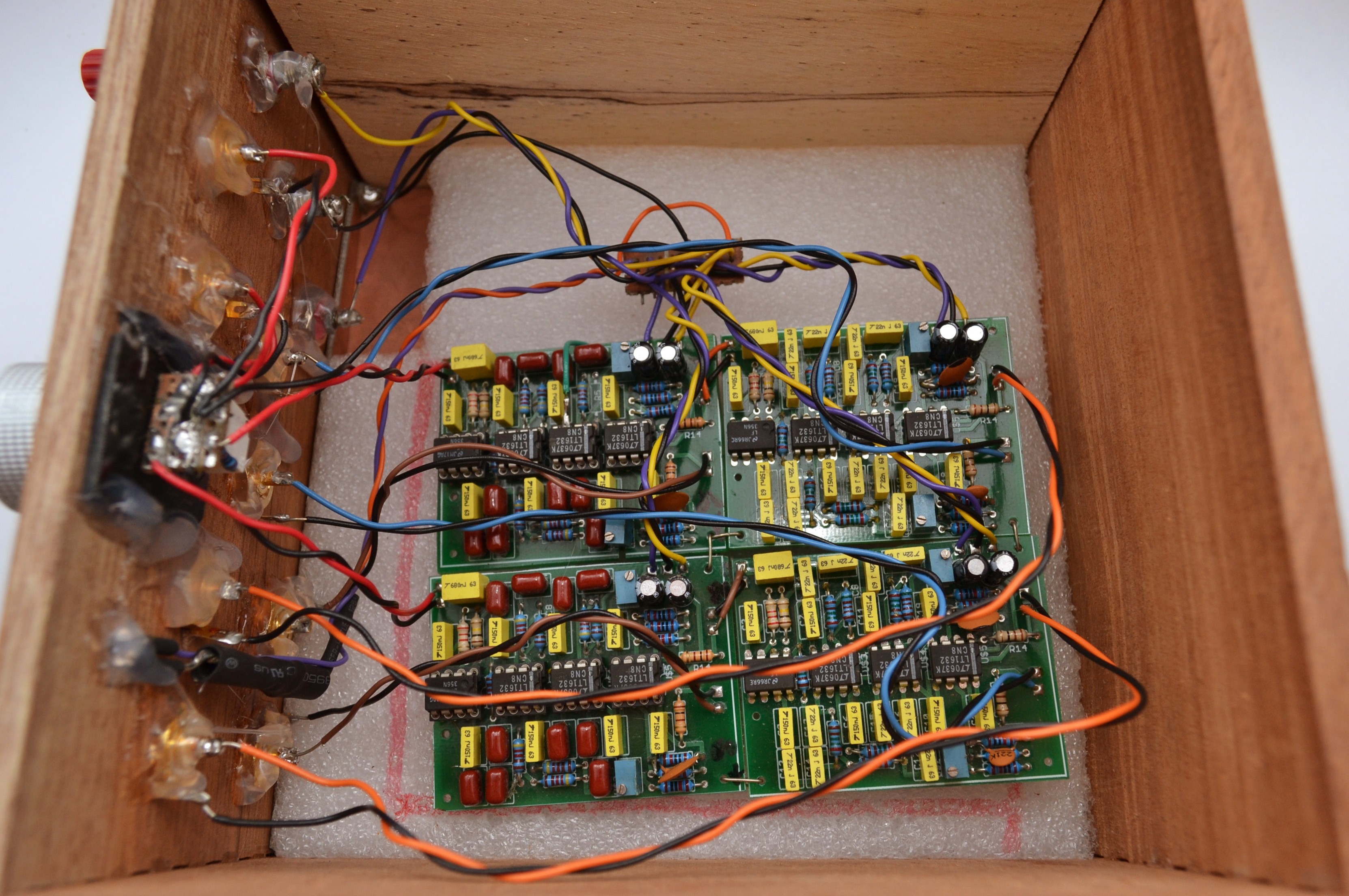 (analog signal processor, inside view, circa 2013)
are the circuit boards anchored by the tension of the wires? yes.
are the jacks Loctite-ed with hot glue? yes.
is the volume pot protoboarded and bolted to scrap plastic? yes.
is every input and output tight-roped on unshielded wires? yes.
this isn't even all. there were two stereo amplifiers and three separate power supplies, all with their own hacked-up boxes, and cables strung in between.
it even took ages to hand-cobble this disaster. i'd completely overlooked mechanicals during the design phase. here was the result. never again.
DSP 01 would be a singular, hyper-integrated thing. i would nestle the user interface, DSP core and quad-channel amplifier board into a single box. one 24V power supply would power the amplifiers as well as the DSP, through a 5V buck regulator.
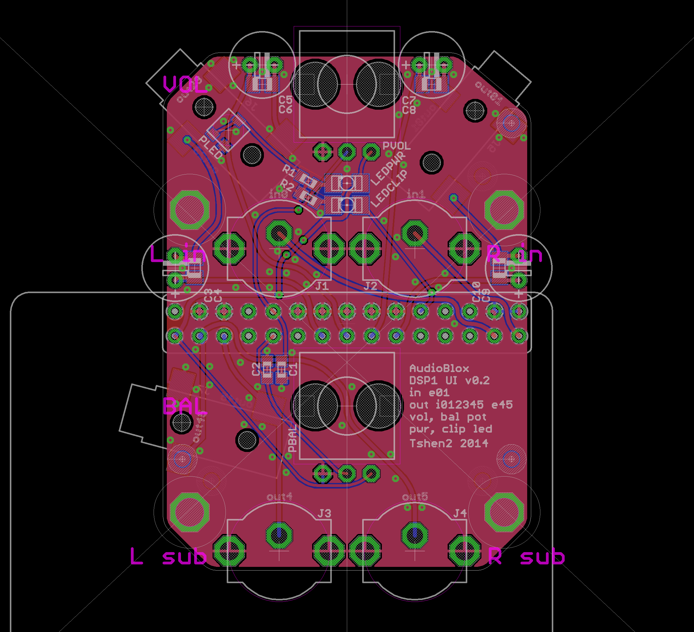 (UI board, version 1)
the UI board plugs directly into the main DSP board, giving it RCA inputs, RCA/3.5mm outputs, two adjustment pots and indicator lights. i added a tiny knob to dim the power light. i lasercut holes in the front panel with my mechanical Eagle CAD technique, to exactly fit the pots and RCA jacks. the amplifier's heat sink would orient vertically to maximize passive cooling.
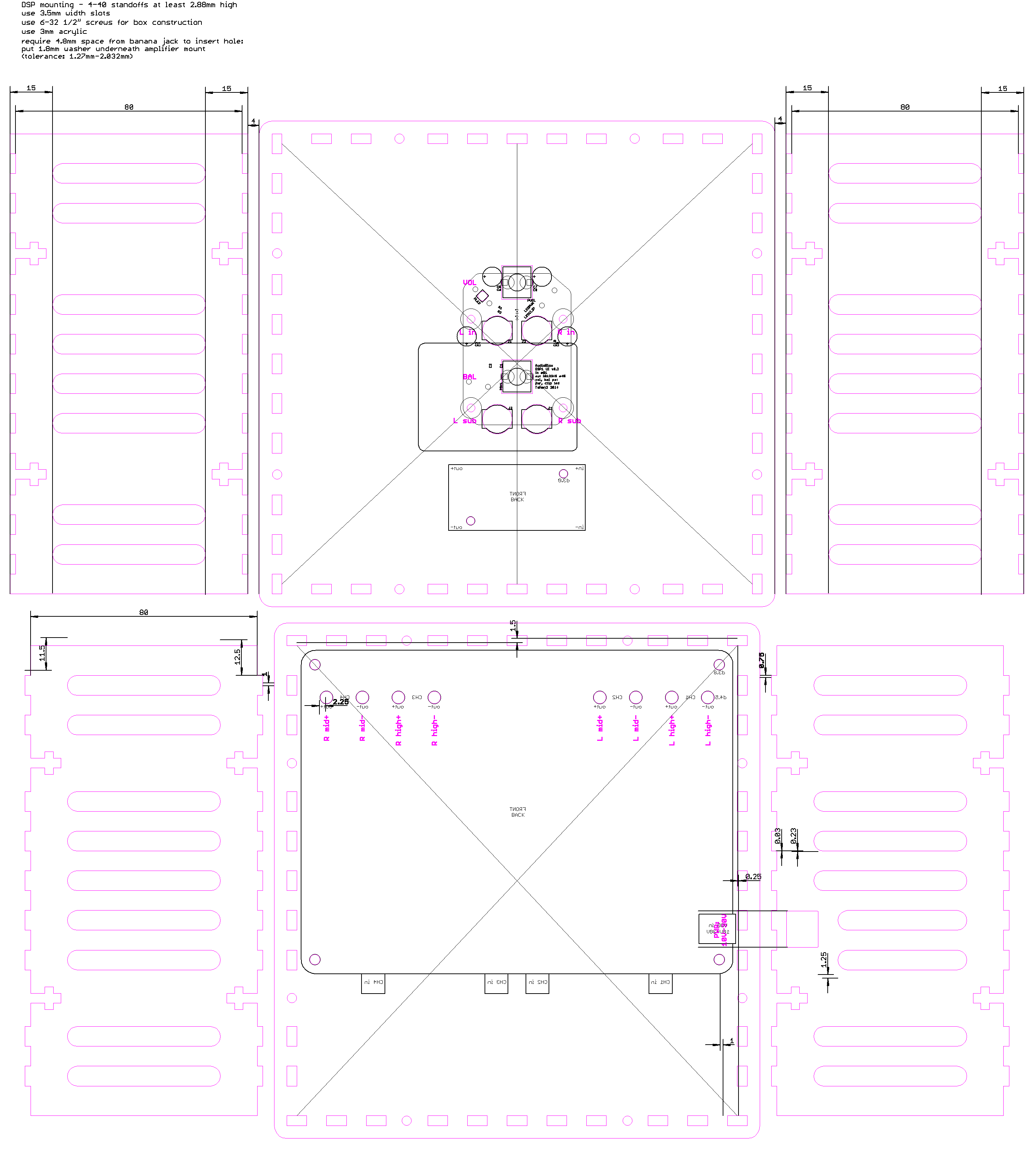
(the entire lasercut assembly)
then i went to lasers.
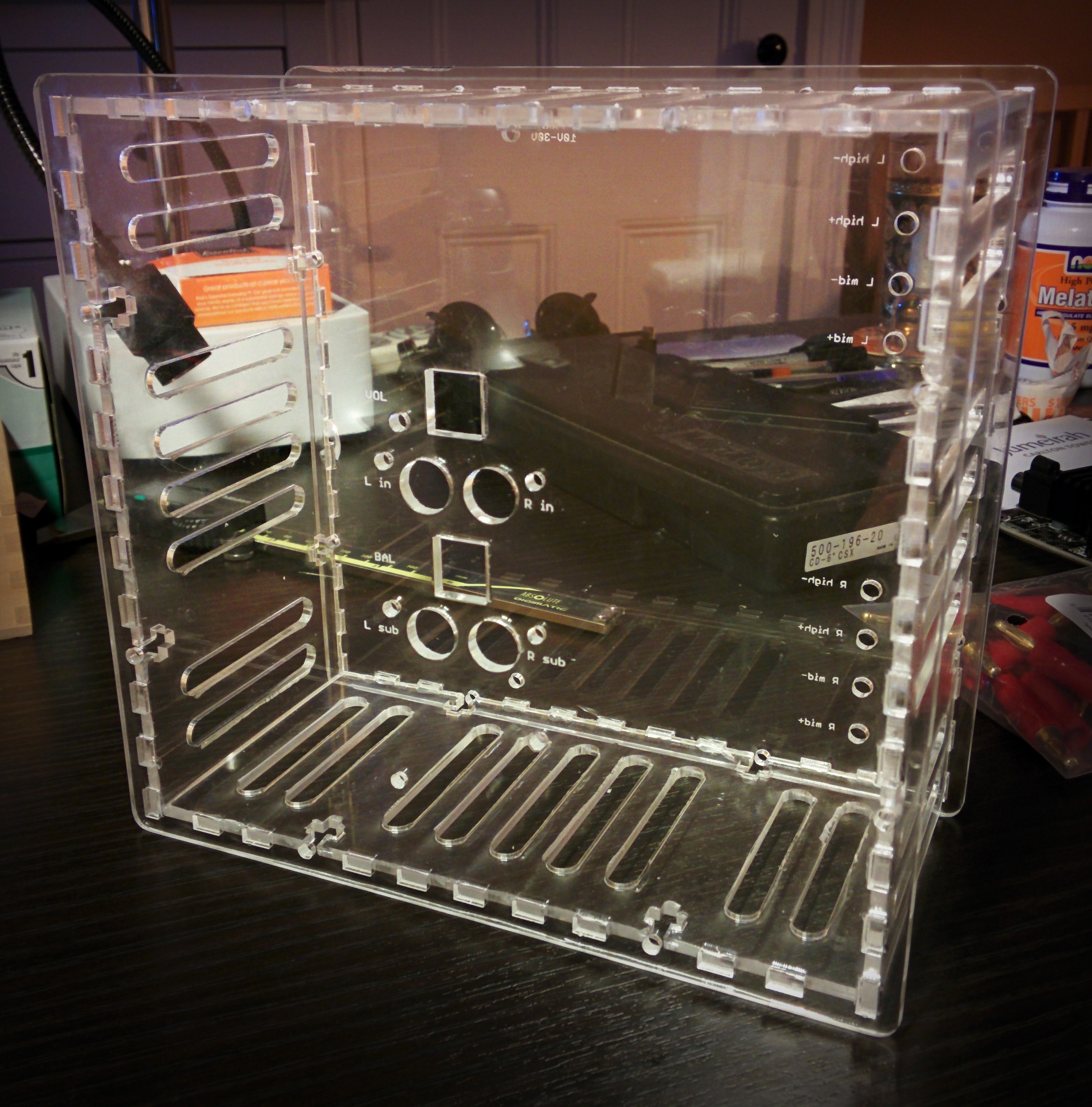 (initial fit.)
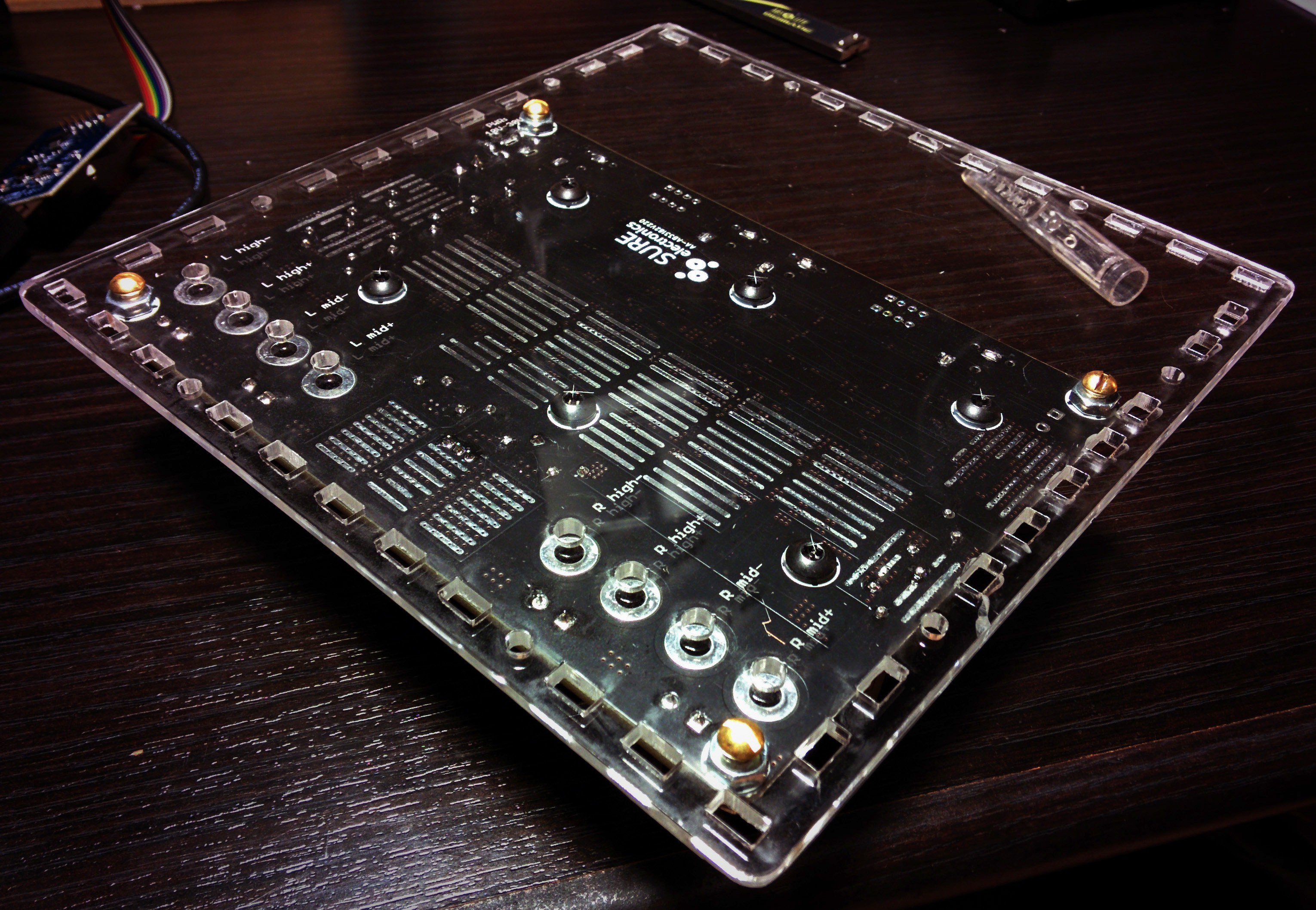 (those screws are too high. i'll have to cut holes around them.)
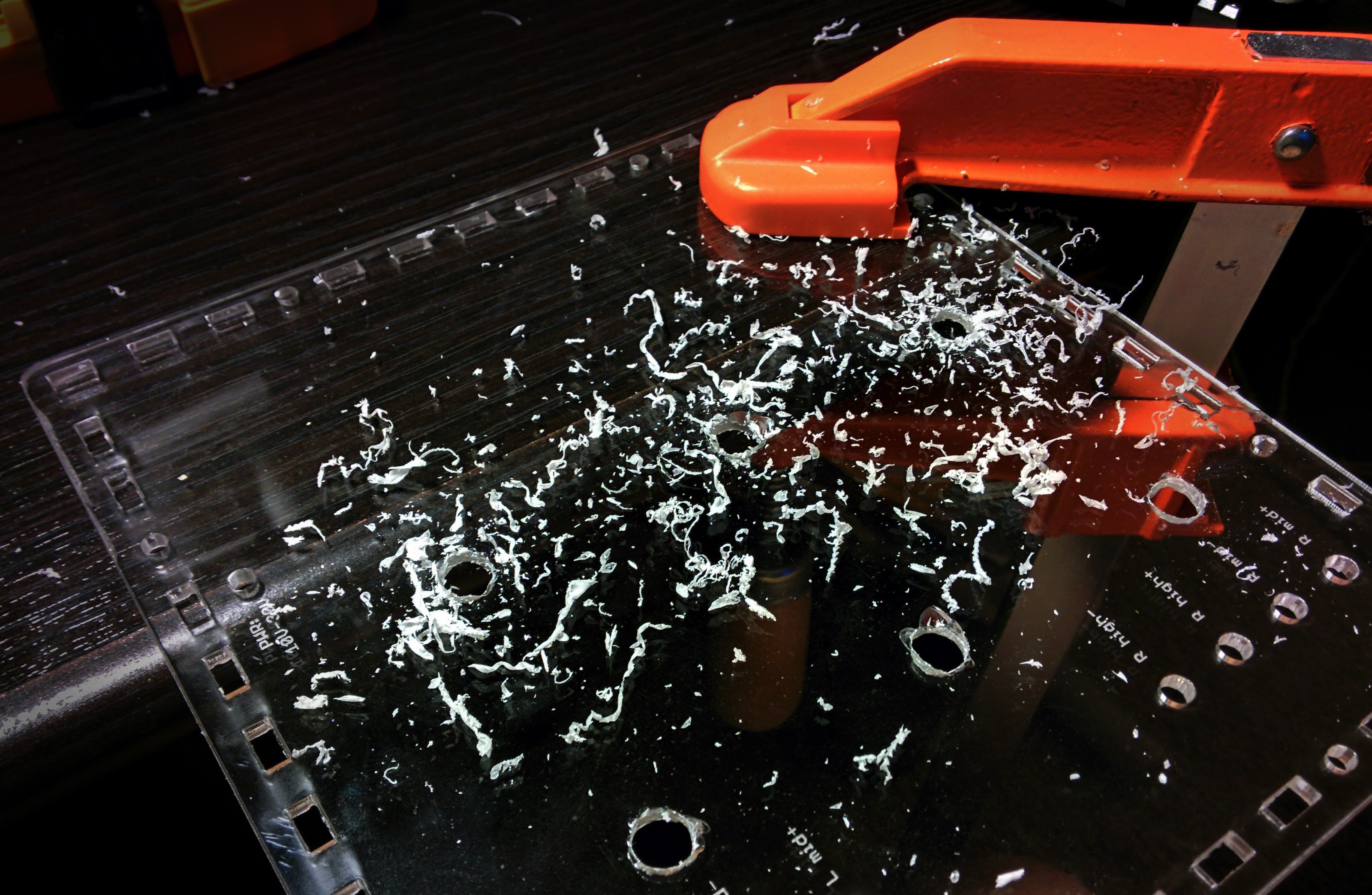 (all precision projects must ebb to barbarism.)
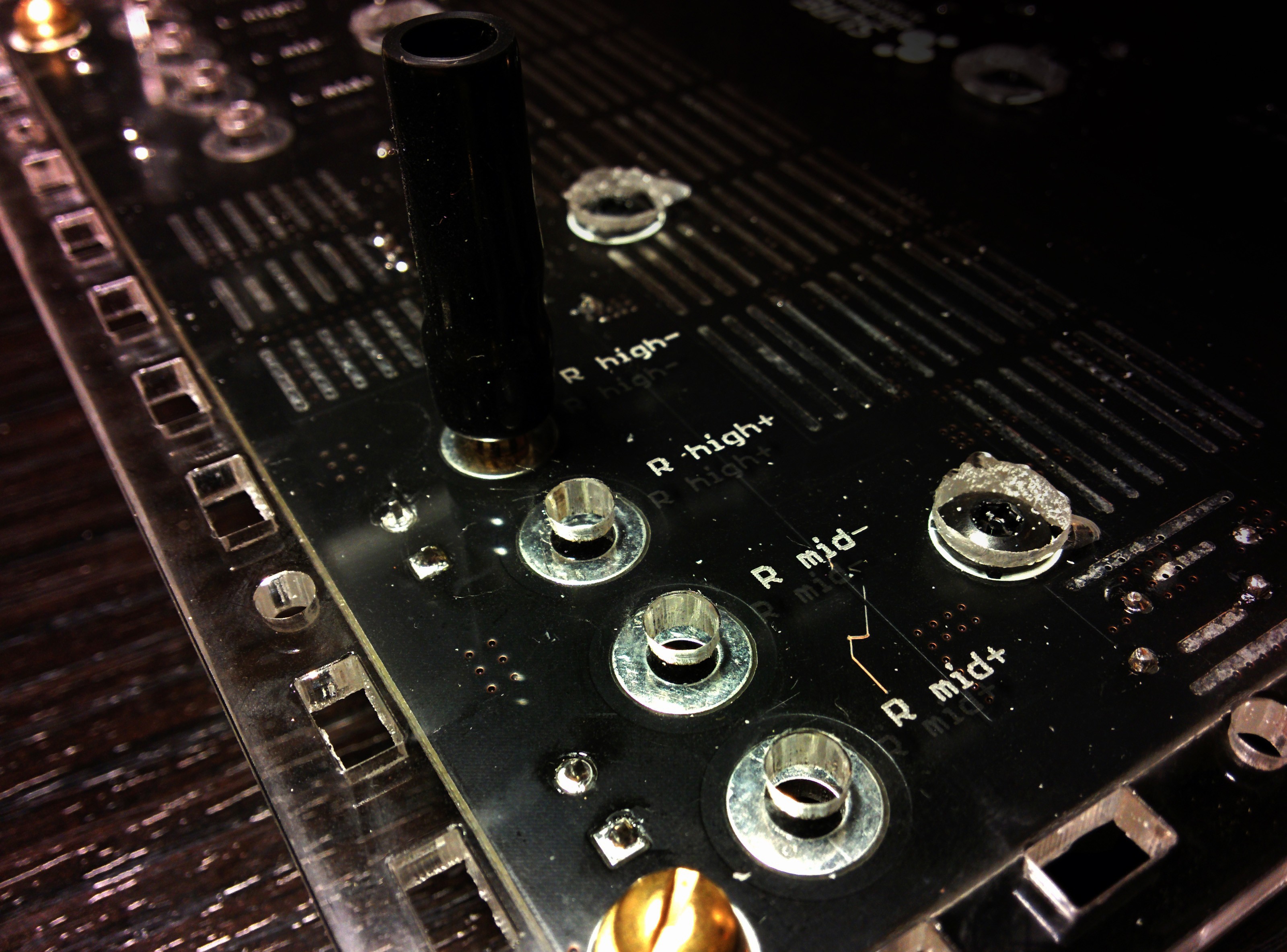 (banana jacks fit with a 4.8mm shoulder.)
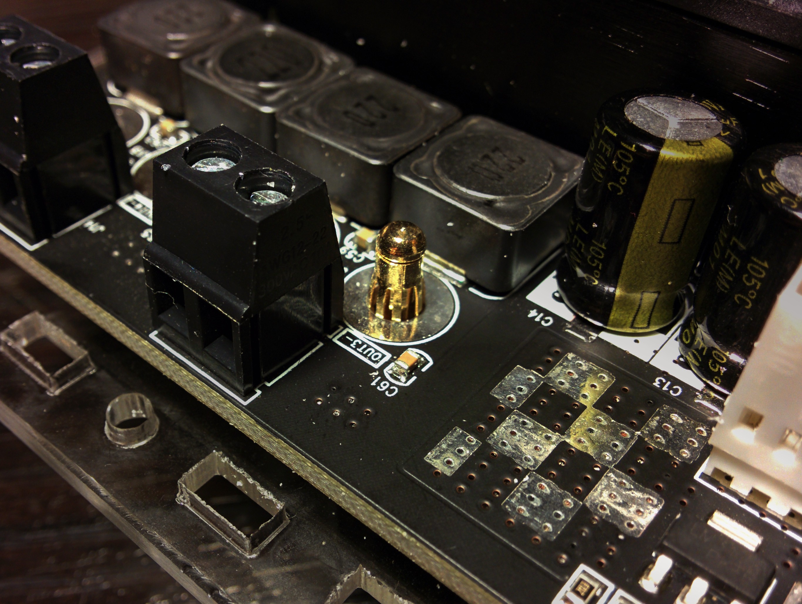 (the contact bulge meets the via.)
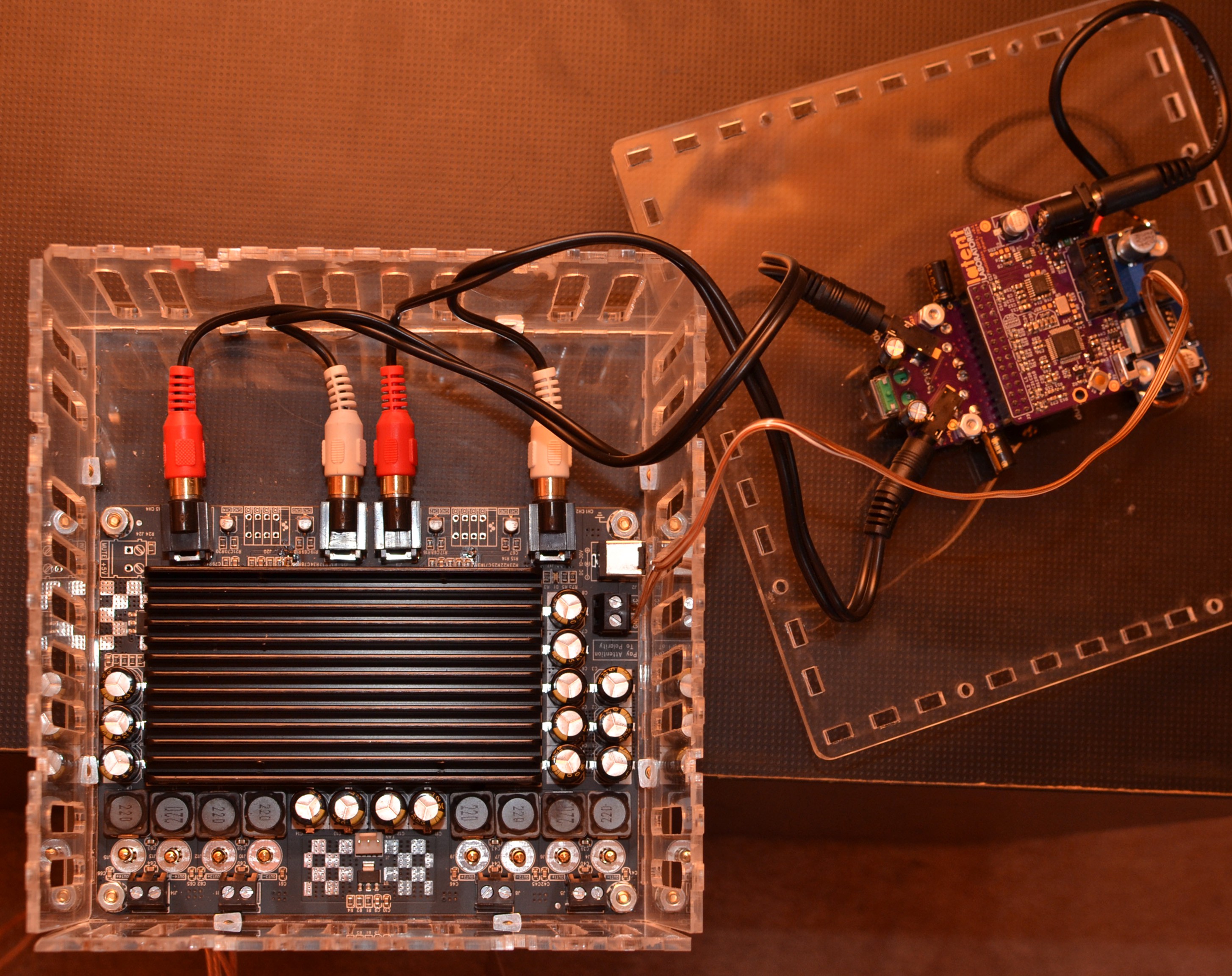 (amplifier, DSP and buck converter.)
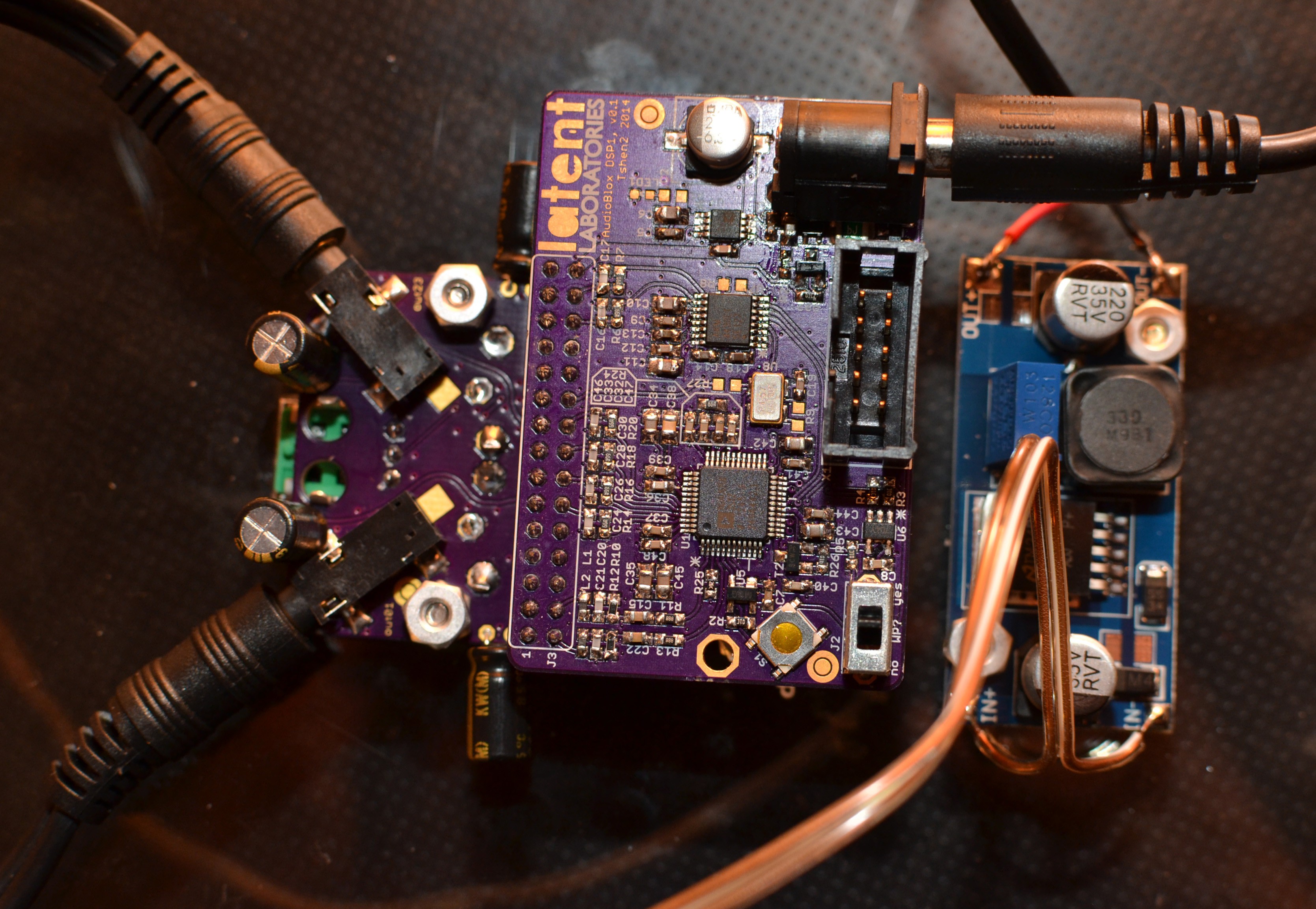 (DSP in detail.)
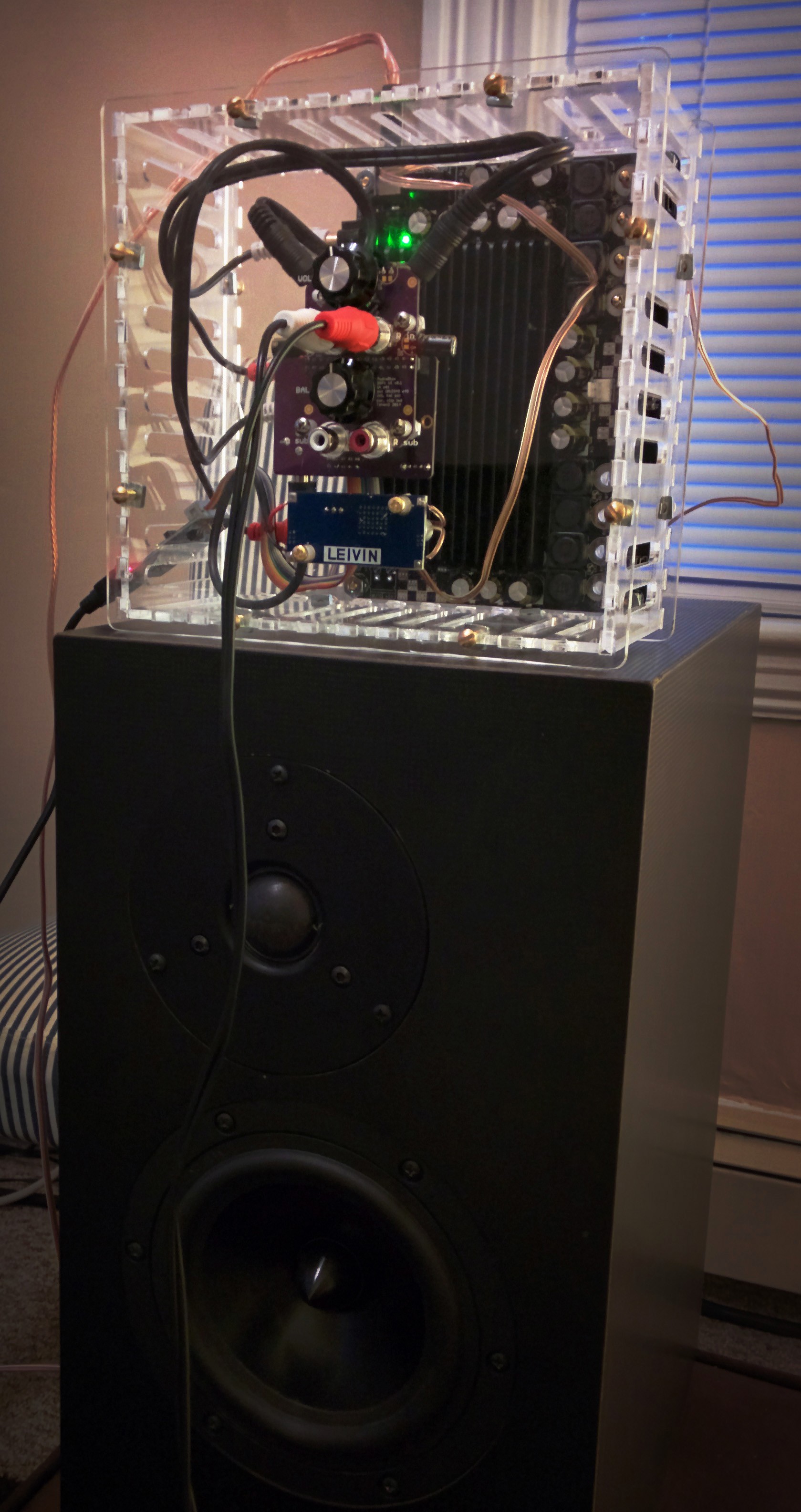 (ready for testing.)
next update, i will describe my acoustic measurements and DSP programming.
Tshen2 2014
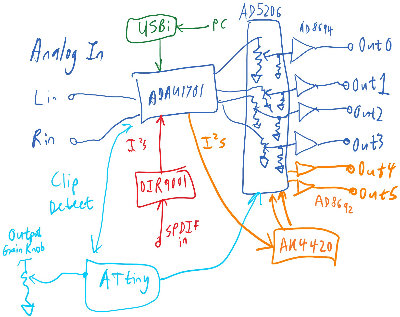 (image: DSP architecture, version 1)
here are the goals i set for the DSP:
the heart of my DSP is Analog Device's ADAU1701. it is an amazing piece of work. two 24-bit ADCs and four 24-bit DACs. integrated 50MHz DSP core. self-boot capability. auxiliary 8-bit ADC to read potentiometers.
coming from a place of analog skepticism, i expected it to sound awful. i planned to use digipots on the outputs to do volume control in analog, and avoid digital attenuation. i threw in a microcontroller (ATtiny) for clip-detect and to adjust the digipots. i added output amplifiers.
then i actually listened to the evaluation board and it sounded fine. the digipots and output amplifiers were completely extraneous. clip-detect could be built into the DSP itself - i could leave out the microcontroller too. this led to a much simplified version 2:
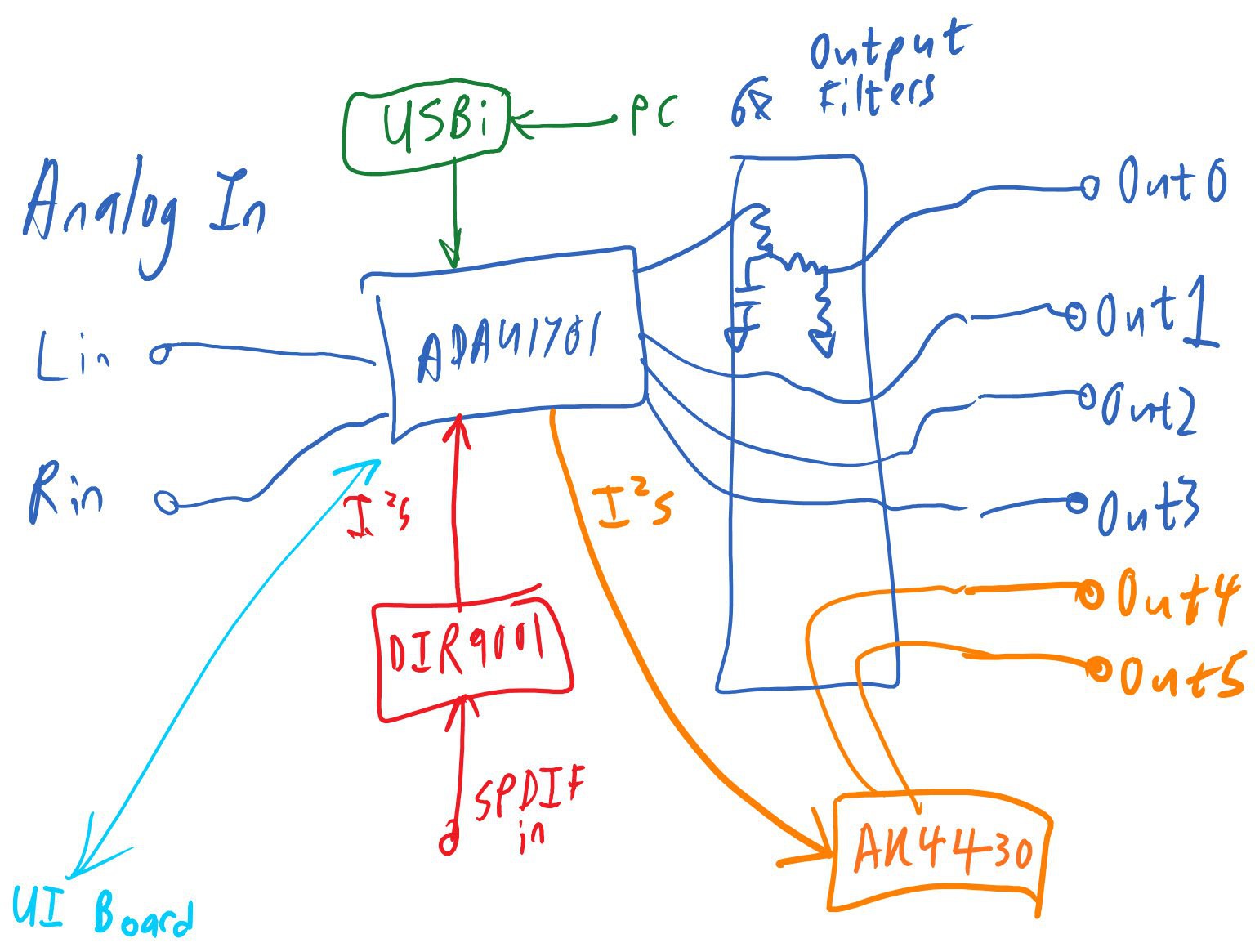
(image: DSP architecture, version 2)
this includes:
after more listening, i decided the SPDIF input was also extraneous. i would include the hooks to add it later. it could live on the modular user interface, and connect through a header.
these changes led to version 3:
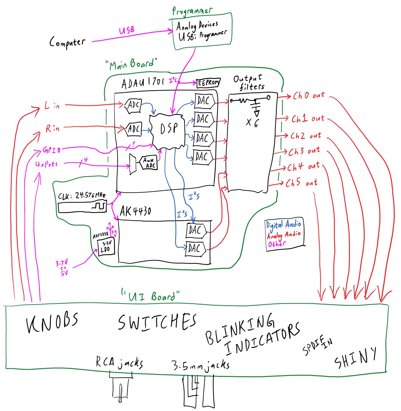
(image: DSP architecture, version 3)
why a 24.576MHz clock? the AK4430 delivers maximum THD+N if your master clock is at least 512*(sample rate). at a 48kHz sample rate, that's a minimum clock of 24.576MHz. this relationship exists because the AK4430 uses a switch-cap output filter. like all switch-cap filters, its corner frequency is affected by the clock frequency.
why the AK4430 at all? it's good enough, and quite cheap, and runs at 3.3V.
now let's calculate our power requirements:

looks like our worst-case current draw is about 200mA. what about power supply noise?
ADAU1701 power supply noise requirements:
AK4430 power supply noise requirements:
the ADP3335 LDO has excellent load regulation, 500mA maximum output current and a peak voltage noise of under 0.3 mVpp. it will do fine.
i'll also throw on a 30-pin header to connect the Main Board and the UI Board.
time to bang it out!
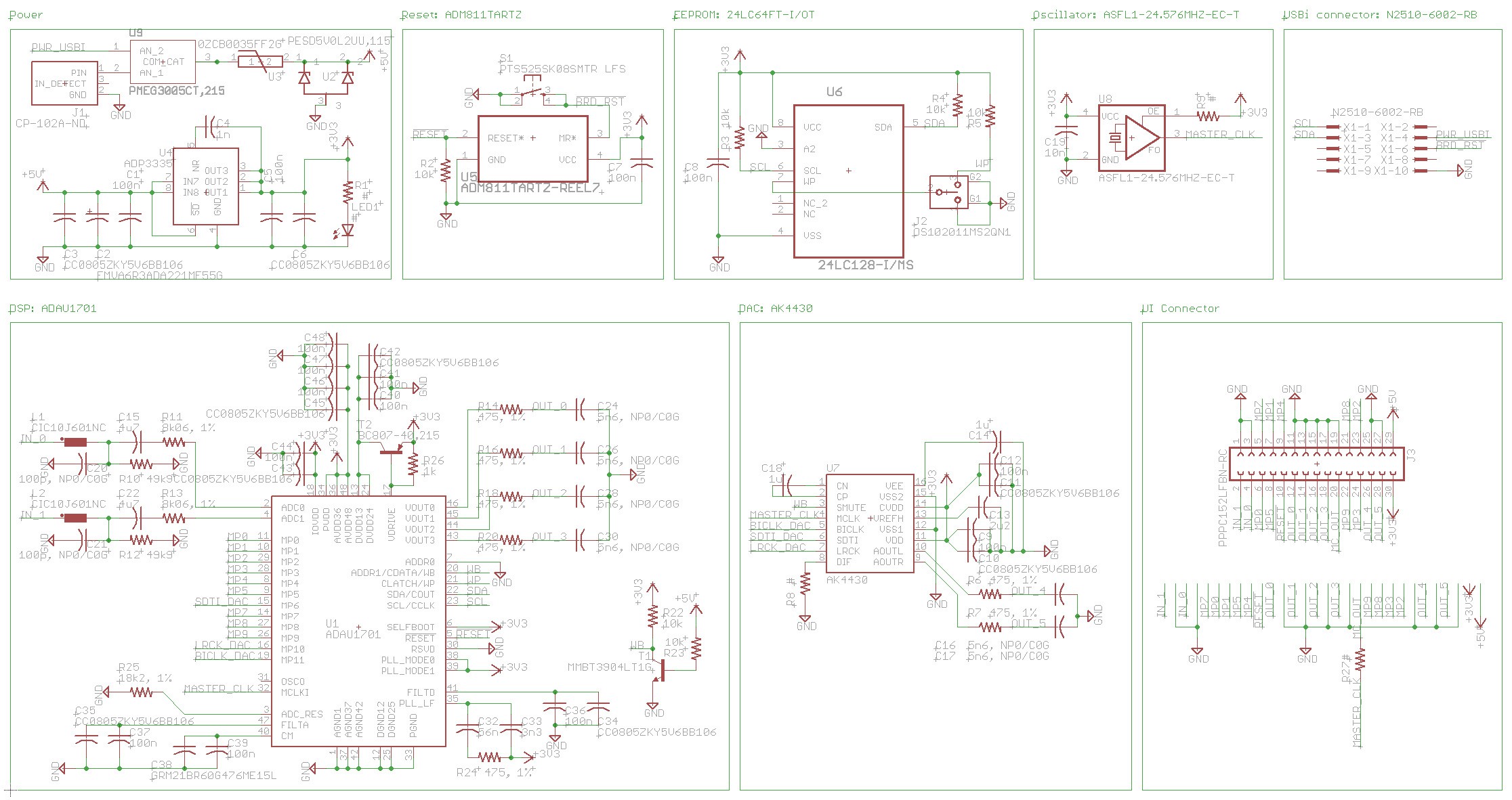
(a picture is worth a hundred hours)
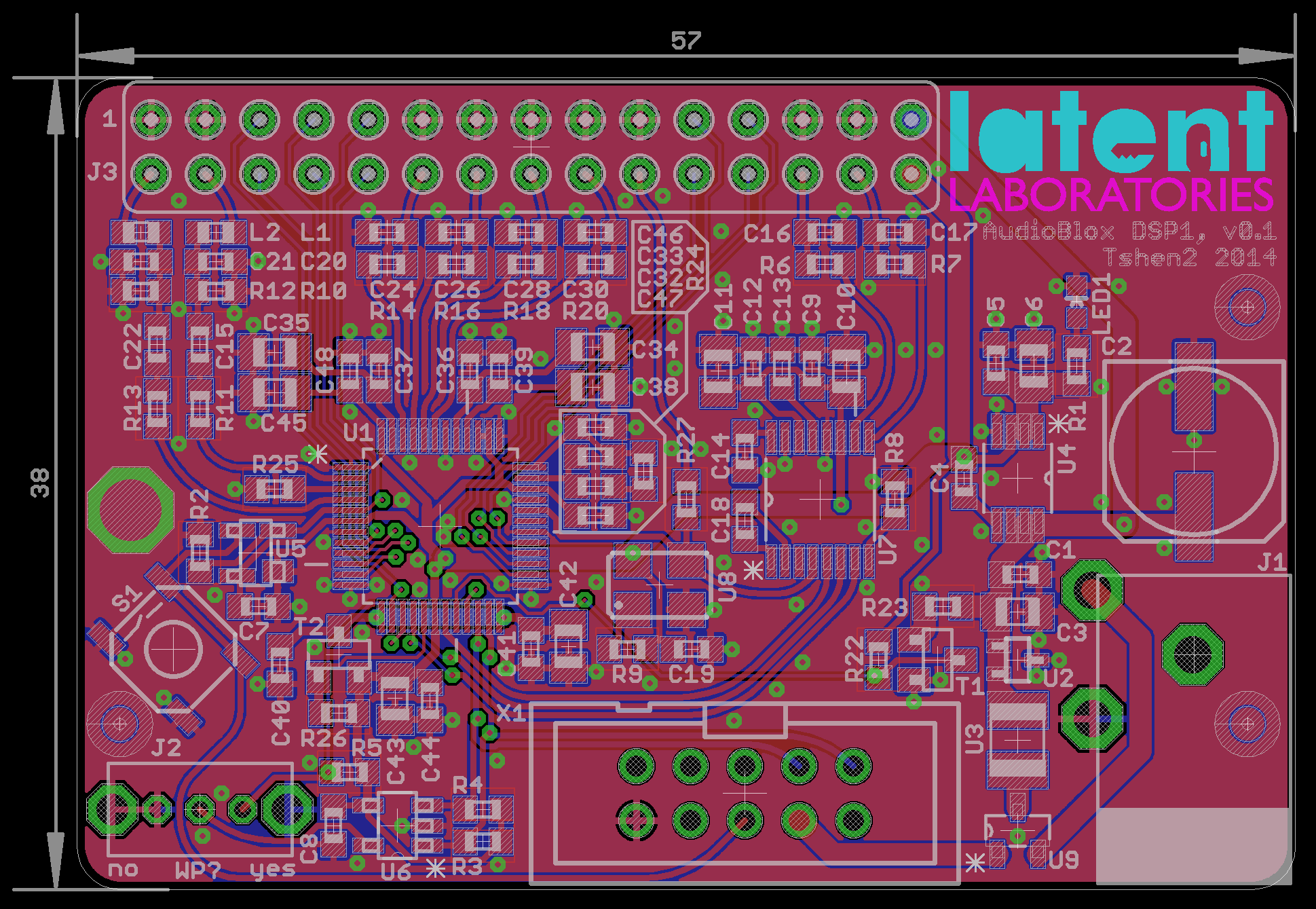 (two pictures is worth 200 hours)
OSHpark time!
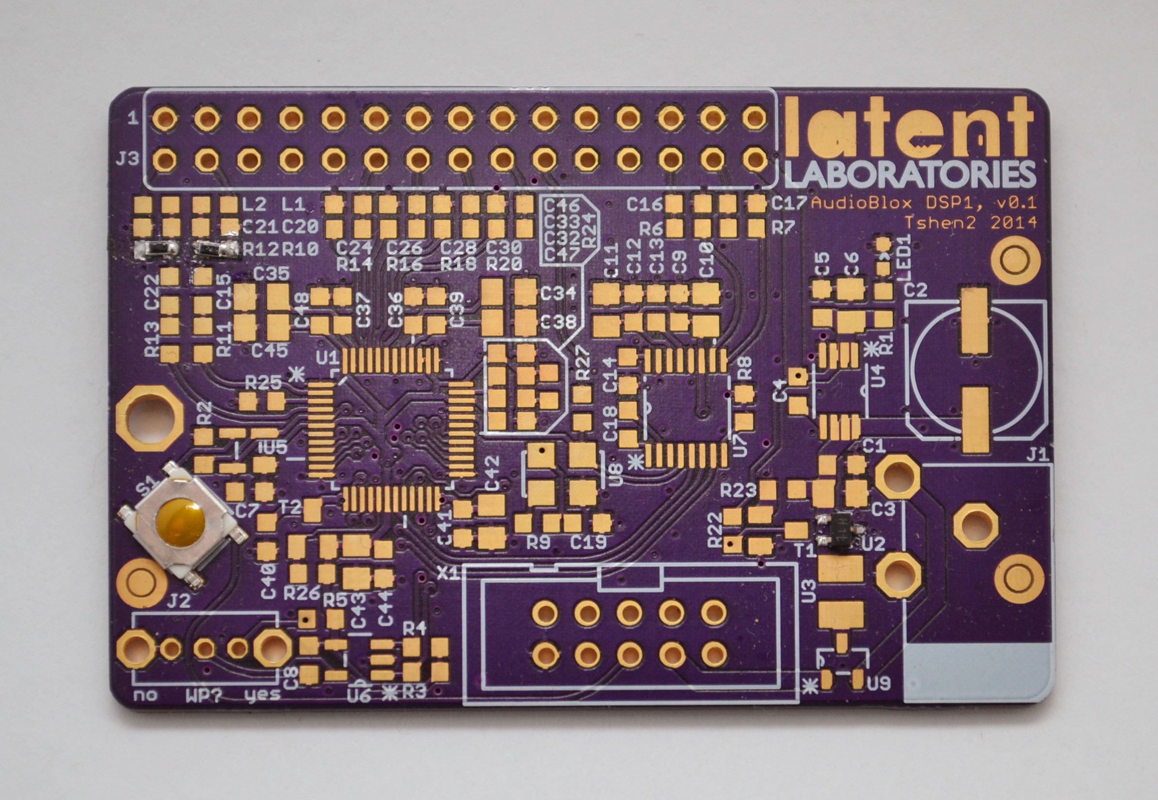
(did it work? yes.)
next update, i will describe the user interface and lasercut chassis.
Tshen2 2014
Create an account to leave a comment. Already have an account? Log In.
Dude this project is amazing, not only for the quality of the end-build that totally succeded in its final purpose, but also for the crazy amount of detailed project-specific and complementary information reported in the logs.
You, sir, deserve a cookie.
freedsp actually has a design one can build in the $10 to $15 dollar range that lets you make your own programmer.
Become a member to follow this project and never miss any updates
This project is so awesome. I'm going to have to build one myself!