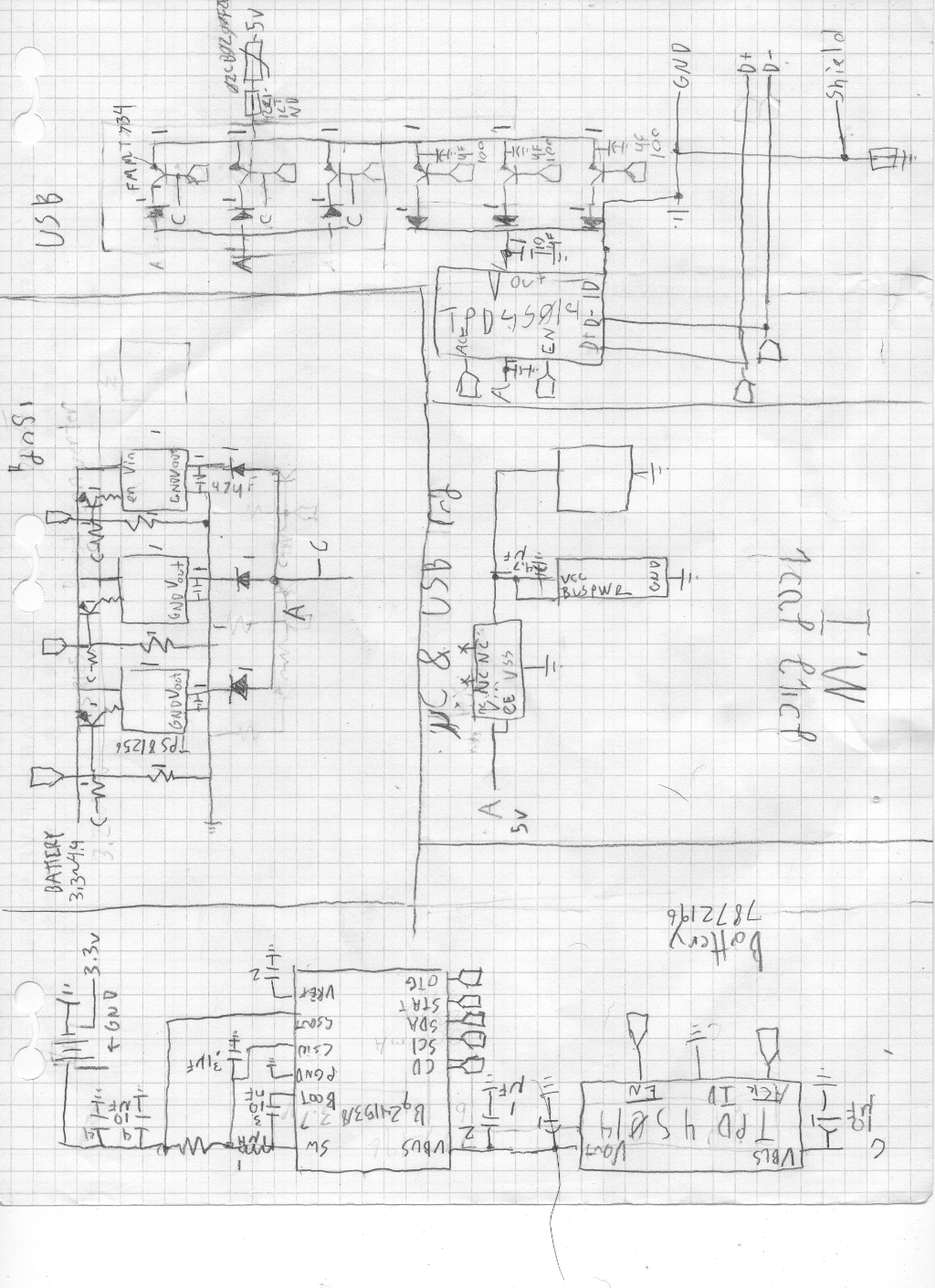
It's not pretty by most senses of the word, but it's almost ready to get moved into KiCAD for a proper layout. This isn't everything that I wanted, but it's what I needed to make this power system function* enough for a test. After about 5 iterations this week, I have come to this design. All the tags on the page go to the Micro Controller. The USB should support two way power systems, and there is plenty of battery power for the system without the exterior batteries. I have put up safety guards for the power and data lines, set up the shield and made the boost converter rail diagram for the BABP (Big alternative battery pack).
I have added some design rules to the tablet.
- All exterior batteries must boost convert to the 5v rail. This saves a lot of trouble balancing.
- You have 1.5A ~ 2A coming down the line at any moment... if you don't want your stuff to break limit the amount of current it takes... My stuff will survive the ordeal.
- the SPI/I2C lines belong to the video, bridge board, and main board.
Some interesting things cropped up as I added control transistors to stop and allow current flow. I didn't notice it until I began writing it, but I could increase efficiency by attaching sensors to the boost converters, and turn them on and off by how much current is going though them at any moment. Too low it gets turned off. But, that will have to be added in a later edition of the bridge board. Also, all the diodes that you see are to represent ideal diode circuits. I haven't picked out which one I am going with yet.
As for now I can label the unlabeled components, test the design (if ltspice has all the components. Otherwise I will just have to test small fractions of the circuit), put it on a board schematic/gerber file, and prep it to be ordered from OSH Parks.
 Krinkleneck
Discussions
Become a Hackaday.io Member
Create an account to leave a comment. Already have an account? Log In.