-
Putting the project on hold
12/15/2015 at 19:20 • 0 commentsI already had little time to work on this project while in high school, so now that I'm in college, I'll have to put this project to rest. Perhaps I'll come back to it a few years down the road.
-
Personal issues
09/29/2014 at 06:49 • 0 commentsAs you might have noticed, I have not worked a whole lot on this project since the last checkpoint. Unfortunately, I was sick for more than a week and have lots of schoolwork to deal with. Hopefully, I can work on the project much more in the next few weeks.
-
My conversation with a real astrophysicist
09/29/2014 at 06:47 • 0 commentsI recently spoke to a friends's father whose research and dissertation was exactly on what I am doing in this project: detecting cosmic rays through air showers. He said that this should theoretically work, but told me that 2 things need to happen: first, I need to increase my detector area. This can be done by adding lots of metal above my PIN diodes so that particles cascaded and multiply, without having to use too many diode. Second, I need to increase my timing resolution by one order of magnitude. This should not be difficult as long as I use pulse integration, as explained in an earlier project log.
-
What to detect
08/31/2014 at 02:33 • 1 commentI've been doing a bit of reading on other solid state detectors and have decided that it's a great idea to detect muons rather than gamma rays. Secondary showers consist mainly of electrons, photons, and muons. Unlike photons, muons are easily able to pass through thick metal shielding. This means I can detect only muons by adding thick metal around the pin diode. (I was going to add some shielding anyway to prevent electromagnetic interference. I realize now that this simultaneously decreases gamma ray sensitivity in a somewhat unpredictable way.) The benefit of detecting muons rather than gamma rays is that the node will detect less terrestrial background radiation, which is important if I intend for the node to be used in somewhat populated areas.
At this point I'm not sure what kind of material or thickness is needed for the shield, nor am I totally positive that detecting only muons is the right way to go. Thankfully, my detector design is flexible enough that I can continue working on the electronics and software while simultaneously working on the particle physics aspect.
Coincidence detection might also be something to look into. This is where two PIN diodes (or hopefully array of diode) have shielding in between them, and a circuit is used to record only events where the top detector get a pulse a certain amount of time before the bottom detector. This should reduce terrestrial radiation interference even more.
-
Hooray!
08/25/2014 at 20:25 • 0 commentsI made it to the top 50! I just need to make sure I keep working on and documenting this project.
-
Future Goals
08/21/2014 at 04:47 • 0 commentsRight now I’m assembling a first prototype of the detector node. I’ve determined a few things which need to get done in order to make sure the device will work how I’d like it to.
1. Optimize timing accuracy
I’d first like to see how I can modify the GPS settings to get the most accurate clock pulses. I also want to experiment to find the best algorithm for utilizing the GPS pulses. This means measuring how many Arduino clock pulses it takes for a single GPS pulse over time, and seeing if averaging is necessary. This also means making more intelligent code which accommodates for the timer ticking while each byte is recorded. (I haven't thought through that last part entirely, but I may not have to accommodate for this delay as long as it is consistent.)
2. Optimize protocol for server communication
I need to find a balance between minimal processing by the Arduino and minimal transmission size. I also need to determine if the detector node should immediately send data, or rather accumulate data on the SD card and then send it to the server.
3. Increase detector sensitivity
I realize now that a single pin diode probably isn’t enough. This means I need an array of pin diodes. I need to determine which pin diode on the market is most worth its cost. I also need to determine which amplification circuits and ICs work the best.
4. Determine calibration procedure
All nodes need to have the same sensitivity and delay; this means calibration is important. I need to determine where in the circuit pots or adjustable caps are required, and what accuracy each discreet component needs to be. Then, I need to find a good way to ensure that the nodes can be calibrated without any expensive test equipment. One idea I have is to use readily available americium from smoke detectors to calibrate sensitivity.
-
Project Video
08/19/2014 at 07:16 • 0 commentsI took the creative approach.
-
Detecting button presses
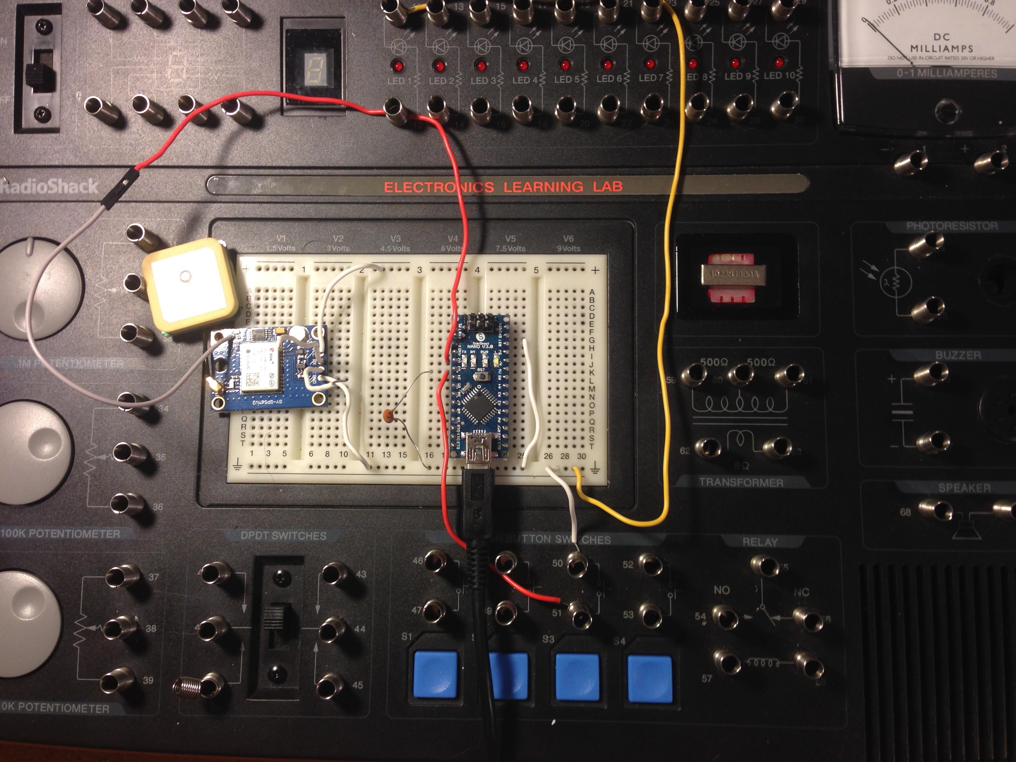
08/15/2014 at 01:59 • 0 commentsI modified the Arduino program to output the raw time for both of its interrupt pins. In lieu of a working gamma detector, (as the op amps haven't arrived yet,) I used a button press to simulate a pulse.
![]()
I added a small parallel capacitor to the button in order to remove any contact bounce. I also wrote some javascript to compute the length of time between the button press and last GPS pulse.
Next, I need to have the Arduino read the serial data from the GPS, which includes not only location but also time of the last sent pulse. Considering how easy it is to implement timing measurement, I think I'll try to use one microprocessor rather than two. If I can get everything, including networking, working on a single Arduino, that would reduce a lot of the cost I originally estimated.
-
Current state as of me first posting the project online
08/13/2014 at 23:45 • 0 commentsI've been working on the project for about a month now. I decided to post it to hackaday only recently, so I've got a lot of stuff to go over.
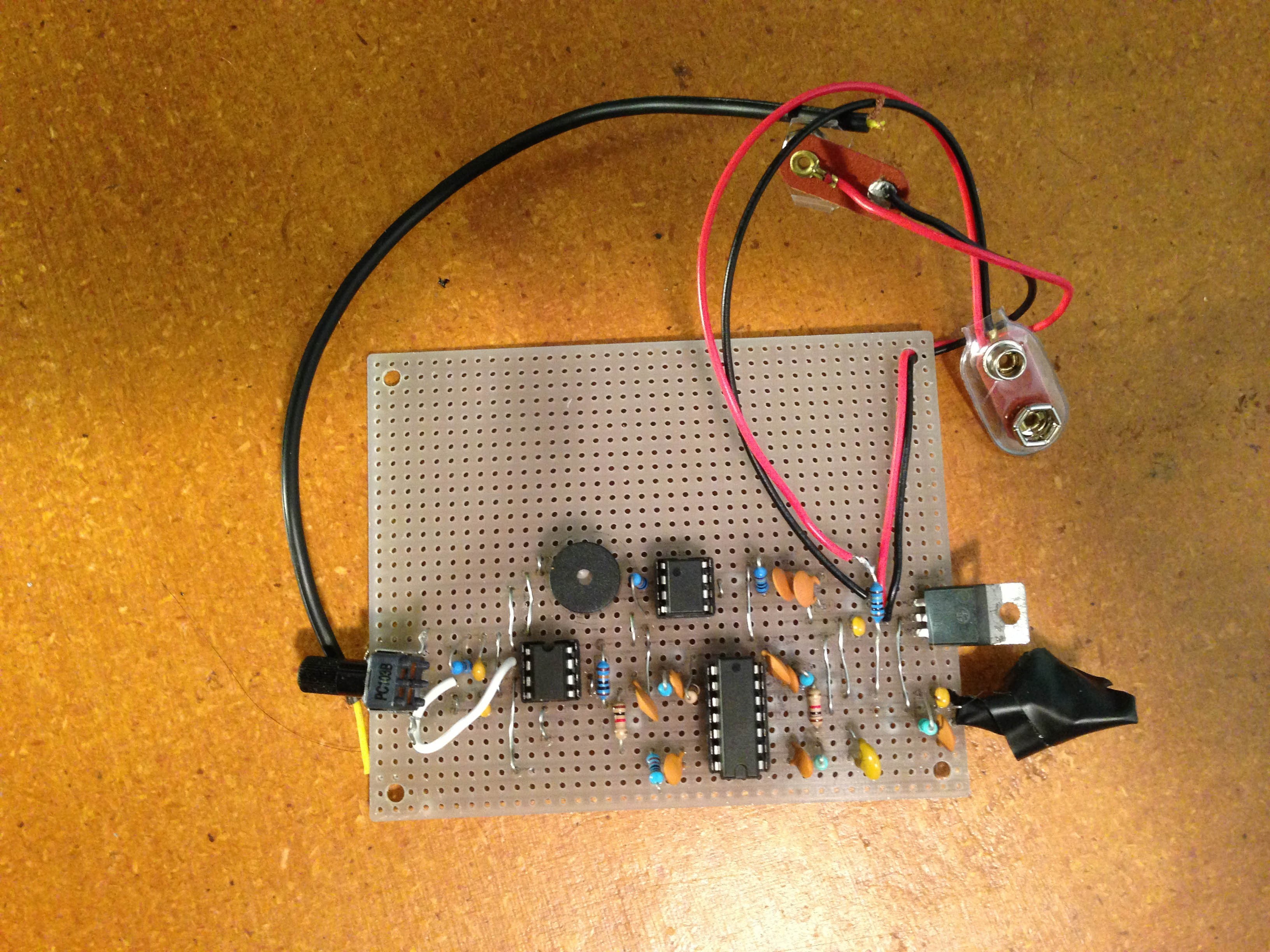
The first thing I did was build just a gamma ray detector. The output is hooked up to the trigger of a 555, which is also connected to a buzzer, so that I get a beep every time a gamma ray is detected. I accidentally bought an op amp with too high of an input bias current, so the detector does not work correctly right now. However, I'm ordering a new op amp which should get the detector working and beeping.
![]()
The PIN diode is inside the electrical tape below the voltage regulator. The white bodge wire is there because I accidentally flipped the inputs on the comparator.
Next, I experimented a bit with peak detector circuits. I realize now that the circuit from EEVblog #590 is probably not fast enough. I'll work more on the peak detector once I get the gamma detector working.
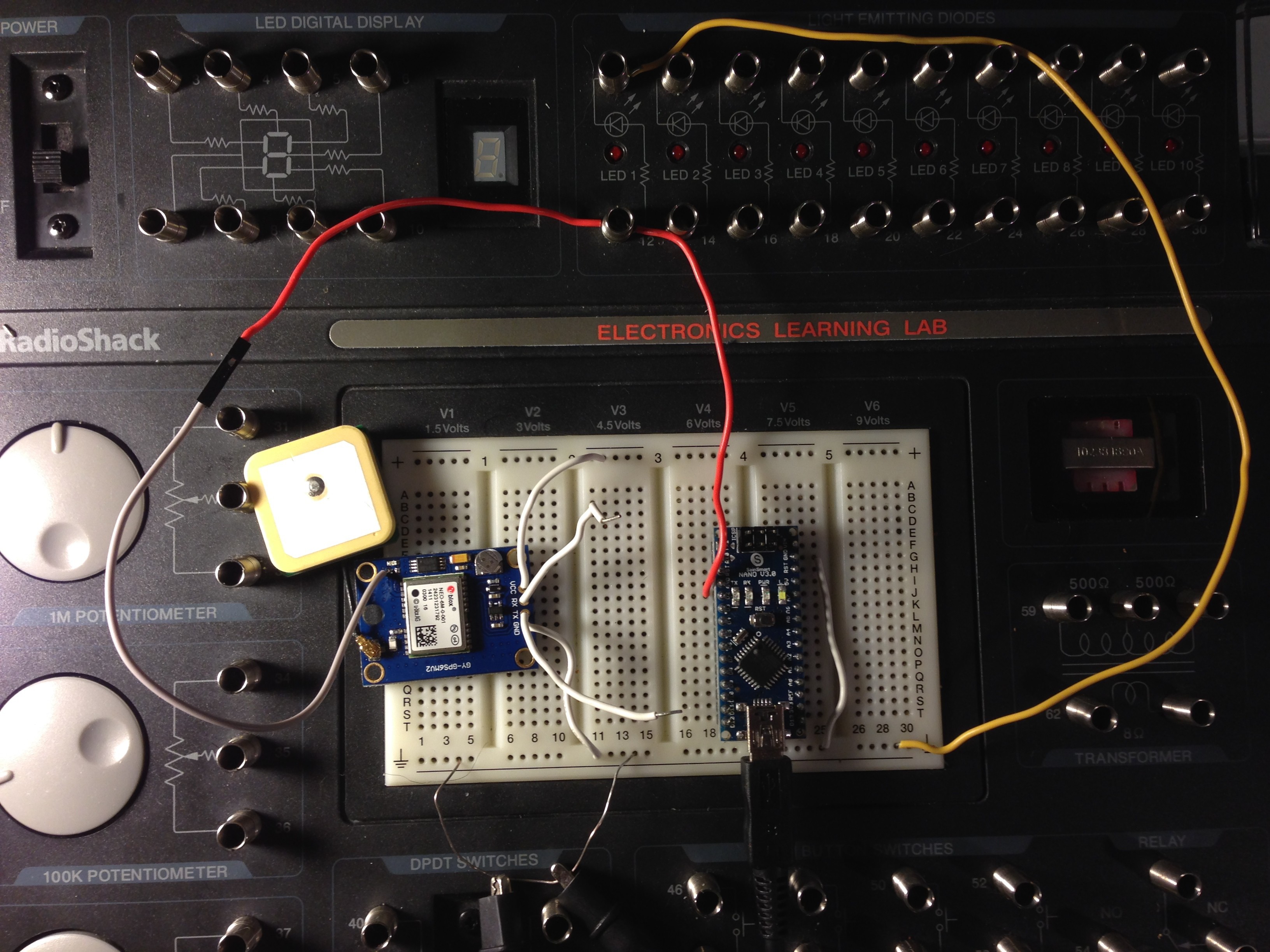
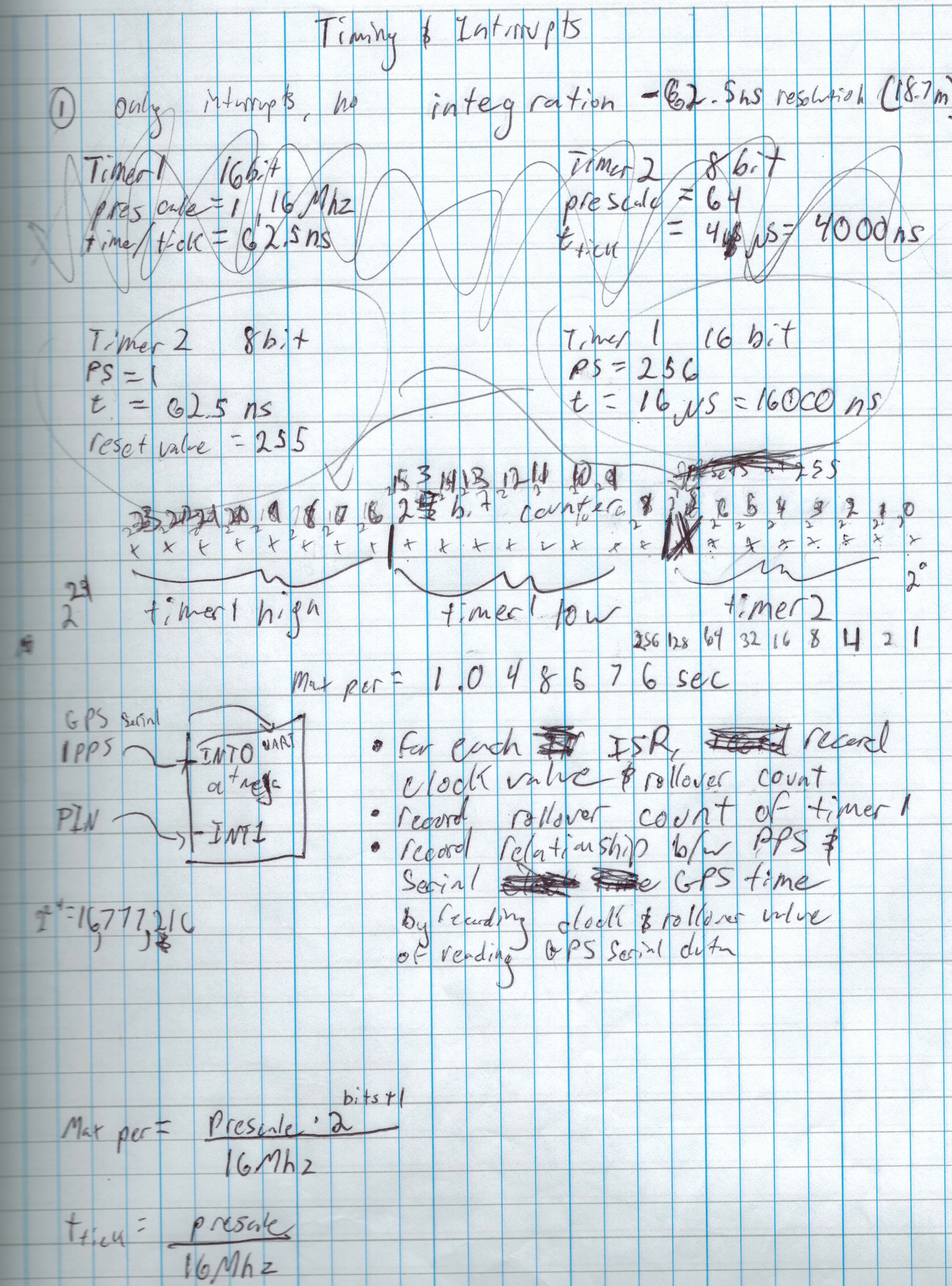
Finally, I bought a GPS module and arduino and got the arduino to detect the GPS's pulses to within 62.5 nanoseconds. I did this by setting up two timers and an interrupt. One timer ticks up when the other overflows. When the arduino detects a rising edge, it reads the values of the two timers, in addition to the count of the slower timer overflowing. You can see the code I used here.
![]()
I'm using a NEO 6M GPS module with an Arduino micro clone.
![]()
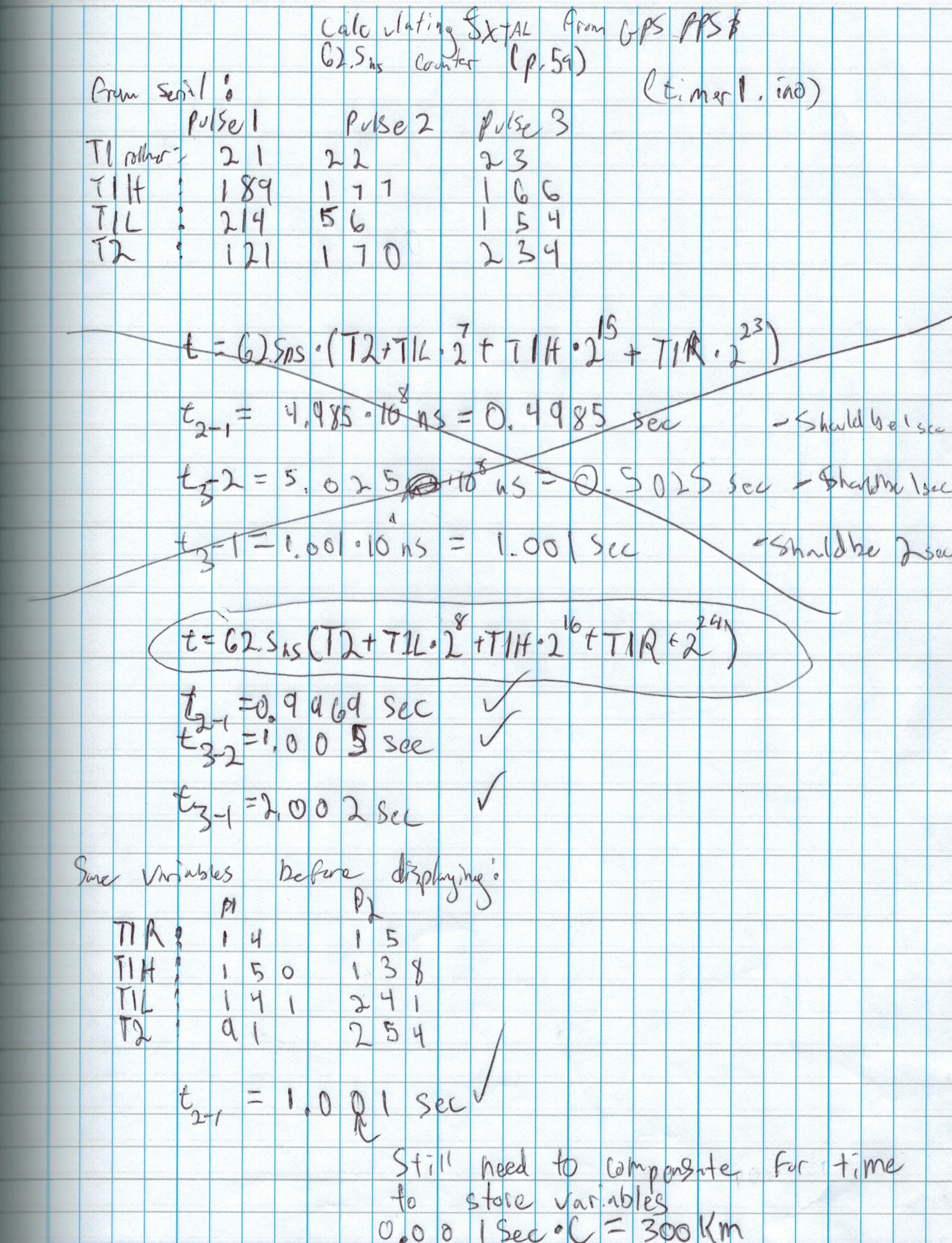
Here are my notes for how to measure pulses to within a single 62.5 nanoseconds. I use both timer1 and timer2.
![]()
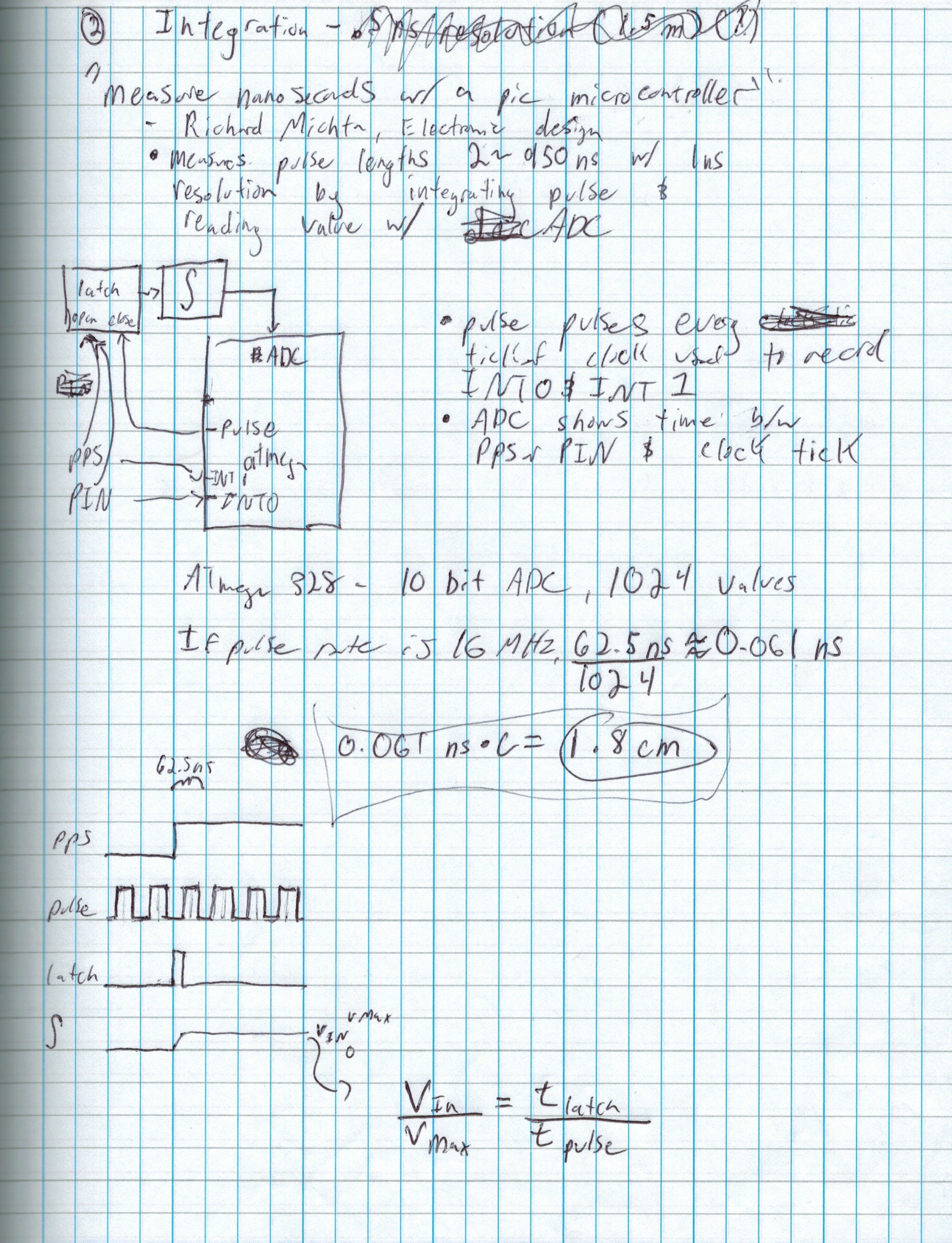
Here is how I can measure to within 0.061ns. I can do this by integrating a new pulse the length of time between the pulse I'm measuring and the next tick of the arduino's crystal oscillator. Although I could try to implement this, it's a lot of extra work, and the GPS's pulses are only accurate to around 30 or 60ns anyway.
![]()
Here's proof that the timing works. My math got a bit messed up at first so that the results were around half of what they should be, but then I corrected my formula. You can see that the GPS and arduino's time are slightly different, which is what is expected.
Low-Cost Solid-State Cosmic Ray Observatory
Multiple nodes detect photons to within nanoseconds to analyze cosmic ray air showers and help solve the Greisen-Zatsepin-Kuzmin paradox.
 aelias36