-
Software
08/19/2014 at 23:23 • 0 commentsMy goal is to make the wireless wires without an embedded processor. My reasoning behind this is to keep cost and complexity down - plus who wants to deal with upgrading firmware on these.
One of my main motivations for making this device, though, is to use it in conjunction with my smart phone. I can think of a lot of situations where my phone will be the receiver/transmitter and the other end will be some sort of device that employs a wireless wire to communicate with me (it's only communicating one bit - anything more and I'd move to Bluetooth or WiFi, of course).
To that end I'm planning on writing an open source android library that can be used to both detect specified tones from the microphone, and emit them from the speakers.
In the future desktop compatible libraries may also be considered.
-
Interference
08/19/2014 at 23:15 • 0 commentsA question was posted on how interference will be handled. It is a good question. When watching the video I posted it looks like my voice is causing interference with the (almost) ultrasonic tone. I think what might be happening in the video is the microphone amplifier that I am using in the proof of concept (MAX9814) has automatic gain control which is amplifying my voice and attenuating other frequencies - including my 18k tone.
I believe that moving to more appropriate hardware for these ultrasonic tones will alleviate this problem.
Another problem to worry about is what happens when the tone that the receiver is listening for is being generated by something else in the vicinity. This could be handled by providing access to a trim pot that would allow users to select a different frequency. The problem, though, is that the transmitter would also need to be adjusted. This would get tedious very quickly.
A solution that I am currently leaning towards is having the wireless wires require/emit two different ultrasonic frequencies. Both need to be detected by a receiver in order to turn on, and when a transmitter is set high both will be generated.
-
Voltage Regulator
08/19/2014 at 03:32 • 0 comments![]()
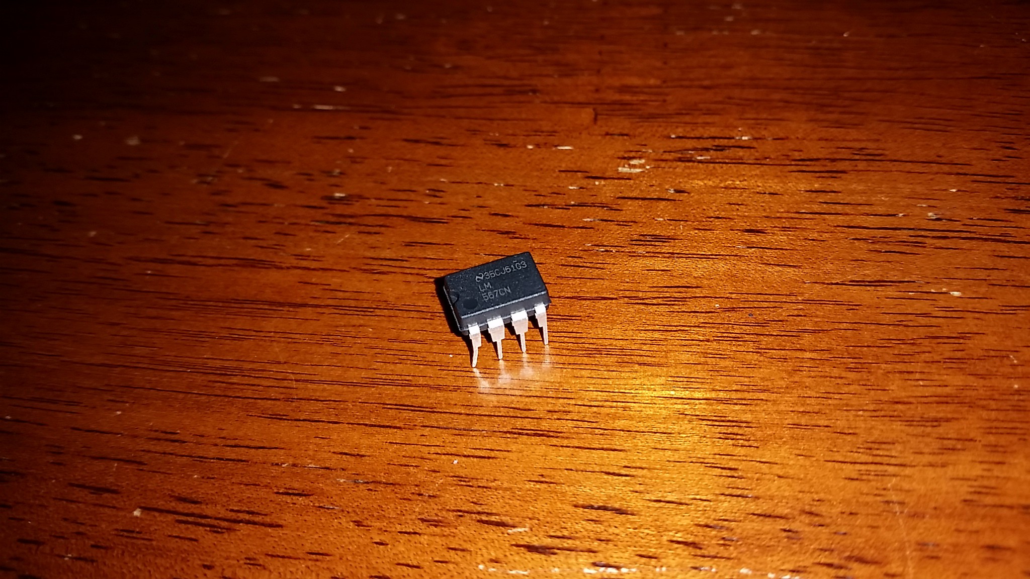
The LM567 tone decoder, which I'm considering using in this project is a Voltage Controlled Oscillator (VCO). As such, to have a paired transmitter and receiver you either have to have a pot to tune each side, or regulate the supply voltage.
For ease of use I want to avoid having to tune the circuits. I also don't want to limit applications by requiring both the receiving device and transmitting device to be running at the same voltage. So I'm planning on using a voltage regulator that can supply all of the wireless wires with a fixed voltage, regardless of the device they are being used in.
-
Transmitter Details
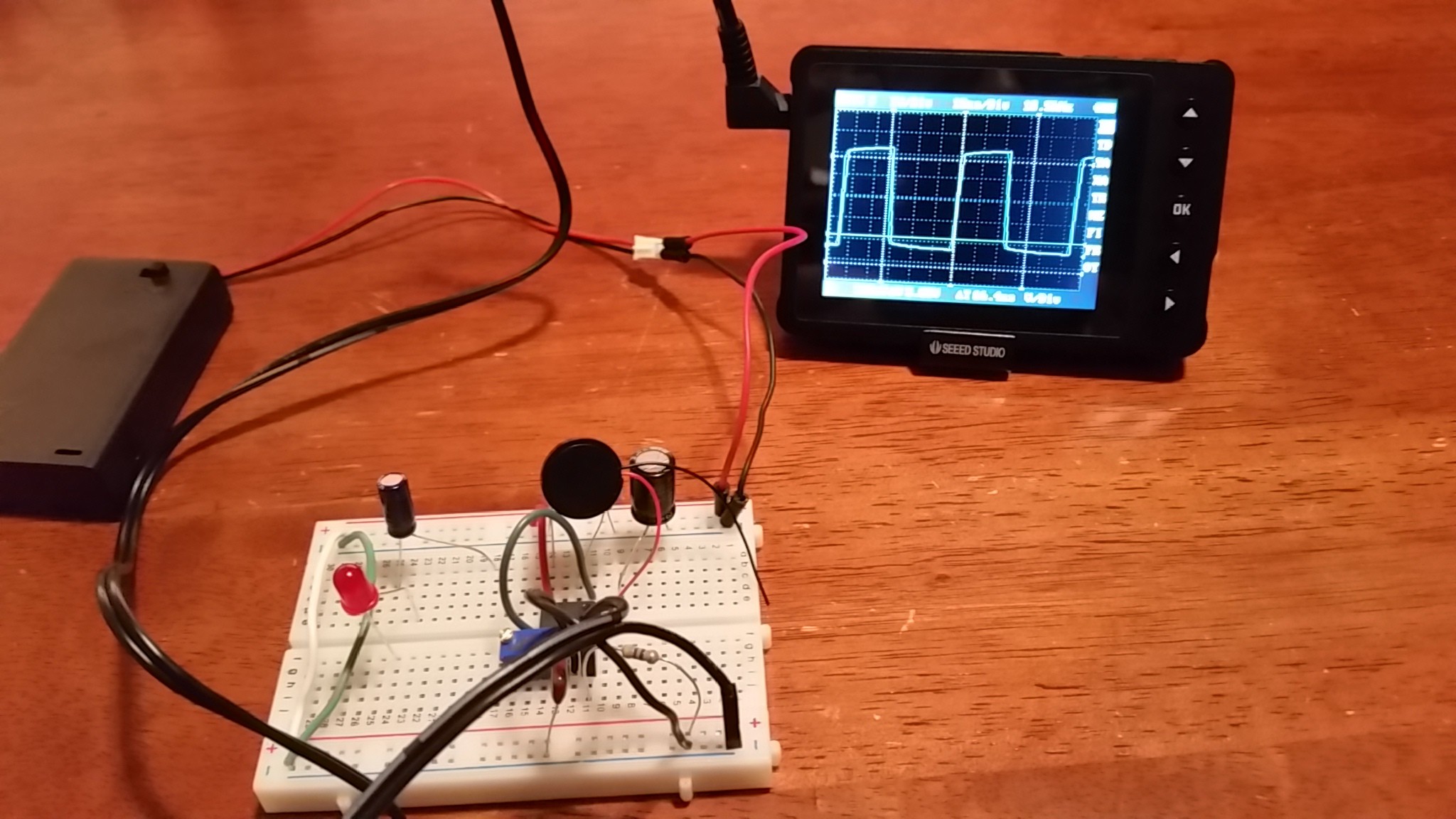
08/17/2014 at 03:02 • 0 commentsI was generating some lower frequencies with the transmitter while looking at the spectrum analyzer app and noticed that there was often a harmonic frequency generated.
This makes sense because the LM567, when configured as an oscillator, makes a square wave. I verified this with an oscilloscope.
![]()
In later version I will see if I can convert that square wave to a sine wave.
-
Borrowed Oscilloscope
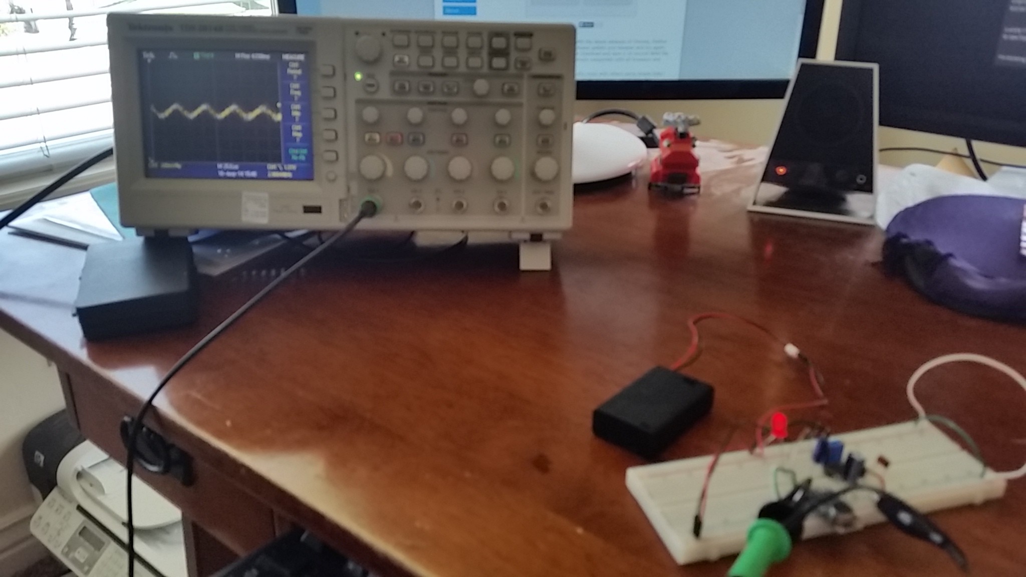
08/16/2014 at 21:36 • 0 commentsI borrowed an oscilloscope so I could take a look at the output I was getting from the microphone. I was originally using the MAX4466 from Adafruit. At lower frequencies I was getting a fairly well defined waveform, but as I increased the frequency it would soon disappear untill all I could see was noise.
Luckily I had also purchased the MAX9814 that has built in automatic gain control. With this amplifier I was able to see frequencies up to about 18k.
![]()
The amplifier is giving me about 300mV peak-to-peak at this frequency - but my transmitter is only 4 inches away. I'm thinking I'm going to want to use a circuit/amplifier that is specifically designed for 18k-25k Hz range so that I can get a little more distance between them.
 Chad Grant

