The project will be build upon the following things:
Some kind of MCU platform (not decided yet, most probably some ARM Cortex-M0 based one). This will provide the following functions:
1. Receive the control signal from the LinuxCNC/Mach3 trough the CNC control box isolated receivers. The control signal consist two parts: a switch on/off signal and a low frequency (10Hz) PWM proportional to the required rpm. This signal will be processed and the rpm value rounded to discrete values
2. Receive the current shunt monitor and the protection diode measurement signal. The actual load and the current rpm comes from it.
3. Acting as a PID rpm controller based on the required and actual rpm.
4. PWM generator for the switching MOSFET
5. Display driver for the RPM and Current displays
High Current MOSFET driver with current measurement capabilities based on my previous project:
http://hackaday.io/project/1983-High-Current-Driver
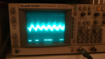
Analog measurement front-end: the signal from the commutator is quite noisy. I'll need some analog front end to filter it before reach the ADC (or digital) input of the MCU
RPM measurement theory:
A motor is a highly inductive load. When the commutator switches from one coil to the next one the built magnetic field is not able to change as quick as the current changes. This generate negative voltage spikes on the motor poles. This spikes must be filtered out with a parallel diode. If we measure the current through this diode, we can find the these spikes and calculate the actual rpm from the frequency of it.
 SUF
SUF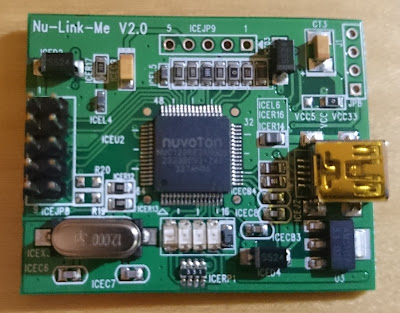





 Yann Guidon / YGDES
 Marcos
 Jose Ignacio Romero
I really like what you've done! I had never thought of counting commutator spikes to derive rpm. I always used an encoder. Clever stuff. I'll be keeping an eye on this project, as I may design a similar spindle controller for my 3040 one day. Thanks for sharing your work.
Johnny.