-
Front Panel Board Build
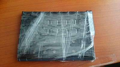
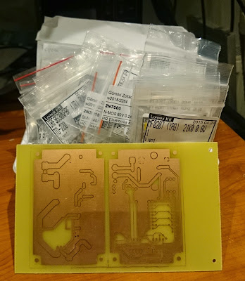
08/13/2015 at 13:39 • 0 commentsMore than a week ago the boards finally arrived:
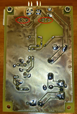
Then I soldered the parts into it:
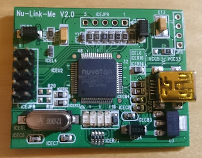
I picked one of my Nuvoton development board, cut it to it's parts, and soldered the missing headers, to be able to use it as an ICE programmer/debugger:
Finally, I started to rewrite the controller's program, to the new pin configuration. During this process, I also want to little bit clean up the code.
To test the board is working, I wrote a "Hello World" for it. :-)
The board looks like working so far. The next step would be to finish the conversion/clean up the code.
-
Front panel design finished
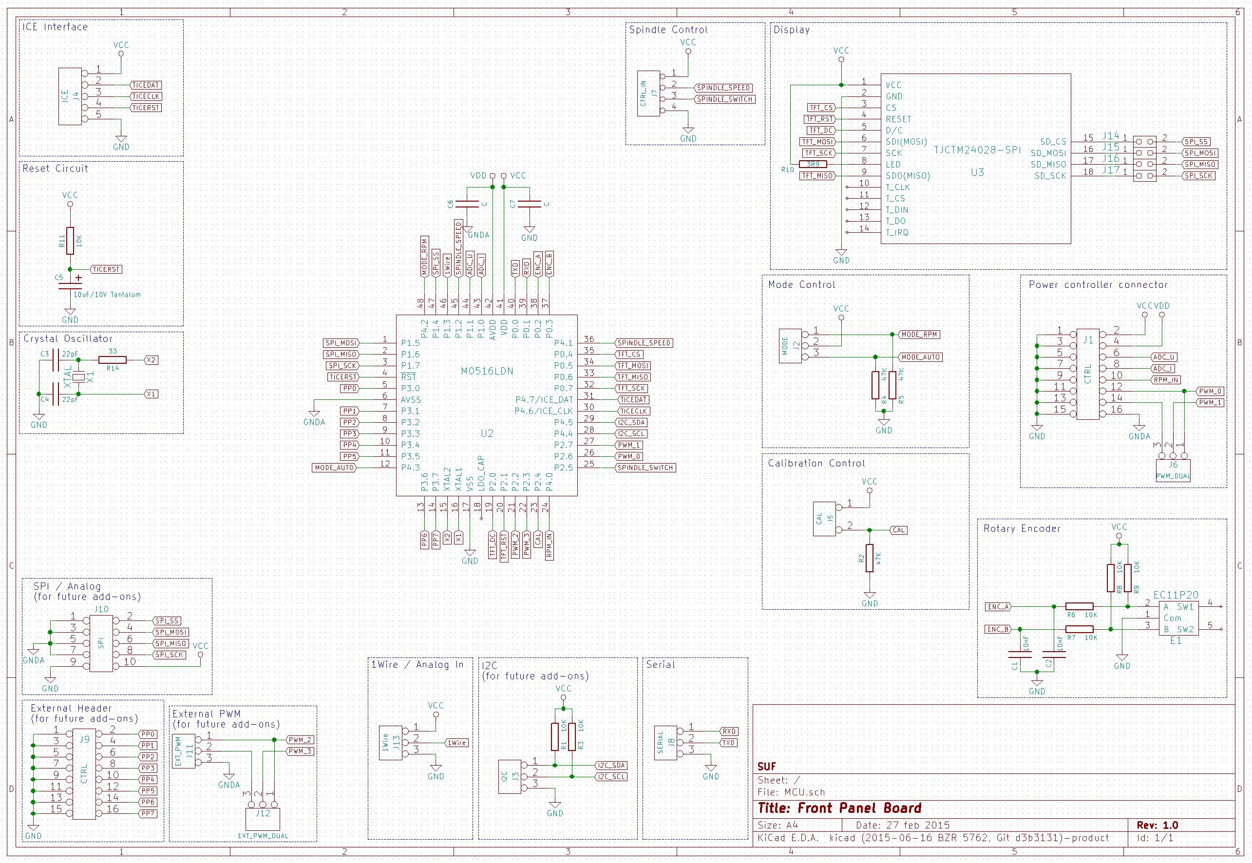
07/20/2015 at 04:01 • 0 commentsAs I promised my previous post, I made some tweaks on the front panel schematics. To be precise, connected the push button of the rotary encoder to the MCU. This gives me the flexibility to use the rotary encoder to navigate in some kind of menu system (if I write some code for it), able to eliminate the additional physical controls (mode switch, calibration switch), and provide the possibility to add more function. Here is the modification of the schematic drawing (actually I can't insert the full page here - lack of resolution of the computer where I'm writing this actually. All of the drawings can be downloaded from the github repo)
I think, the current schematic will be the final one, if I don't find any additional problems with it. So I designed the board:
And ordered it form the dirtypcbs.com
Waiting to arrive... -
Learning Chinese :-), front panel schematics
06/22/2015 at 13:33 • 9 commentsReverse Engineering the CNC control board
During the weekend I was trying (still unsuccessfully, but I don't give up) to get the PWM signal generated by the LinuxCNC out from the parallel interface/stepper driver board.
I would like to achieve without soldering (just to have some challenge).
First of all, about the board.
The machine arrived with a JP-3163B board in it, plus and additional stepper driver for A-axis. Actually, I'd like to keep this board and I want to get as many things I can out of it. The board in question is a version 3.9.
What I found out, that the documentation widely available (and already mentioned by me earlier here), is not completely correspond to my board. Even, if I check the pictures of the boards in sale currently on the AliExpress and eBay, are the same as mine, but the documentation is the other (in fact for the v3.6).
If we are talking about the stepper drivers, and the inputs that are the same, but the additional secondary relay, the spindle drive, the jumpers, or the LED's for the A-axis are totally different.
The only information I can get is the Chinese text from the board itself (not to much).
Part of the 3.6:
![]()
And the 3.9:
![]()
As you can see the upper has 3 jumpers and the lower has 5. (If you didn't realized, the fifth located next to the parallel connector.
Actually I'm trying to collect as much information about the boards as I can. I found this text somewhere:
现出售的是最新的JP-3163B V3.9版本,增加了延时启动功能和风冷功
能,延时启动是为了更好的保护驱动器不易损坏(风冷为开时,只受Z轴
方向吸合继电器2输出给电磁阀风冷,风冷为关时,做继电器2使用),另
外:本店的手柄只支持以前的V3.7 V3.8 V3.9版本,V3.6版本是不能用
手柄的,请购买手柄的客户买雕刻机手柄时,与店家联系,了解您购买
的板子是否可以配用JP-392Q控制手柄.
Translated (google translate our friends):
Is the sale of the latest JP-3163B V3.9 version, adds delay start function and air-cooled power
Energy, delay start is to better protect the drive easy to damage (air to open, subject only to the Z-axis
Direction of pull solenoid valve relay 2 output to air cooling, air cooling is off, do use relay 2) and the other
Outside: We handle only support the previous version V3.7 V3.8 V3.9, V3.6 version is not used
The handle, the handle when your customers buy buy engraving machine handle, contact with the store, understanding your purchase
Whether the board can be used with JP-392Q control handle.
This is far from perfect, but at least we can see that some changes in the cooling and the delayed start is added somehow to the spindle drive.
About the LEDs, specially the upper three. On the original board I seen somewhere else English text stating the following:
LED1 (Red) - PWR - Power
LED2 (Green) - A-OR - A-axis direction
LED3 (Green) - A-PU - A-axis step
On my board:
LED1 (Red) - 电源 - Power supply
LED2 (Green) - 主轴 - Spindle (Pin 1 of the parallel port)
LED3 (Green) - 使能 - Enable (Pin 14 of the parallel port)
I also tried to get some information about the jumpers
JP1 - 内 5V / 外隔离 - Within 5V / outer barrier (Internal 5V / External supply ???)
JP2 - 使能开 / 关 - So able to open / close
JP3 - 风冷开 / 关 - Air cooling on / off
JP4 - 模拟量开 / 关 - Analog On / Off (When I switch this of the previous constant 10V disapear from the spindle control)
JP5 - 手控开 / 关 - Manual on / off
Some of the pins of the parallel port are working differently (or has connection to the Spindle control) than it written on the documentation I found:
1 - Spindle On/Off
14 - ??? (Switch On/Off the LED3, but I didn't found any other impact yet)
16 - Realay 2 (It clearly switch on and of the Relay 2, instead of the stated NC)
17 - ??? (Actually I didn't found any impact, it may NC)
This is the current status. I didn't have more time to work on it. I'll definitely continue this, until I'll able to get out the PWM signal in some way.
Front Panel Scematics
I finished the first version of the front panel schematic design. It is in the github repo:
I'd like to add some comments to it:
1. I added lot of external connectors what will not be used but give place for future development
2. The controls are still fuzzy. I may change some hard buttons to a menu based something controllable via the rotary encoder and it's button. This need some tweaks in the hardware also. This means, the schematic will get some slight modifications before the PCB design.
3. The software spindle control has no additional circuit, it is just two pins now on a connector. It will be an add-on board with maybe some protection diodes, level shifting circuit, or optocouplers. It will be based on my finding in the first part of this post. On the other hand, I do this, because this keep the things open to connect different kind of CNC boards.
4. The MCU pins are significantly different from the ones are on the current software implementation (the software will be aligned later). The cause of this, is a misinterpretation of the MCU pins by me. I mixed up the ADxx pins with the AINx pins. The first is external digital parallel bus, what I don't use, and the later is the inputs of the AD converter.
-
Logic PSU - Testing
05/31/2015 at 05:02 • 0 commentsYesterday I soldered the parts into the board, I realized three mistakes, what I made.
The designed connectors are bigger, than what I wanted. So I 'll have 3,96 mm spacing connectors, instead of the 2,54 mm ones.
Drilled a 1,5 mm holes for the connectors instead of the required 2 mm ones. Fixed easily.
There is an additional LC filter at the output of the circuit. I designed a 100uF/6,3V B size tantalum capacitor into it, but I bought 100uF/10V D size ones. I was thinking. Is I not solder this now, will this prevent me from trying the circuit out. Not. So I just keep it this way, and buy new caps on Monday.As I finished the build, I wanted to test it. I was specially interested in the noise generated by the circuit.
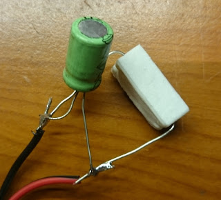
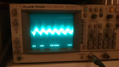
As I had no cap in the output LC filter I soldered an old 100uF cap directly to the testing 470ohm load resistor, and tryed to figure out the noise generated.
It was so low that I can't find it in the enviromental noise picked up by my oscilloscope.
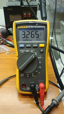
And finally the output voltage is good enough.
-
Logic PSU
05/28/2015 at 22:27 • 0 commentsIn the mean time I designed the test circuit/board for the power supply of the low voltage parts of the circuit. The MCU, the measuring amplifiers, the display will run from 3.3V (I planed to use 5V supply originally, but the display I'm using is not able to run from it). This supply finally not as cheap I wanted to have. It was clear that I need a switching mode supply, and a chip with high voltage capability. I know that a few hundred milliamps is not to much, and the whole circuit is powered from the mains and not batteries. This is a good candidate for some three leg standard regulator or LDO, but...
Always, that but.
the whole circuit will run from a single 48V supply. Generating just 100mA with a standard regulator means you have to dissipate 4.47W on the regulator. In addition the standard three leg regulators are not designed for 48V input voltage.
So the decision is to use HV buck regulator. Especially the LM2594HV-3.3 model from TI.
I designed a circuit around it:
And a PCB for testing:
The finished board (population come later):
-
MCU Arrived
05/28/2015 at 13:51 • 0 commentsWhen I started this project I selected Nuvoton's M054LDN for it. It has 16+4K FLASH what looked enough to me. I have an M0516LDN based development board in my hands, so I started to write the code on it. As the project advanced it become clear, that the code will not fit into the 16K. There is two factor behind it: the character table used for the graphic display, and the floating point library used by the PID controller.
But there is a problem. At the local reseller I just found the M054LDN and the M0516LAN and not the M0516LDN. This A instead of D means something here. It is the revision of the device. Together with other changes the rev D. has FIFO capability on the SPI interface what I'm extensively using for the display driver, and really don't want to throw it away.
So I looked around, and found what I needed on the AliExpress.
It arrived also this week:
-
V2 Testing
05/28/2015 at 03:54 • 0 commentsOn the weekend, I finally get to run the first test on the V2 MOSFET driver.
I just connected it to the bench PSU, and the MCU, added a resistive load (a 470Ohm/5W resistor) to it. Switched on, and...
Nothing happened.
Looked around, trying to find the error.
On the input, the PWM signal was there.
On the low side small FETs the signal was there.
On the MOSFET's gate... nothing was there.
I turned the board to see the soldering side...
Idiot!
After soldering the MOSFET and the diode, it started to work perfectly.
-
V2 Boards
05/05/2015 at 09:05 • 0 commentsI planed to build the new motor driver during the weekend, what unfortunately doesn't happened. It took an additional week. What I want to mention here, that together with the motor driver I also designed a new measurement circuit. This one is able to measure not just the rotational speed but the current (it was also in the previous but untested) and the voltage of the motor. In addition I included the necessary protection diodes what was left out from the previous one, and a configurable fifth order low pass filter to test the filter for the final design.
Here is the schematic diagram:
And the PCB design:
The first weekend achievement - etching the boards and collecting the parts:
A week later - the boards cut, populated:
The next things to come (not necessarily in this order):
- Test this two boards
- Design a home made pcb for MCU+Display
- Add additional filtering into the adjustable DC
- Design and build the last missing piece - the high voltage input 3.3V PSU
- Test and tune the PID controller code
- Move to the final PSU from the lab supply
- Put everything together - write the code for the rpm setting from G-Code
- Write the code for the voltage/current/power measurement
- Design and order the final boards
- Build everything into the original controller box
-
MOSFET driver revised
04/25/2015 at 21:36 • 2 commentsI was thinking, looking around a lot before I designed and built the current motor driver circuit. I wanted to use something cheep, something I can learn from.
The current one is working, but I was thinking, how can I make it a little bit faster. When I designed the current one, experimented lot on the breadboard, but not used ltspice to simulate the circuit. When it was finished, I needed to tweak it, here and there, to be able to reduce the noise for the clear measurement signal.
Now I'm trying to get faster switching, to reduce the heat generated by the MOSFET.
First of all I run a simulation of the original circuit.
The circuit:
And the result:
As you can see the the timing results:
Switch on time: ~500ns
Switch off time: ~500ns
After 2-3 weeks of continuous (in my spare time, what I not really have to much) simulation, changing components, pursuing different ideas, finally I created a little bit better one.
The circuit:
And the result:
And the timing:
Switch on time: ~30ns
Switch off time: ~100ns
Much better.
Based on the things above, I designed a little bit different circuit. The reason: I use mostly trough hole components for the home made PCB and switch to SMD when I order the final one.
The schematic
And the PCB design:
Hopefully I'll be to build it during the weekend.
-
The MCU control works!
04/06/2015 at 22:05 • 0 commentsSince the last post regarding my CNC Motor Driver, in my spare time I was continuously working on the MCU board and the software for it.
Today finally I see the end of this project's. I'm trying to collect the thing still need to be finished:
Two days ago I connected the digital part to the power electronics. It started to work immediately, but unfortunately the rpm measurement was messy.
After some thinking and trying, I realized, that the source square wave has some narrow pulses around the edges, what are messing up my measurement.
The Nuvoton MCU I'm using is able to add some de-bouncing delay to the timer's capture input. Adding this feature looks like solving my problems.
- Test and tune the PID controller
- Try out additional filtering on the power input side
- Try out additional filtering at the motor
- Try out the 5th order filter I designed for the measurement
- Test and write code for the current measurement
- Add voltage measurement solution (circuit and code)
- Add code for power display
- Add code for measuring the control signal from the Linux CNC (this allows the control of the rotational speed from g-code)
- Design a high voltage input 3.3V power supply (actually the 48V input is to much for the regular buck converter chips)
- Design and order (hopefully) the final panel for the whole electronics
- Correct the code for the rotary encoder (it is a little bit problematic today)
- Clean up the code (not modularized enough, many comments missing)
DC Motor Controller for CNC Router
DC motor rotational speed controller for Chinese CNC3040 spindle motor without any kind of encoder
 SUF
SUF