Yesterday I soldered the parts into the board, I realized three mistakes, what I made.
The designed connectors are bigger, than what I wanted. So I 'll have 3,96 mm spacing connectors, instead of the 2,54 mm ones.
Drilled a 1,5 mm holes for the connectors instead of the required 2 mm ones. Fixed easily.
There is an additional LC filter at the output of the circuit. I designed a 100uF/6,3V B size tantalum capacitor into it, but I bought 100uF/10V D size ones. I was thinking. Is I not solder this now, will this prevent me from trying the circuit out. Not. So I just keep it this way, and buy new caps on Monday.
As I finished the build, I wanted to test it. I was specially interested in the noise generated by the circuit.
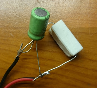
As I had no cap in the output LC filter I soldered an old 100uF cap directly to the testing 470ohm load resistor, and tryed to figure out the noise generated.
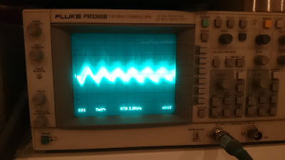
It was so low that I can't find it in the enviromental noise picked up by my oscilloscope.
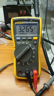
And finally the output voltage is good enough.
 SUF
SUF


Discussions
Become a Hackaday.io Member
Create an account to leave a comment. Already have an account? Log In.