Close
0%
0%

JACA 1 & 2 Homebrew Computer

JACA - Just Another CPU Again
Homebrew CPU, starting by a simple POC 4-bit CPU on circuit simulator soft. (done), then 8-bit (in progress)

Similar projects worth following
The ultimate goal is to make (physically build) from scratch a complete computer as simple as possible, but powerful enough to run old games such as Tetris, Pong, Arkanoid or Snakes on a LED matrix (probabily 16x16).

Edit: check it out for the latest version of project files on GitHub:

https://github.com/albs-br/jaca

The ultimate goal is to make (physically build) from scratch a complete computer as simple as possible, but powerful enough to run old games such as Tetris, Pong, Arkanoid or Snakes on a LED matrix (probabily 16x16).


In order to do this (and have something working earlier) I decided to make first, as a POC, a very simple 4 bit CPU in a simulation software (Logisim 2.7.1).


This 4 bit CPU has the barely minimum to do some useful computing, in this case I chose a multiplication of two 4 bit numbers.
Hardware specifications:
-4 general registers of 4 bits (A to D)
-RAM memory of 16 words of 8 bits
-initially just 8 instructions, with 3 addressing modes (no instructions of memory access at this point) (*)
-fixed instruction size (8 bits, one cell of memory)


This last point I consider vital for the simplicity of the circuit, since I need only one access to the memory to get all the instruction, making the Fetch fase the simpler I could imagine.


There are only two steps cycles per instruction, Fetch and Execute. Two clock lines are used, one to properly set the inputs of the devices and other to trigger the clocks and commit the changes.


The ISA is heavilly influenced by that of MSX, which I used to program back in the early 90's. That was an 8 bit computer hugelly popular in my country (Brazil), despite almost unknown in the rest of the world.


It uses a Load/Store architecture, meant that all operations are done over the registers, the only instructions to access memory are Load/Store to or from a register. There is is no way to add two numbers in memory directly, for example. As all other design decisions that was for the sake of simplicity.


(*) Later in the project I could squeeze even more the ISA and insert two instructions to make memory access, but this is not necessary to the initial goal (multiply two registers).


Initial research and study on the subject was done late March 2017, I spent maybe two weeks choosing the simulation software (there are lots of options, even web based ones). Circuit design itself started one month ago, and, as of May is, I'd say 80% done. The pace seems very slow, but I could manage to effectively work on the project just 1-3 hours/week...

PS: the name JACA is a (bad) joke with the portuguese name of the jackfruit, common in Brazil.

  • 2 × 74LS181 4 bit ALU
  • 1 × 62256 32k x 8 bit SRAM
  • 5 × AT28C256 Memory ICs / EEPROMsEEPROM 32k X 8 bit
  • 13 × 74ALS874 8 bit register with async CLR and 3-state outputs
  • 10 × 74LS154 4 to 16 demux

View all 8 components

  • Reviving the project

    Andre Baptista01/19/2020 at 18:26 1 comment

    One year ago I made a commitment to finish this project in 4 months, one module per month (link). The first 3 months everything went alright, but the last module was very complex and blow up entirely the schedule.

    Now I'm slowly coming back and putting this module on a PCB, this time without time contraints, just for fun.

  • Changing of plans

    Andre Baptista09/13/2019 at 18:40 0 comments

    Hi friends. For those of you still interested in this endless trap I've got into, some update on the situation:

    This last module is by far the hardest. I tried first on breadboards, then universal PCBs, then breadboards again... Each of them with his own pains and suffering.

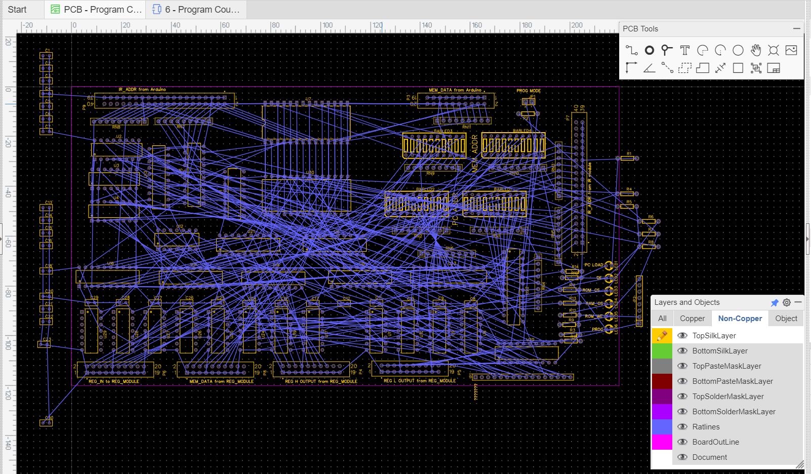
    Now I'm changing the approach and doing it on custom designed PCB, as all the other modules. The reasoning is that the basic functionality is already proved on breadboards and for the others is very hard to deal with soooo many jumpers lying all around and that's driving me crazy.

    So I will design a PCB that leave "room for error" on the untested parts, that is, the fundamental ICs connections will be left open and connected on the soldering phase.

    I hope that works. Will be finalizing the design and ordering the PCB board soon.

    Thanks for reading.

  • Project stalled...

    Andre Baptista08/15/2019 at 21:46 0 comments

    No progress at all last weeks... Work and family taking up all my time.

    Hope it gets better soon.

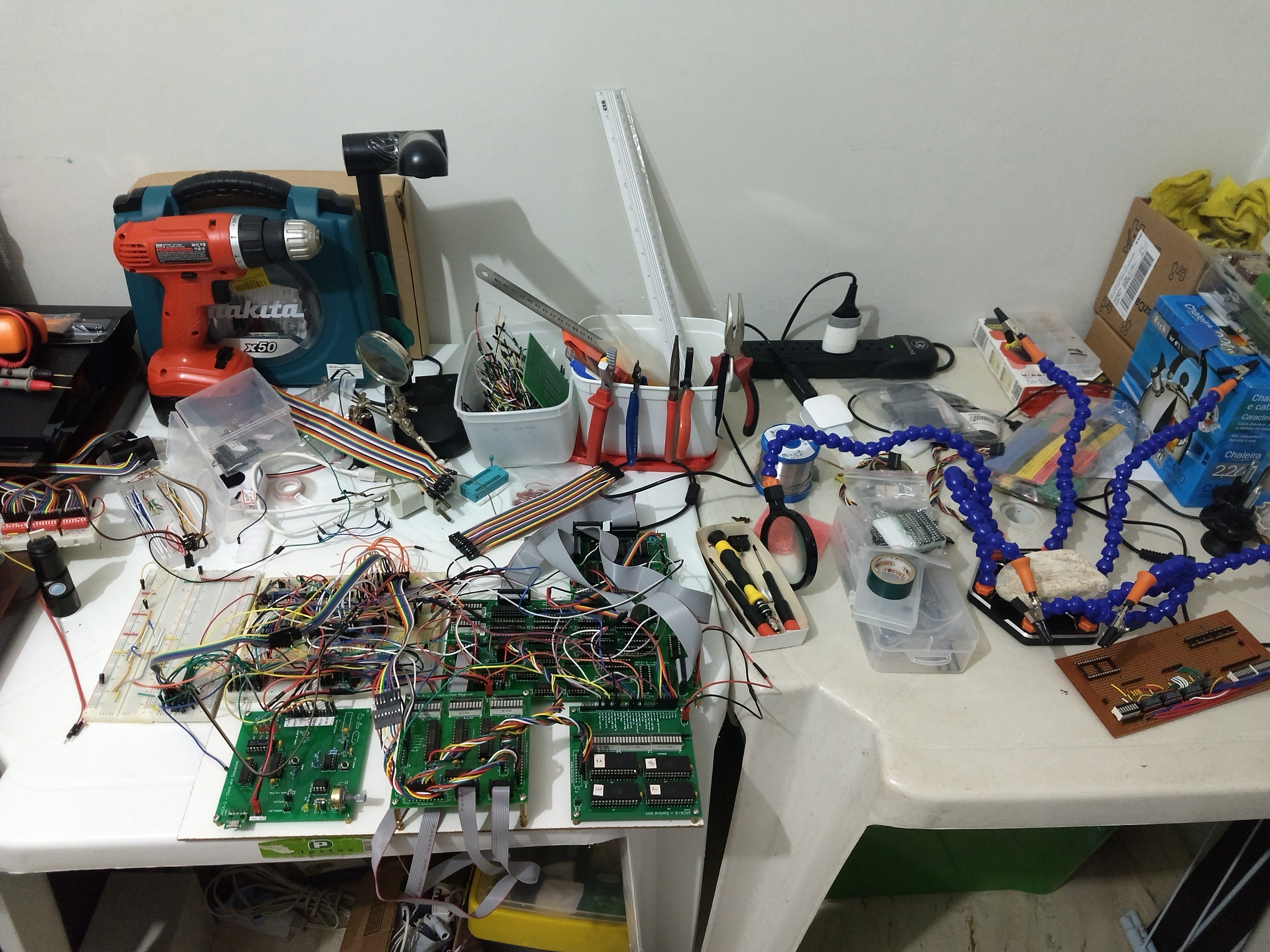
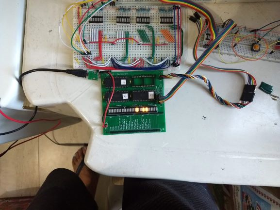
    Meanwhile a picture of my underused electronics desk:

    Thanks for reading.

  • Running an entire program

    Andre Baptista06/27/2019 at 21:47 0 comments

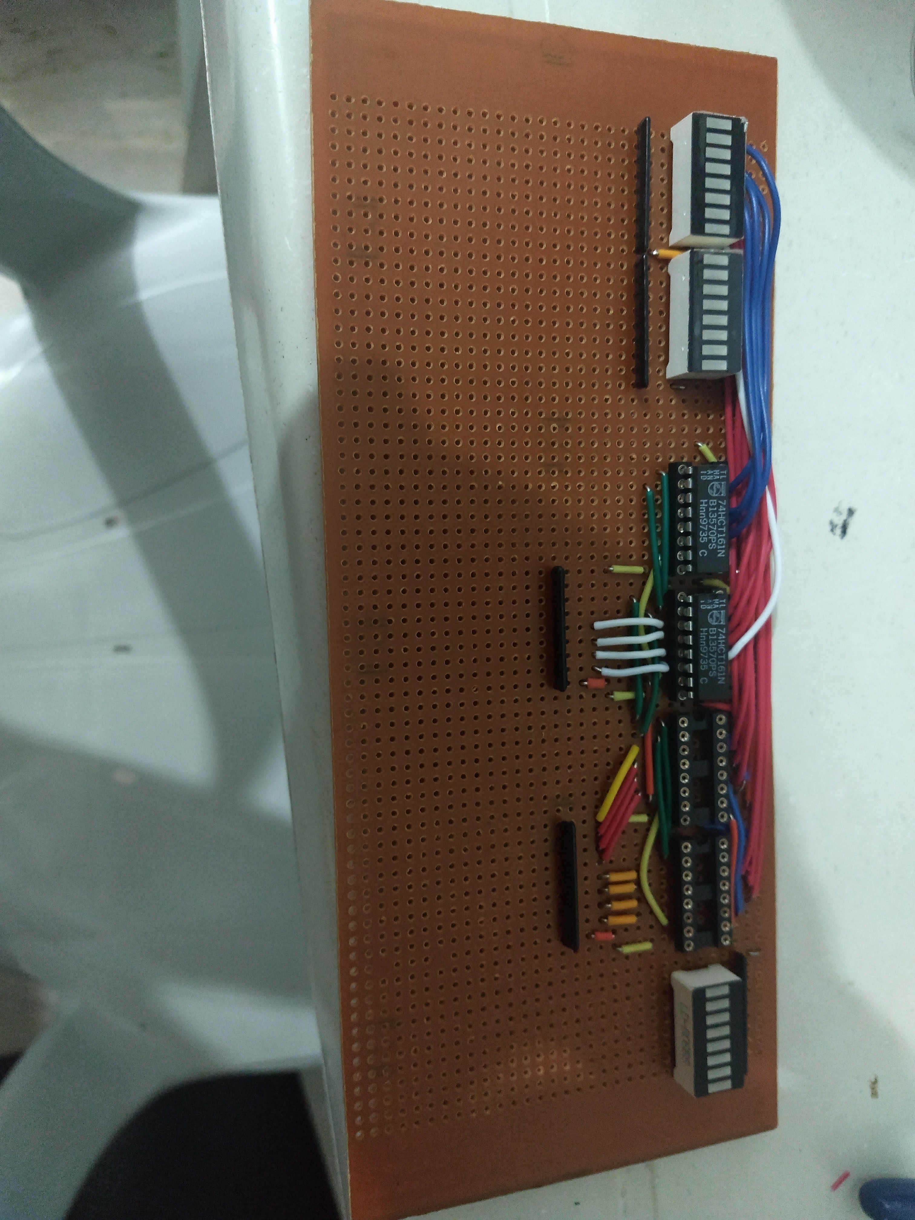
    I'm back again to the breadboard for this last module, as the work of soldering dozens of wires on the universal PCB was huge.

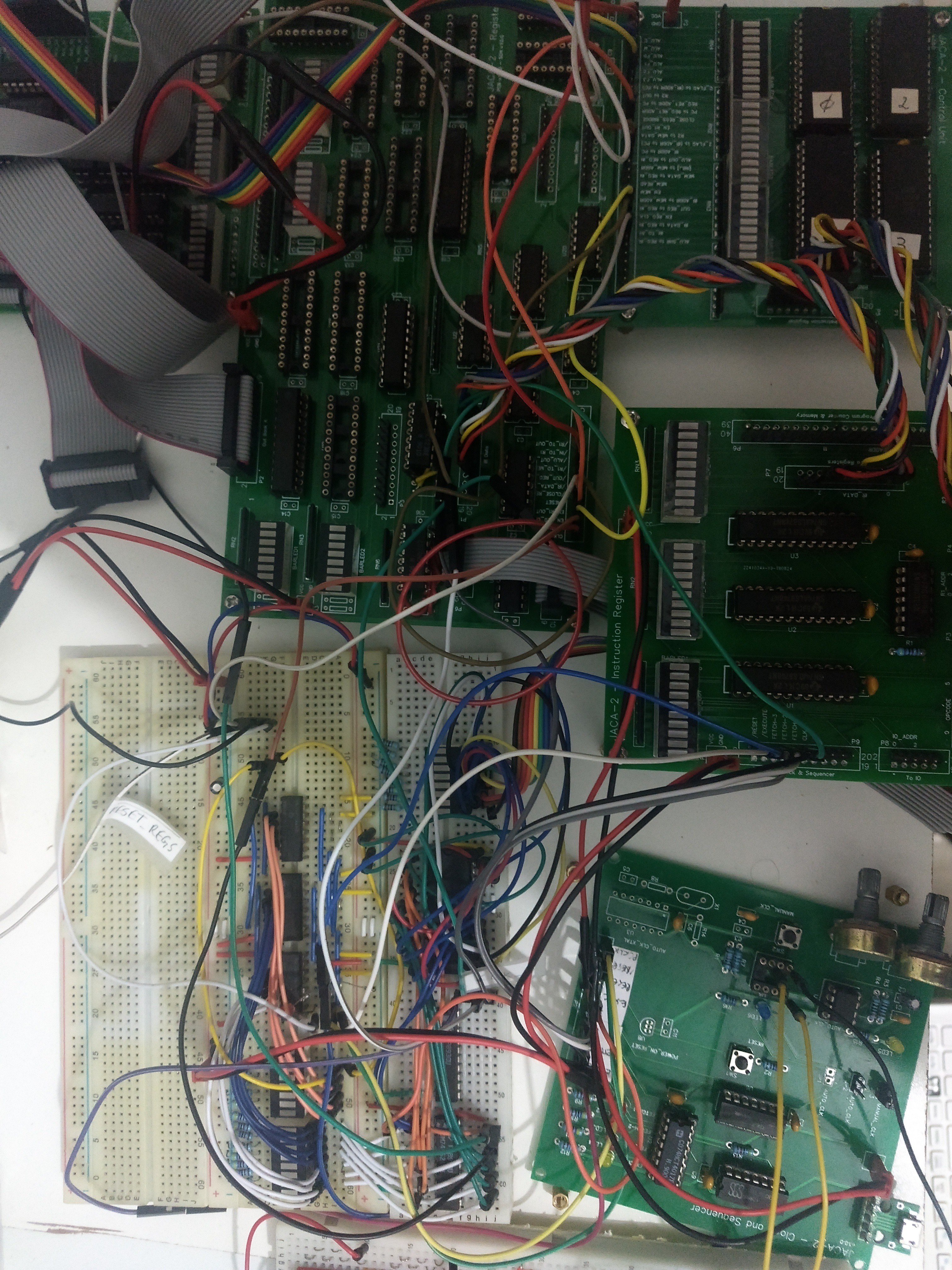
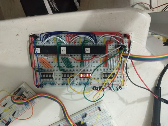
    So I managed to make the PC and Memory module on a breadboard and run a simple program, with conditional and unconditional jumps:

    The program loads the 32 value into A register and increments it until pass 255, then stops.

    Thanks for reading.

  • Project status

    Andre Baptista06/05/2019 at 16:42 0 comments

    According to the plan I made on December 2018, I'm already more than one month late.

    Let's see what we have currently:

    - Registers board built. Registers A and E working. Loading literals (e.g. LD A, 5). The other 6 registers are just a matter of insert on DIP sockets and reprogram the EEPROM to write code to test them. Lacks testing the copy from one register to another.

    -ALU connected and working (at least the ADD instruction). Saving result to register fine.

    -The Program Counter and Memory, which is the only module still on breadboard is being redone on a universal PCB. That's a more demanding work as it seems. Some 8 hours of soldering estimated. At my self imposed pace of 1 hour per day, it's very slow to see progress. After that I will need to put circuit to manage the conditional and unconditional jumps.

    Write down these logs help me keep motivated as it's easier to see progress looking behind.

    Thanks for reading.

  • JACA 2 emulator in JavaScript

    Andre Baptista05/02/2019 at 20:41 0 comments

    Meanwhile I made a small emulator for the CPU in JavaScript using the awesome Stackblitz environment (not finished yet): 

    https://jaca-emulator.stackblitz.io

    Not all opcodes implemented, but already run sample code preloaded.

    Thanks for reading.

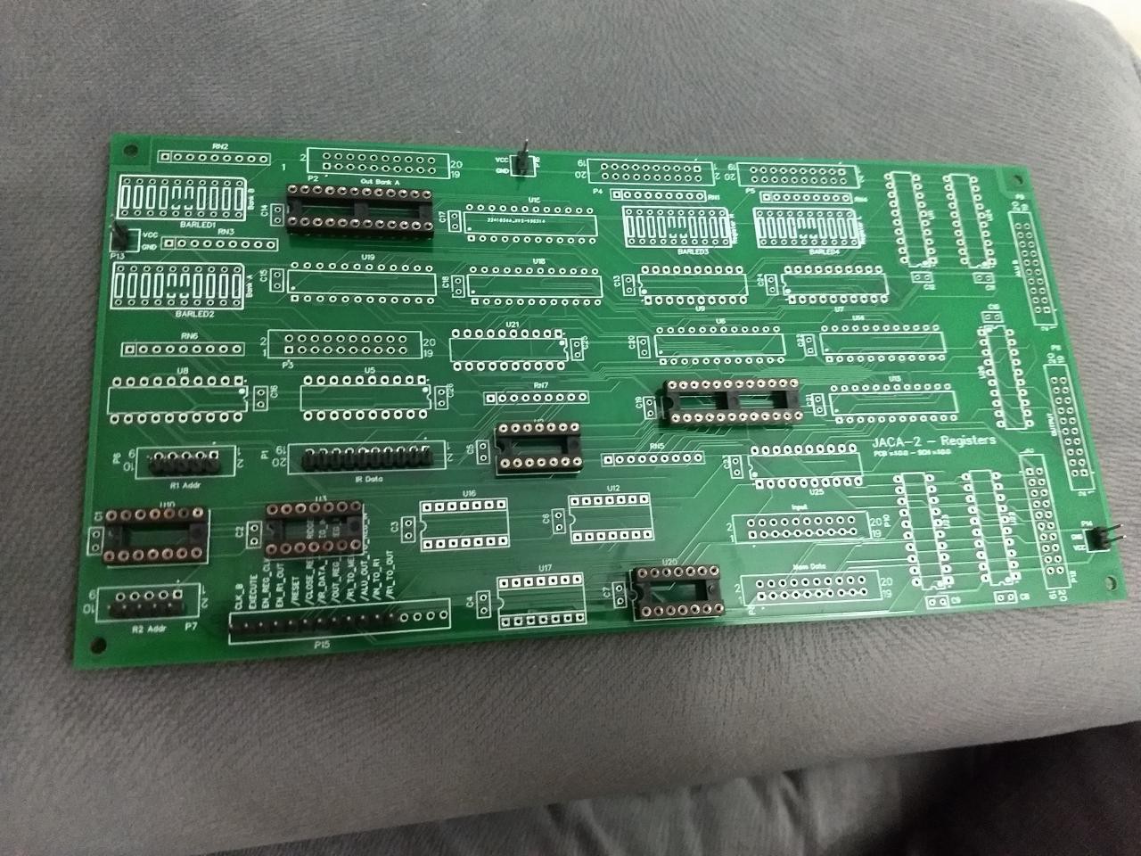
  • Registers board (finally) arrived

    Andre Baptista05/02/2019 at 20:24 1 comment

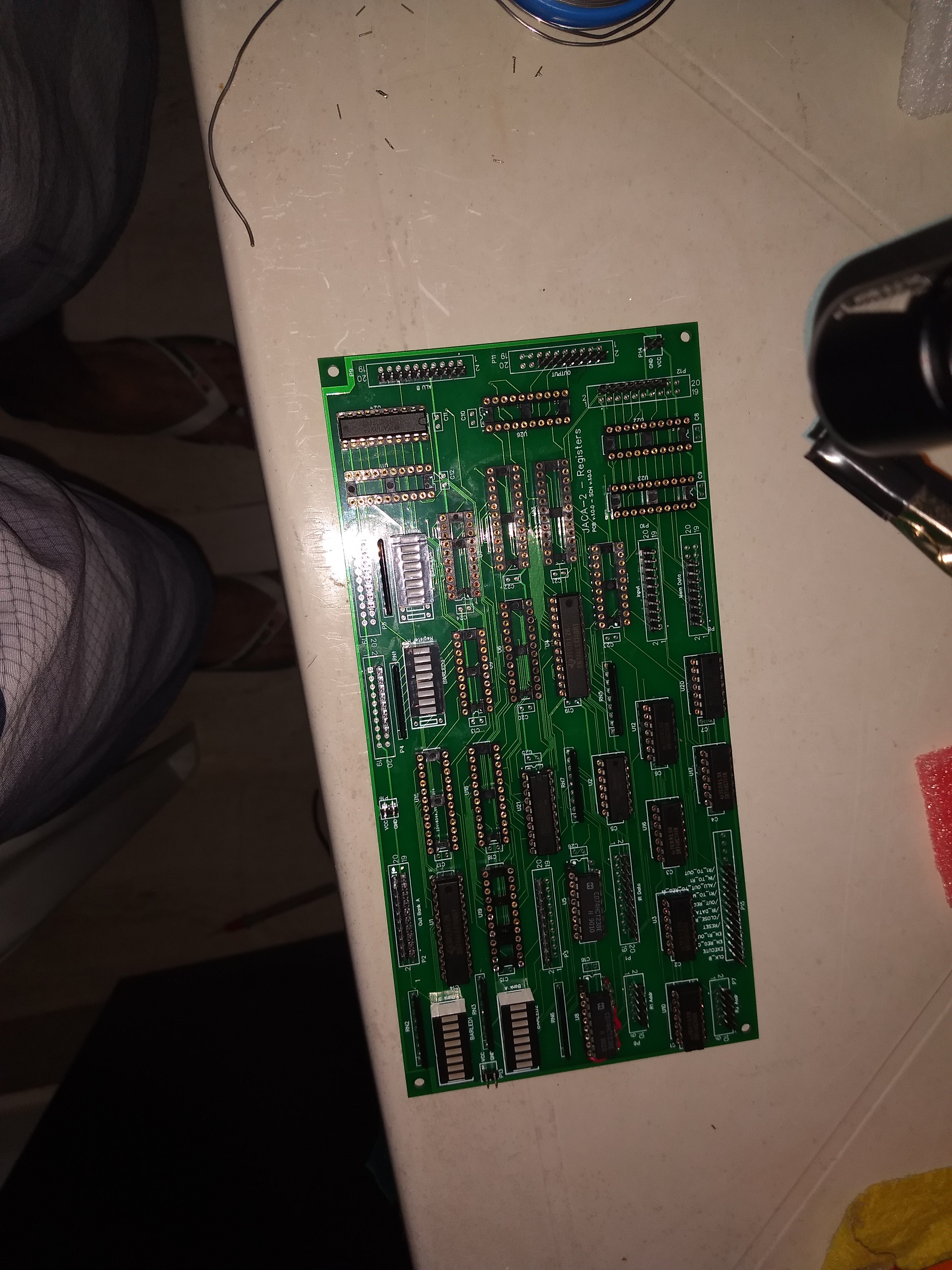
    After a long wait the PCBs are finally home and as I started soldering the IC's sockets I noted a mistake on the very first: the 74HCT238 is DIP 16 and on the board are DIP 20... The IC footprint are pre configured on the EasyEDA but I have the fault of not revising one by one...

    Well, life goes on and no way to wait another 6 weeks and spend more US$ 40, so I will make a ugly workaround to solve this.

    Thanks for reading.

  • Control Unit migrated to PCB

    Andre Baptista03/14/2019 at 00:44 0 comments

    Project update:

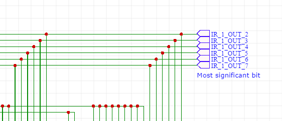
    • as the post's title implies, Control Unit is now living on a PCB, a life form hundreds of years ahead of the breadboards, but not without some pain... As always there was a mistake on the PCB desing, but this time it wasn't my fault: the EasyEDA software has a trick (or more apropriatelly, a bug) and it doesn't connect wires in a specific situation, like this:
    These wires are NOT connected with the Labels... I'm not sure what's the cause, maybe a small misalignment on grids

    Before
    After
    • Registers board was ordered today. As it is twice the size of the others (and three times the price) I took special caution to not make mistakes. I hope everything will be fine. Now the only thing to do is to wait, around 30 days for the board to arrive.

    Thanks for reading.

  • Testing ALU

    Andre Baptista02/26/2019 at 00:40 0 comments

    Some days ago I made a video of the ALU testing. I had some surprises with this module: the power wires were too thin, which, together with the cheap eBay ICs was causing a voltage drop; I made some mistakes when designing the PCB which I had to correct with very ugly wires.

    PS. Today one more board arrived, soon we will have a new module working.

    Thanks for reading.

  • ALU working. Damn cheap Ebay ICs

    Andre Baptista01/20/2019 at 19:08 8 comments

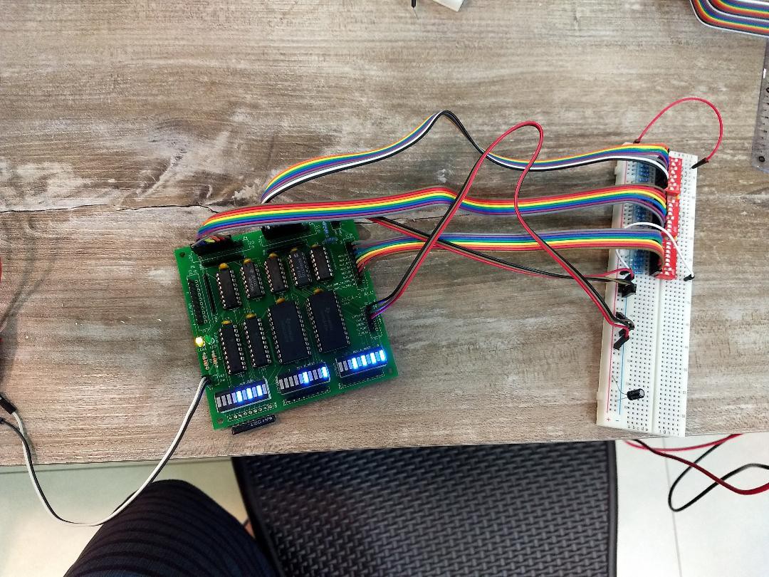
    After two months stuck in this problem, I finally came to a solution: the fault was on cheap chinese ICs from ebay, which caused a huge drop of tension across the board, making VCC on some IC's to fall below 4 V. So, caution with Ebay components.

    ALU working:

    Lets stay focused to finish project within the schedule!

    Thanks

View all 52 project logs

Enjoy this project?

Share

Discussions

Andre Baptista wrote 04/30/2018 at 20:17 point

PS. The 74181 component for Logisim it's not mine, I found out it here: https://74x.weebly.com/blog/library-of-7400-logic-for-logisim.

Also, caution with the versions: the right version of 74181 ALU is the v2, the other ones aren't working correctly. 

  Are you sure? yes | no

Ruud van Falier wrote 05/01/2018 at 07:13 point

I took the correct one then, thanks! :)

  Are you sure? yes | no

Ruud van Falier wrote 05/01/2018 at 07:16 point

Do you know why some datasheets state that "M=L, Cn=L, S=LHHL" will output "A minus B" and some state that it outputs "A minus B minus 1" ?

  Are you sure? yes | no

Andre Baptista wrote 05/02/2018 at 12:25 point

I have no idea. The right output is "A minus B minus 1" as shown in most resources (like the Motorola datasheet). Also I tested in Logisim and its output was  "A minus B minus 1" as expected.

Edit: forget about above. I misread the datasheet ("Active Low Inputs" seems to exist just to make life harder...). Right output is "A minus B". Anyway it's better test by yourself, both in Logisim and with the real IC using breadboards (maybe an Arduino to automatically test all functions with all possible input combinations).

  Are you sure? yes | no

Andre Baptista wrote 04/30/2018 at 19:48 point

You welcome.

This link was very helpful for me: http://www.righto.com/2017/03/inside-vintage-74181-alu-chip-how-it.html

  Are you sure? yes | no

Ruud van Falier wrote 04/30/2018 at 18:32 point

Thanks for sharing all your work. I've picked up your 74181 component and test circuit which helped out a lot in understanding the comparator functions.

  Are you sure? yes | no

Similar Projects

Does this project spark your interest?

Become a member to follow this project and never miss any updates