Andre Baptista
-
74181 with Right Shift?
12/05/2017 at 14:41 • 0 commentsWhen programming my first games for the Led Matrix of this computer in Assembly, I quickly realized how useful it would be the Shift instructions, for example to move left and right a character.
In case of Left Shift, no problem at all, the 74181 ALU has the instruction A PLUS A (check here), which is the same as multiply by 2, or Left Shift one bit.
Unfortunally the Right Shift instruction is missing in this IC, so I had to implement it with a 74HCT244 (eight tri-state buffer), redirecting bits, such as bit 7 to bit 6, bit 6 to bit 5, and so on... It's a little "ugly" design, as it's the only one instruction computed outside of 74181, but I haven't choice (any idea?)...
We are very close to delivery the "production" version of the Logisim circuit, the 1.0.0 version. The "done" criteria was, since the very beginning, the ability to run simple games. I'm working on a Tetris game and already have a very crude version of an Arkanoid (or Pong).
Thanks for reading.
-
Assembler / PCBs (?)
11/30/2017 at 19:38 • 0 commentsUpdating project status...
Gave up making the compiler, at least for now. Reasons:
a) It turned out far hard than it seems previously;
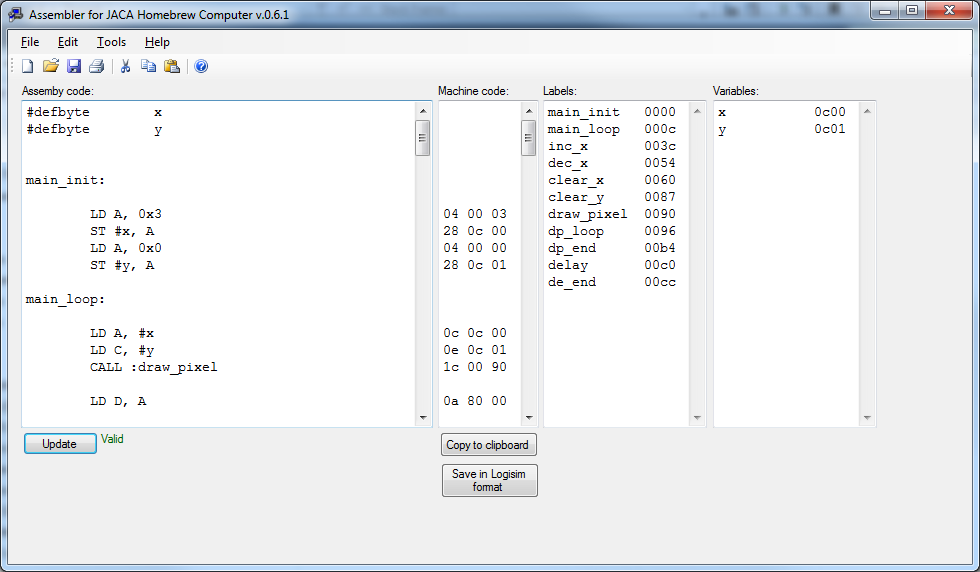
b) Seems for me, now, an overkill. It's not that hard to program right in Assembly (have been watching many videos from WR Kits programming the Z80 in Assembly, it could be fun!), since you have a decent editor and an Assembler to take care of "ugly" things like memory addresses and let the programmer to worry only with the program logic.
Picture of the assembler:
![]()
That is half the story of last two weeks, the other half is:
Thanks to this question I put on Electronics Stack Exchange, I'm seriousy considering make the computer right to PCBs, skipping the possible headaches of the breadboards...
For designing the PCBs I'm thinking of EasyEDA, and for the manufacturing, AllPCB.com.
Any ideas?
Thanks for reading.
-
Update.
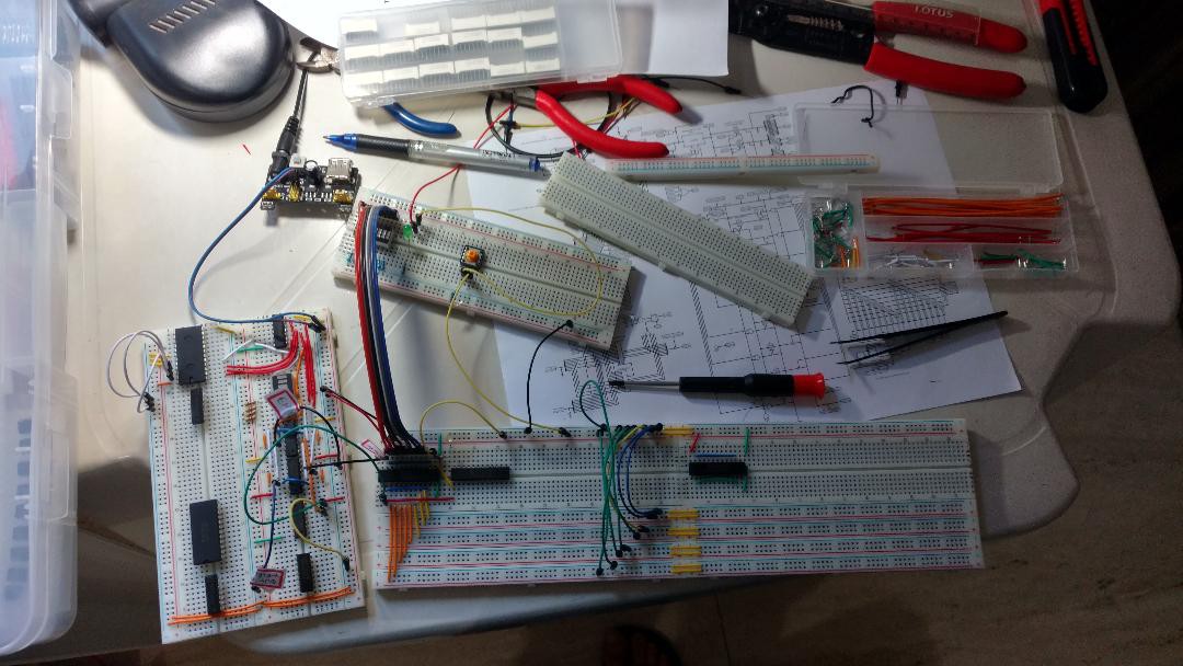
11/16/2017 at 13:46 • 0 commentsAfter a month and a half, I returned to the ICs and wires, making the rest of registers logic and the register A.
Realized I was mistakenly connecting some ICs, as control inputs are active low (most TTLs are) and I have to put a bunch of 7004 (inverters) to make things work.
Now we have register A built and tested.
Almost all of my 14 breadboards were used (some for testing boards) so I ordered 6 more.
As a side note, I noted that the register was losing it's state when I turned off the desk light (!!!). One decoupling capacitor between Vcc and ground lines close to the IC seems to have corrected this issue. I'm afraid of what kinds of interference I will face when running this CPU above 1 MHz...
Some pictures to make this log entry more beautiful:
![]()
![]()
![]()
Thanks for reading.
-
Now we have to code a compiler...
10/24/2017 at 18:40 • 0 commentsLast 2 weeks were very hard to the project... Almost no progress both in Logisim circuit design and breadboards.
I've hit a wall: it became almost impossible to code test programs directly in assembly (with no tool but the Excel to convert to machine code), so I started to develop a simple compiler for a very simplified version of C#. But it (as always) revealed far more dificult than appeared, and the estimated 2 or 3 hours of coding quickly became 10 and far from finish.
Hope to finish this in two weeks at most to return to the main project.
Estimate of completeness so far:
Logisim circuit design: 90%
Real circuit in breadboards: 20%
Compiler: 10% -
Update project status
10/03/2017 at 20:09 • 0 commentsLast two weeks saw some progress although not the expected.
In the Logisim realm, finally implemented the RET_ADDR register, which, unsurprisingly, stores the return address to be used in the CALL isntructions.
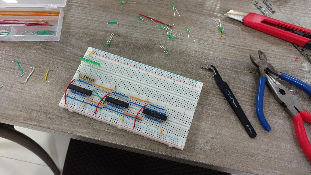
In the breadboards realm, I managed to build the IR (Instruction register), and a (small) part of the registers control logic.
In the "future steps" realm I studied and I am very optimistic about VGA output (maybe 256 x 240 pixels, 256 colors/pixel) and interfacing a regular PS/2 keyboard for input.
That's all people. See you next time.
![]()
Instruction register (IR) with 3 chips (each 8 bits) to hold a 24 bit instruction.
![]()
IR completed.
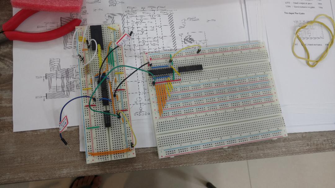
![]() Registers logic very far from completed, with those ugly stickrs to help me remember what each wire is for.
Registers logic very far from completed, with those ugly stickrs to help me remember what each wire is for. -
A little step for a man.
09/18/2017 at 16:32 • 0 commentsThis sunday I finally could make a progress in the hardware part of the project.
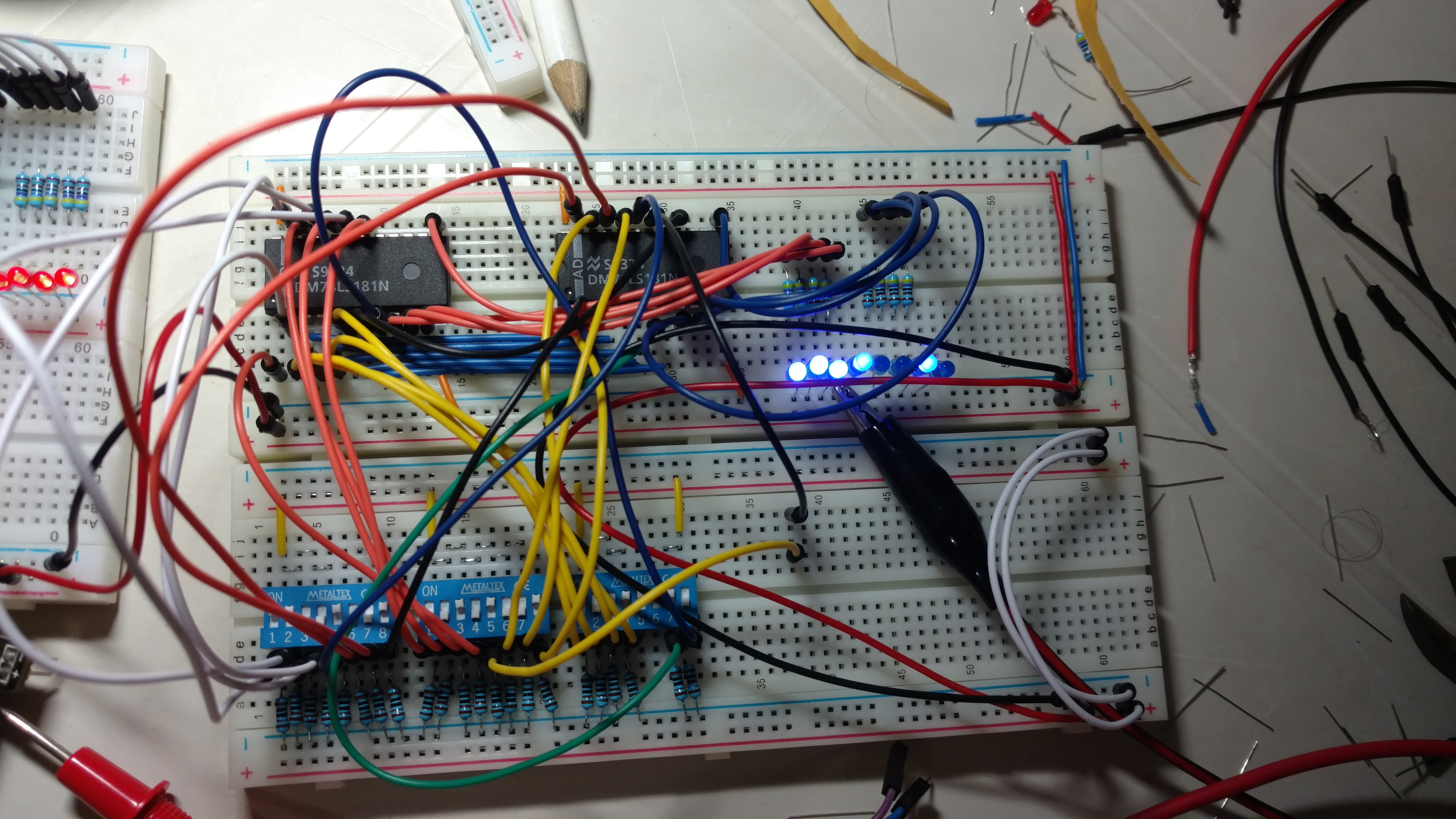
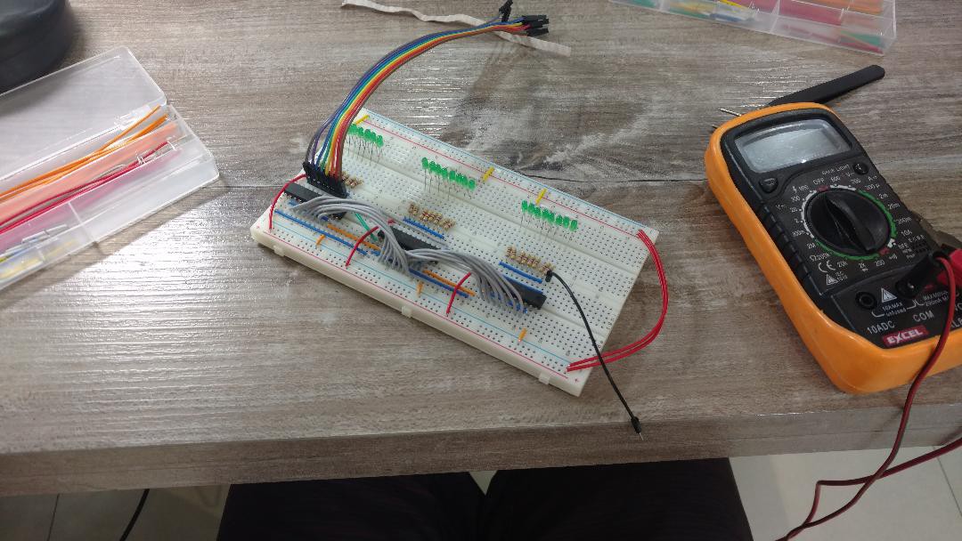
This is the ALU module working, the board below is for test the ALU isolated.
Now showing the sum of 201 (11001001) and 41 (00101001) which is 242 (11110010):
![]()
Some next modules will need code to be writen to EEPROMs, I will use an arduino to accomplish that.
Thanks to follow and see you soon.
-
v.0.15.2
09/11/2017 at 12:04 • 0 commentsAdded a 8x8 LED matrix to the circuit in Logisim, already showing simple animations. I'm not sure if this part should be implemented in real hardware, or skip to a VGA output...
The problem is that the LED matrix haven't any kind of memory, so I'm using a handful of registers to store actual display state. It will be a lot of IC's in real world, doesn't look much like an elegant solution. Maybe I could map screen memory in the RAM and use a fast clock to always refresh the display. We'll see.
Some changes in OUT instruction were needed, all test programs were reassembled (painful and boring task), but all working fine right now.
Next step is to implement an input device (keyboard or joystick) in Logisim, to make the first draft of a game, maybe a Tetris clone.
PS. Now I have all parts necessary to make the CPU in breadboards, maybe next weekend will see big progress.
Thanks for reading.
-
Weekend update
09/05/2017 at 02:42 • 0 commentsv.0.14.0 Big changes.
- Reorganized instructions. As Opcodes changed, all test programs must be reassembled (not finished yet).
- Implemented some new ALU instructions such as XNOR, INC and DEC. Add new ALU instructions is pretty simple, just add new lines to Microcode ROM.
-The main change: now there are two registers called H and L, which will be used to addressing in Direct By Register instructions, containing the High and Low parts of address. These two fix registers replace the previous idea of use any pair of registers [RR3]. Also added one controlled buffer (called Regs Bridge) to separate the outputs of the registers into R1 (A, B, H and L) and R2 (C, D, E and F). This overcome the old limitation that the ALU operations had to use always A register as first input. Now it's much more flexible, R1 for first input (and output also) and R2 for second input.
New control lines were added to the circuit, and Microcode had to be rewritten.
Maybe I've forgotten something. Hope I didn't...
Very busy (and fun) weekend.
Edit: forgot to mention: all this work only in virtual world (Logisim). Real hardware is stuck as the extras 12 breadboards I've bought still didn't arrive...
-
Clock, Phases, and PC working
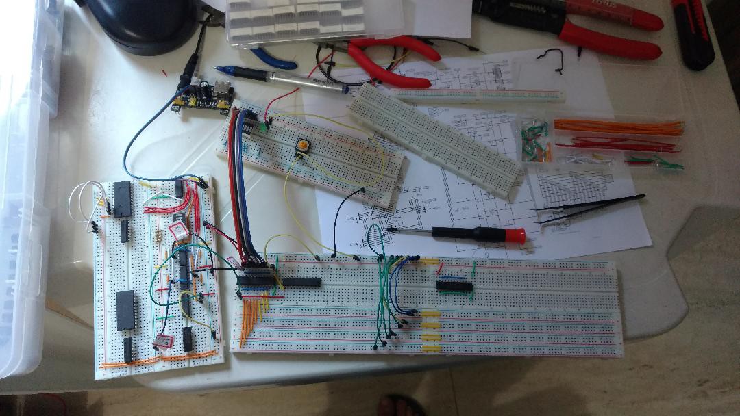
08/28/2017 at 20:00 • 0 commentsFinally, as most of pieces arrive, I could dive into the breadboards and wires and ICs all weekend.
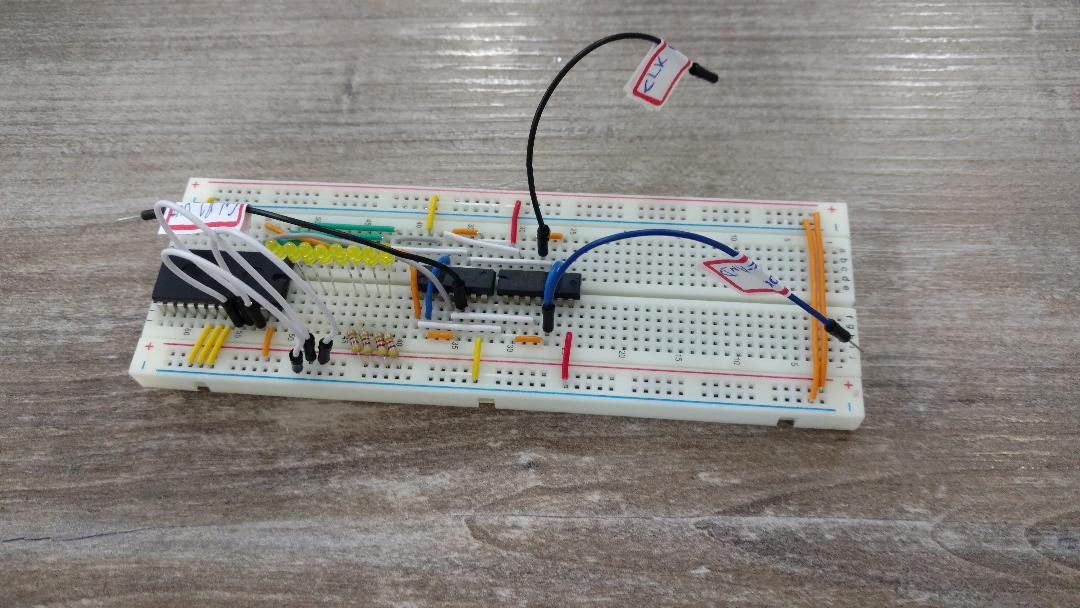
Now we have the Clock, Reset, 4 Phases (Fetch 1 to 3, Execute) and 12-bit PC (Program Counter) fully operational.
Lessons learned the hard way:
-The clock generator 555 IC has very weak output. It barely can feed two TTL inputs. If I put a single 3mm round led (with a huge 4,7K resistor) to see the clock ticks, it makes all the circuit to behave erratically. That is why all projects out there uses an buffer/inverter right after the 555 output to feed all the circuit.
-Baby steps, allways. The old and good XP (eXtreme Programming) mantra is especially true when dealing with (moody) hardware. For each single piece added, turn on the circuit and see if everything still runs fine.
-TTL outputs are not suited to drive leds directly, but as i'm using big resistors (4,7k as mentioned above), the current is very small (between 0,3 and 0,8 mA, depending on the TTL output, which can vary bettween 5 and 2.7 V). Surprisingly the leds show a useful bright even with such tiny current, so I can use them without bother with transistors to drive the leds.
I never felt so happy to see a bunch of leds blinking :)
Unfortunally the 6 breadboards I ordered a long ago still didn't arrive. I will buy them on local market anyway.
![]()
![]()
-
Update after long time, real hardware.
08/06/2017 at 18:10 • 0 commentsHello, first log entry in a long time... Trying to keep the project up while solving personal issues.
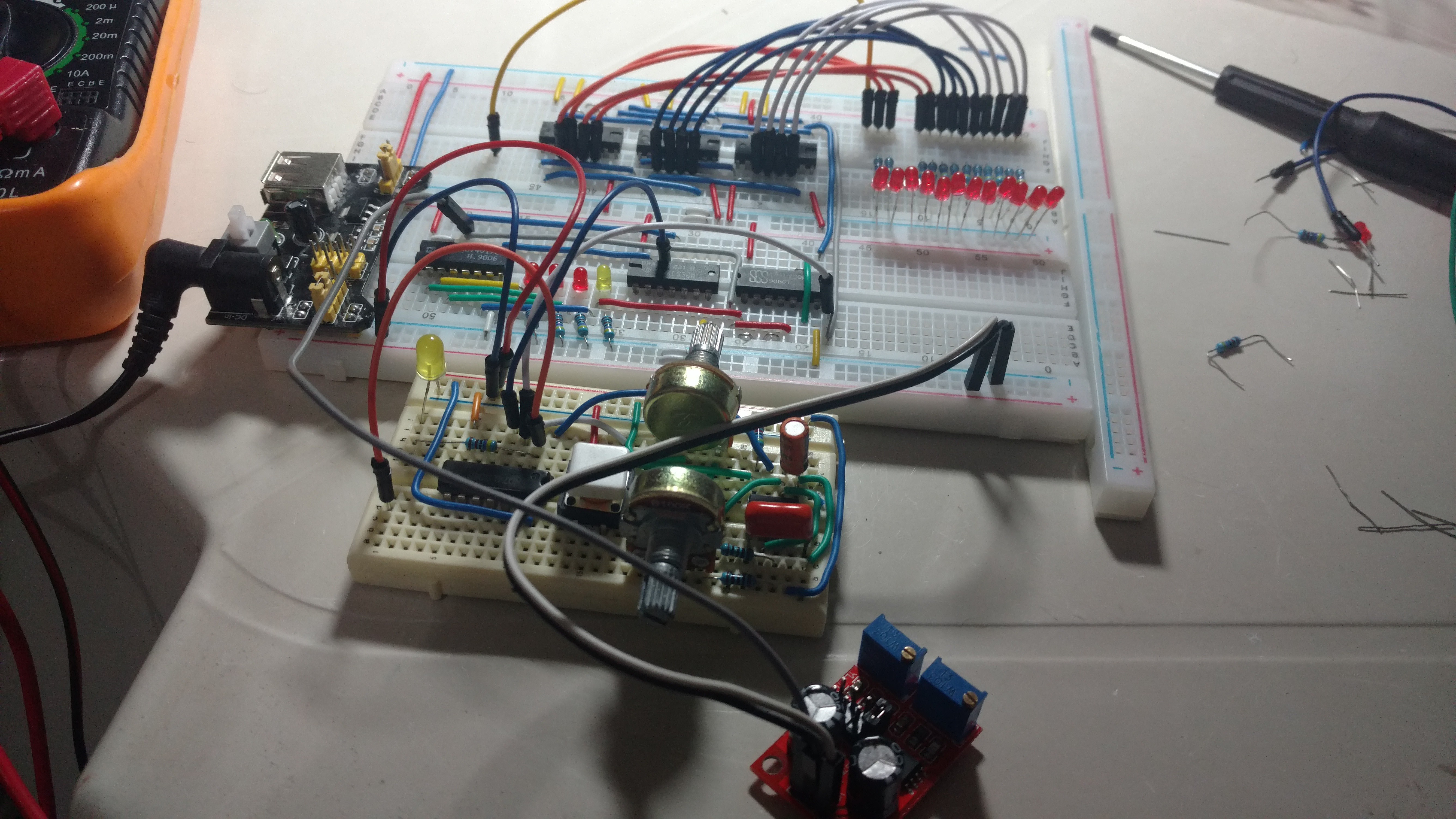
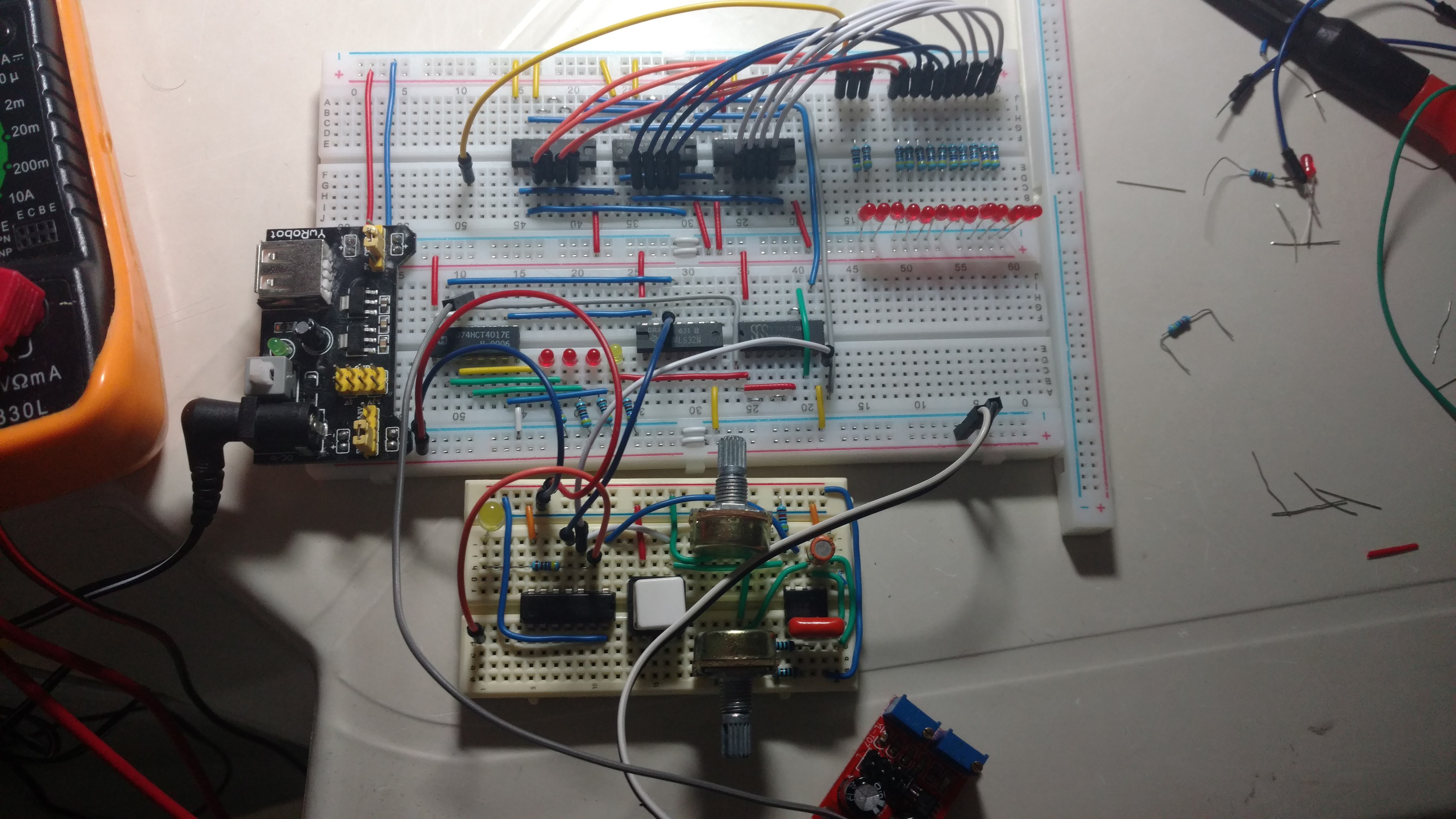
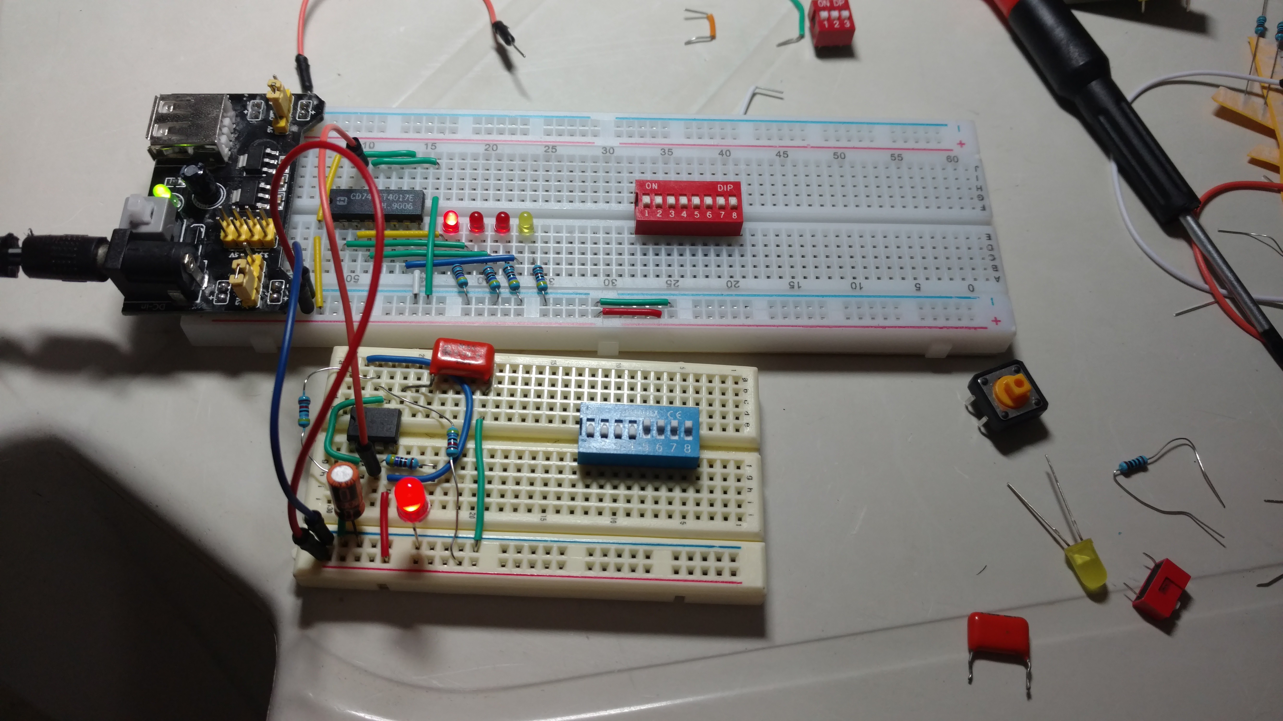
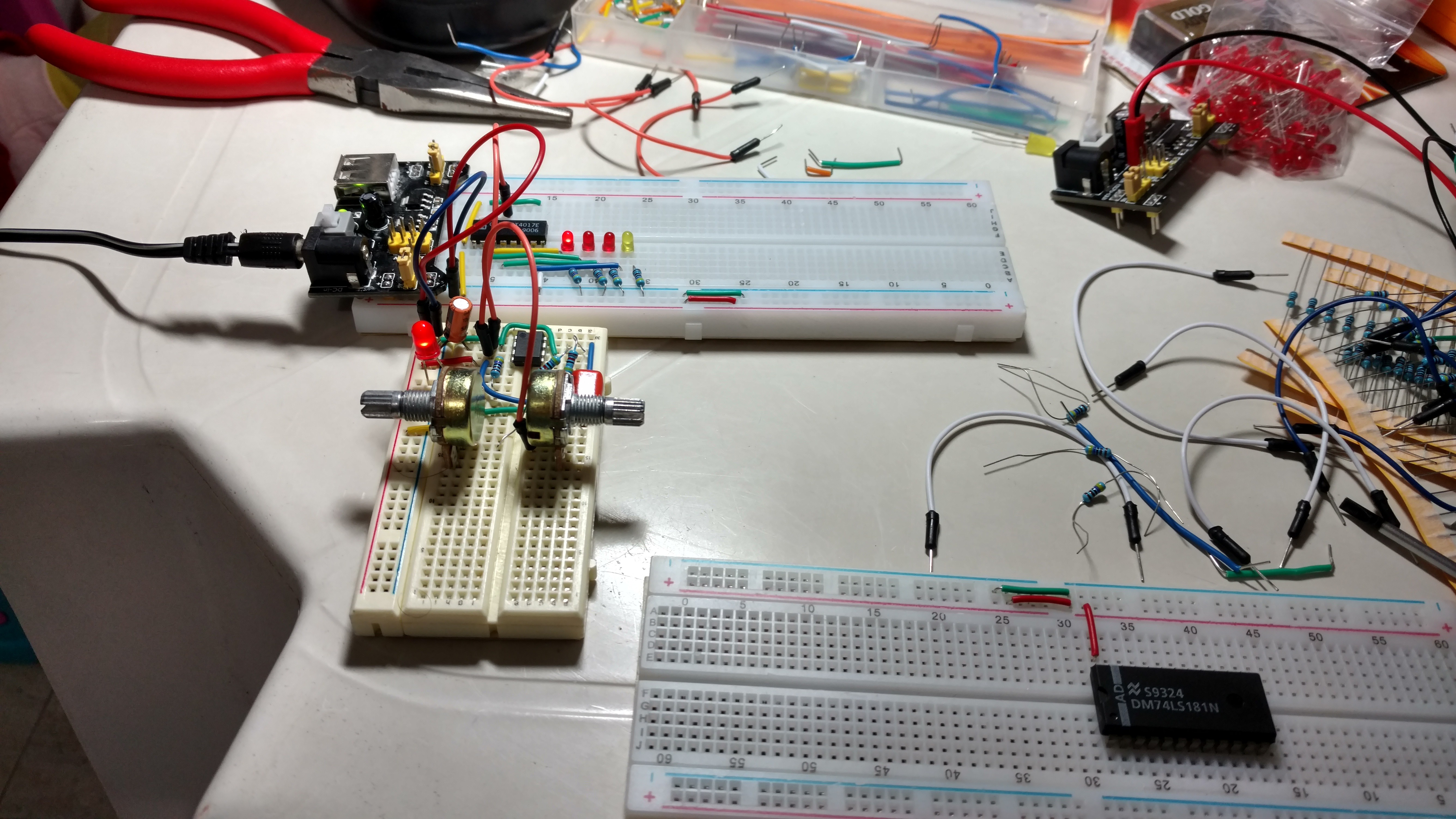
Finally I have something "real" to show:
I'm yet to receive many parts (thanks to the brazillian mail), but I could make the clock, and the 74HCT4017 to make the 4 cycles steps (Fetch 1 to 3, the red leds, and Execute, the yellow one).
It's a very small step, but I need to break the inertia.
Working with real hardware has it's peculiarities, It's very important to follow one of the XP principles, baby steps...
Between the lessons learned, never, NEVER keep inputs floting, the circuit behavior becomes imprevisible.
Thank you for reading.
![]()
![]()
JACA 1 & 2 Homebrew Computer
JACA - Just Another CPU Again Homebrew CPU, starting by a simple POC 4-bit CPU on circuit simulator soft. (done), then 8-bit (in progress)
 Registers logic very far from completed, with those ugly stickrs to help me remember what each wire is for.