 Mark Heywood
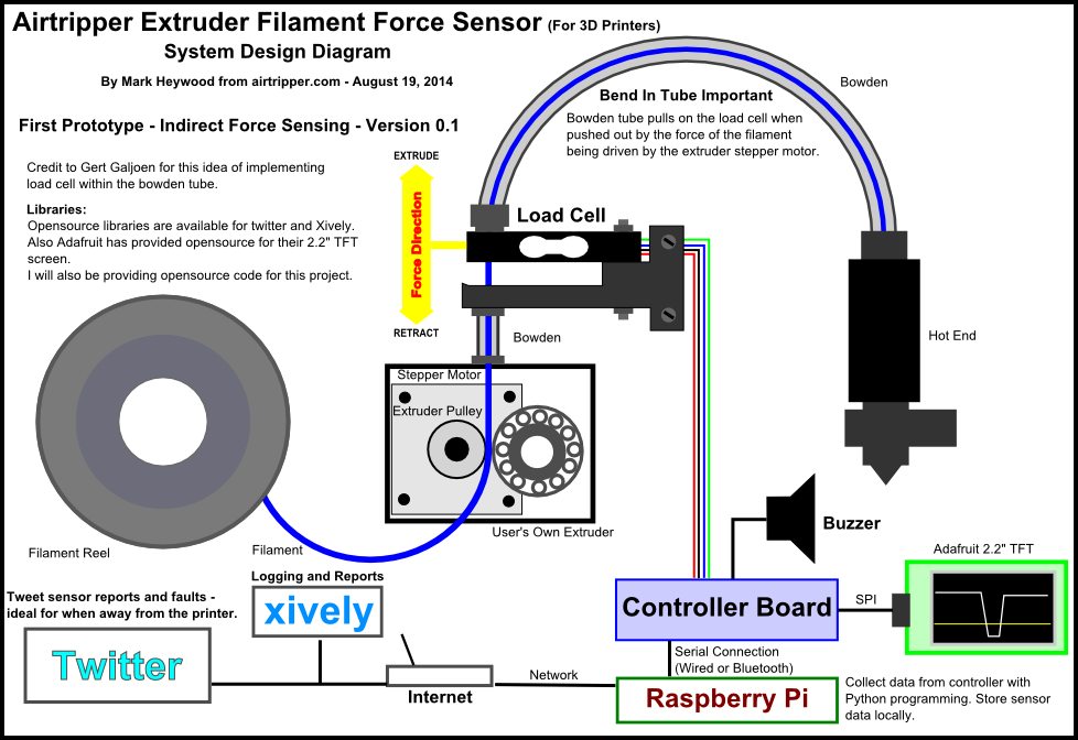
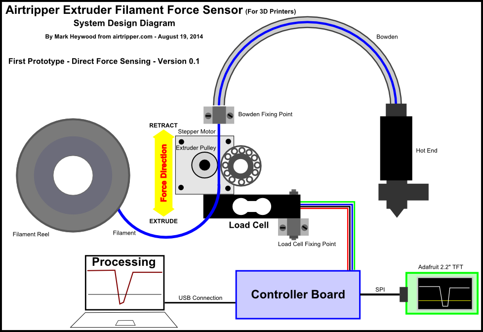
System Design Diagram
It is not necessary to complete the whole project in order to get some useful functionality. I currently use an Arduino Uno and Processing on the PC to occasionally check the extruder health on my 3d printer. I would just need to add a loud buzzer to have a short range alert system. I could set the buzzer to trigger when the force sensor measurements get too high, or too low when other conditions are met.
You can checkout this article for the basic circuit and source code: Arduino Load Cell Circuit & Sketch for Calibration Test
STEPS
The steps below are a summary of what needs to be done to get the project to completion. The steps will link to a more detailed explanation or instructions further down the details section of this page.
Step 1
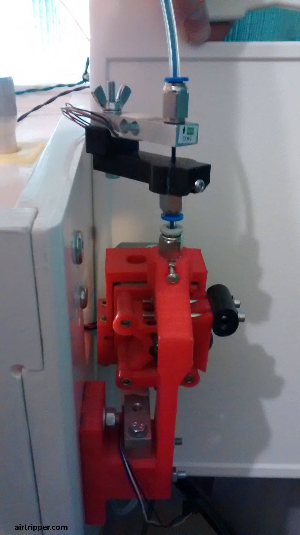
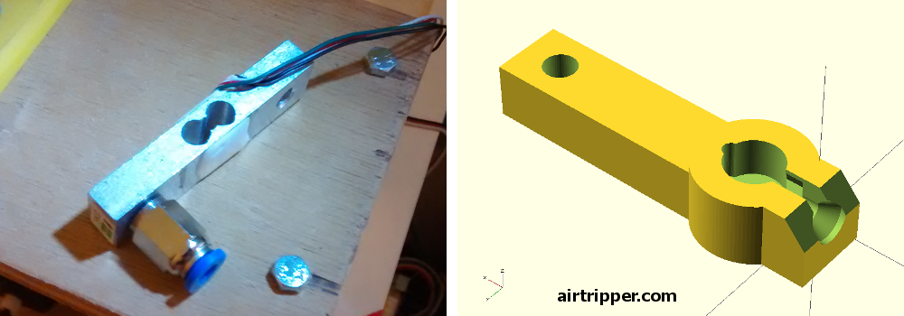
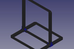
So, if you look at the system design diagram below, we first need to set up the load cell, that means we need to decide how the load cell will be attach to the 3d printer. Files to 3d printed part of the load cell bracket will be provided with this project, however, an additional bracket may need to be designed to complete the load cell fixture to the 3d printer chassis. Setting up the load cell will be detailed below.
Step 2
This where we look at adding some sort of controller to the load cell. Initially, you can go for the simple set up to start with as explained above, or you can get on board with the Teensy 3.1. More details to come on how and why the Teensy 3.1.
Step 3
We now look at setting up a Raspberry Pi, We'll assume that the Raspberry Pi is up and running by this point, but I'll recommend some links here to get the Raspberry Pi up and running to a level needed for this project
Step 4
Get the Raspberry Pi to accept data from the sensor controller. We could have the the Raspberry Pi collect data from more than one printer, so we need to think about an I.D. scheme for the printer.
Step 5
=======taking a short break
Load Cell Set Up
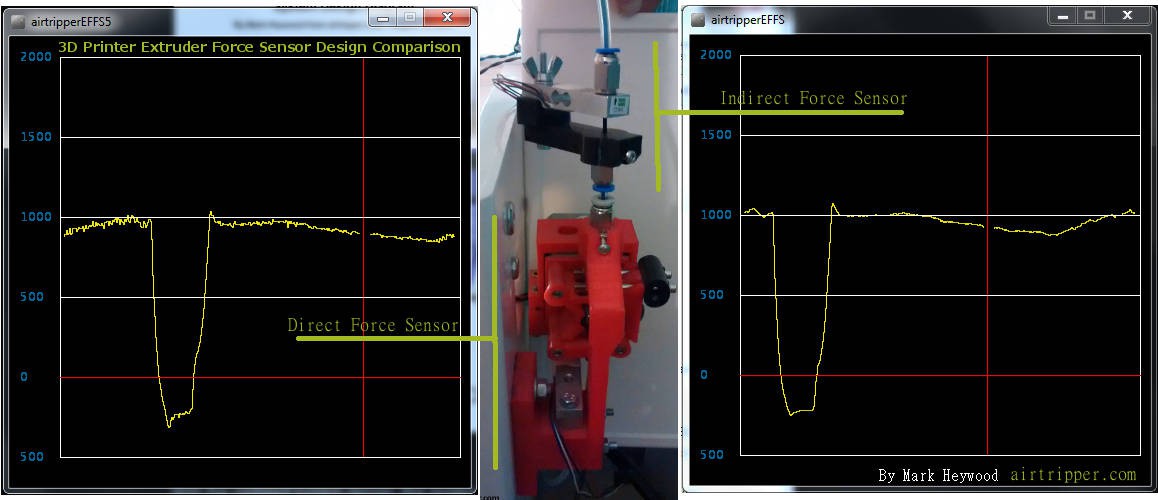
With the updated system design, this project should now be a lot more accessible to more 3d printer owners. The load cell for force sensing is now fitted within the bowden tube instead of being attached directly to the stepper motor. It should be noted though that it is important to have a bend in the extruder bowden tube in order to measure as much of the force as possible that is generated by the stepper motor. Test results of how much force is measured from the total force generated by the stepper motor will be detailed below when ready. So that the readings are consistent from the load cell, the bowden tube will need to be floating in air, electrical wires and such should not be cable tied to the bowden tube.
=====more to follow
Software
Libraries Required
Teensy 3.1:
Adafruit: adafruit/Adafruit_ILI9340
Adafruit-GFX-Library
Software License Agreement (BSD License)
Raspberry Pi:
Twitter: ryanmcgrath/twython
The MIT License
Xively: xively-python
Open Source, under the BSD 3-Clause license
=====remove or rework text below
Other Documentation
I've written a couple of articles that demonstrates how the filament force sensor behaves under different 3d printing conditions, and how it can be used to test extruder components:
3D Printer Extruder Filament Drive Gear Review & Benchmark
http://airtripper.com/1676/3d-printer-extruder-filament-drive-gear-review-benchmark/
Airtripper Extruder Filament Force Sensor – Introduction
http://airtripper.com/1338/airtripper-extruder-filament-force-sensor-introduction/
Nice Project! - Do I need this?
Mostly, for the average 3d printer user, you won't need a filament force sensor. However, if you have a 3d printer with a bowden extruder, you might at least need a little help in setting the right retraction distance.
Is the filament force sensor a worthy 3d printer add-on just for a small set-up issue? Probably not.
However, what is common with most 3d printer users, there are long print jobs, often taking many hours. I'm not going to admit to leaving the printer alone for a moment during those long print jobs, but on the occasion,...
Read more »

 Alonso Freire
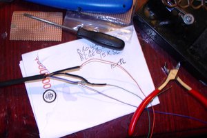
 Films4You
 Vedran
 CaptMcAllister