RaptorTech
-
PPM Output
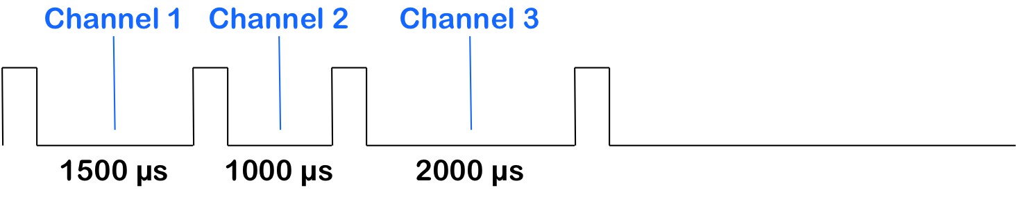
08/20/2014 at 18:23 • 0 commentsPPM stands for pulse position modulation. Many of you may be familiar with PWM (pulse width modulation) which is used for things like driving LEDs and servos. PPM is somewhat like PWM, except that it's the time between pulses that carries the data, and not the duration of the pulse itself.

PPM is typically used in the RC world for carrying information that would normally be carried by multiple PWM channels: specifically, the connection between a receiver and a satellite receiver, between a receiver and an autopilot/control board, or between a transmitter and a buddy-boxed transmitter.
In my case, Manucon will be emulating a buddy-boxed transmitter, so I needed to generate a PPM output to send information to the plane. This was simply a matter of scaling my roll, pitch, and throttle values to the range 1000-2000, and then sending out 100 microsecond pulses separated a delay corresponding to the scaled value for each channel.
This series of pulses is sent out every 20 milliseconds, just like a single pulse is sent out every 20 milliseconds when using PWM to control servos.
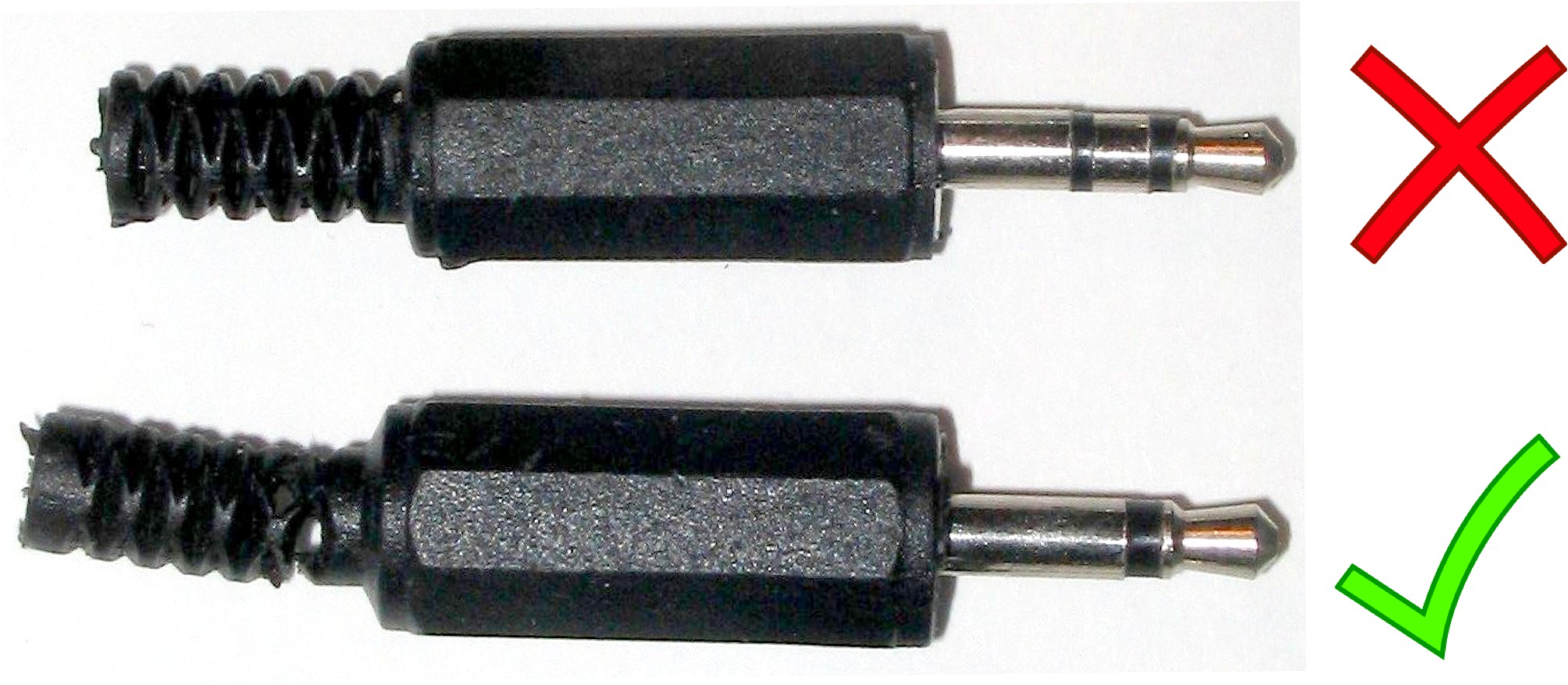
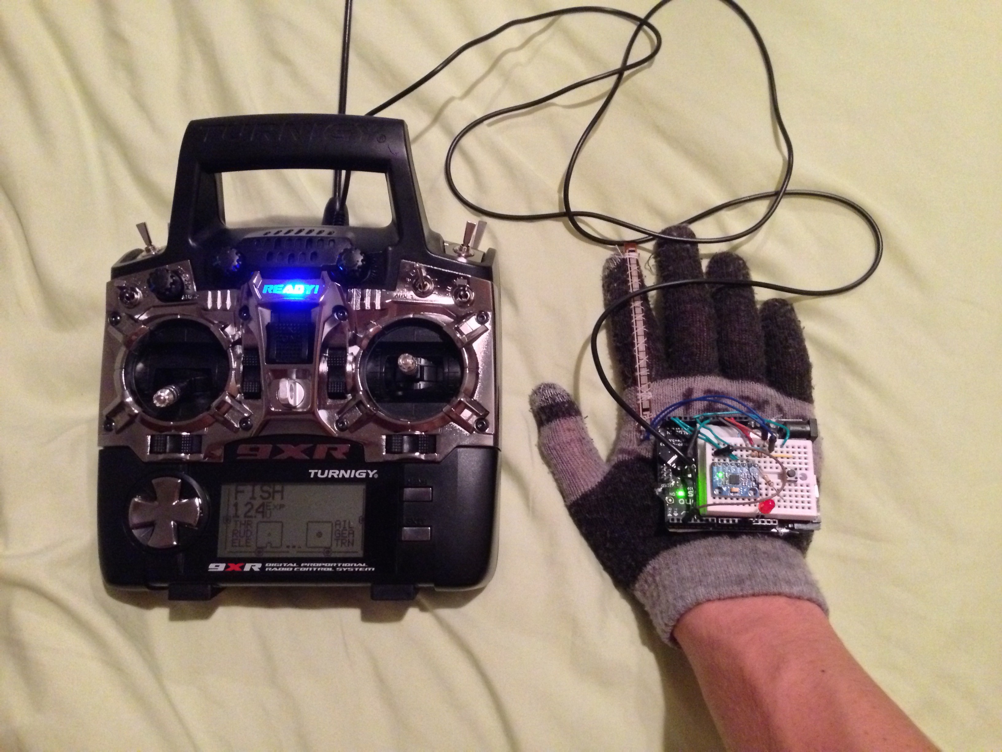
To carry this PPM data to the transmitter, I used the Spektrum/JR trainer port on my Turnigy 9XR. My home made trainer cable required a 3.5mm audio jack, of which I had plenty, but it is important to note that the audio jack should have a single channel (just ground and data).
The inside lead goes to whichever port on the OSSEP (or Arduino) you plan to use for PPM output, and the outside just goes to ground.
With Manucon and connected to my 9XR and the new PPM sketch on the OSSEP I hit the trainer switch on the transmitter to transfer control to the glove. Flexing the index finger controls throttle, rolling the hand controls ailerons, and pitching the hand control elevator. It worked on the first try!
The next day, I took my scratch built trainer plane, The Fish, and Manucon out to the field for some test flying.
-
Graphical Data Display
08/18/2014 at 03:21 • 0 commentsOnce I had sorted out my Arduino code, I decided I wanted to display the output data from the first prototype graphically.
Although I was already able to read text data about the orientation of the hand and the position of the flex sensor through the Arduino serial window, rapidly scrolling numbers proved nearly impossible to interpret. It was difficult to confirm that the data I was generating accurately reflected the position of the glove.
A graphical output would allow me to compare the motion of the glove to the motion of graphics on screen, which is much easier to do. It is also great for explaining to people how Manucon works, and demonstrating it's capabilities.
I decided to use Processing because it makes constructing graphics extremely easy.
To carry data from Manucon to my laptop, I simply used the OSSEPs USB port. Accessing the Serial data from within Processing was simply a matter of initializing the appropriate serial port and doing analysis on the incoming strings.
The incoming string is 3 numbers (between 0 and 1000) separated by the character 'x'. I can split the string apart at these x's to get the three data streams, and then use their values to format my graphical output on the screen.
Here is the result:
You may be noticing some glitching. This is a result of incorrectly formatted strings coming from the OSSEP Uno. The OSSEP is handling 3 input\/output streams (IMU, PPM to TX, and Serial) each of which requires somewhat precise timing. I decided to give precedence to the IMU and the PPM output streams because those are the ones responsible for controlling the plane. Therefor, timing on the Serial output can get messed up every once in a while, but it doesn't actually mean that the Manucon is sending the wrong information to the plane.
-
Arduino Code for the First Prototype
08/17/2014 at 20:34 • 0 commentsHardware completed, I started in on the software for the OSSEP Uno R3.
I knew the OSSEP was compatible with the Arduino IDE, so I plugged in the board and went to upload the blink sketch just as a test. Unfortunately the upload failed. Off to a good start already :)
A quick google search revealed that in order to use the OSSEP board, driver software was required. Even on a Mac! Can you believe it?!
Once I installed the driver software (available here), the blink sketch uploaded just fine and I got to the programming.
Reading data from the flex sensor was as simple as pulling the analog data from one of the analog input pins, and scaling the values from 0 to 1000 (I'll explain why I chose those numbers in a minute).
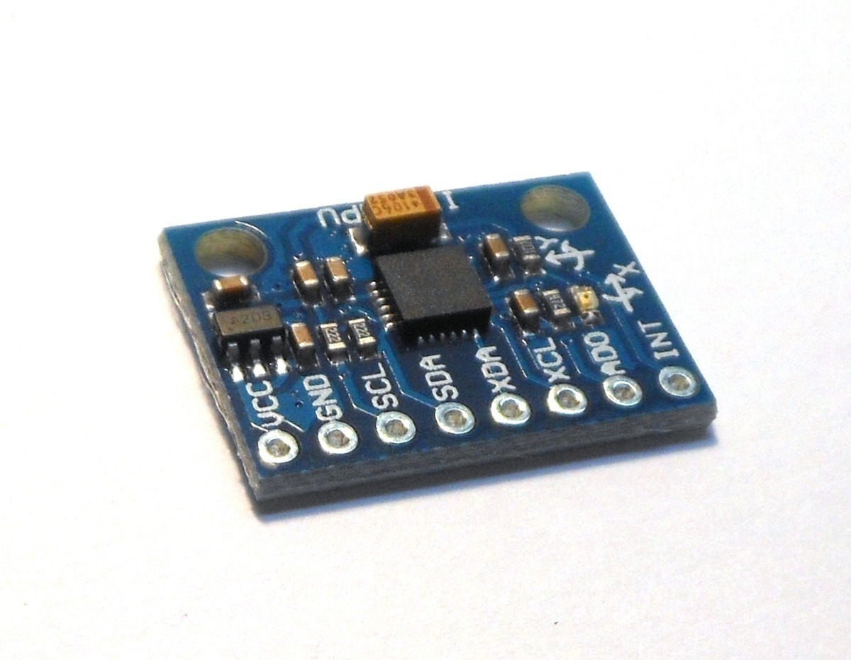
The MPU6050 is a little more complicated, but still not too bad.
MPU6050 is an I2C device, so I started by downloading and installing the I2Cdevlib library (on github). This library is a collection of many of the most common I2C devices, and makes interfacing these devices very easy.
Running the MPU6050 example sketch from i2cdevlib, I was easily able to display the raw data from the MPU6050's accelerometer, gyroscope, and thermometer. This was nice, but not terribly useful, because I needed the absolute orientation of the glove, not component accelerations.
After puzzling over how I might be able to get this information easily, I resigned myself to writing a Kalman filter, and settled in to start self educating on the topic. Kalman filters are very math intensive and require extensive tuning, so this code was shaping up to be more difficult that intended.
Then, it occured to me, the i2cdevlib library includes an example sketch to allow a 3D rectangle in Processing to mimic the position of the MPU6050. This means that somewhere in that code, there is information about the absolute orientation of the IMU. Although the serial output is not designed to be human readable because the data is passed straight to Processing, a few lines of code fixed that.
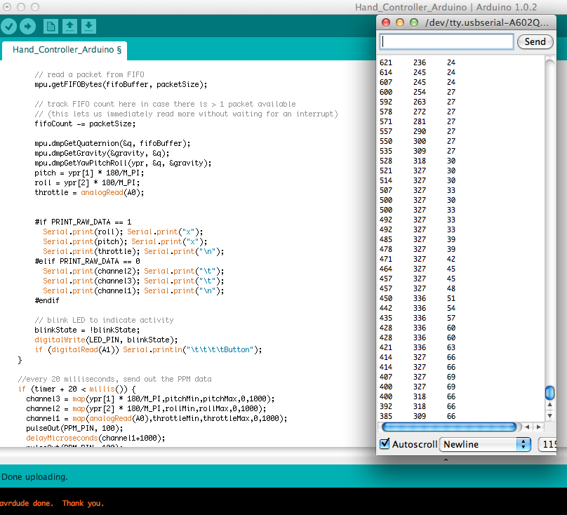
I commandeered that example sketch (and removed all the fluff), and printed all my data to the console.
Everything seemed to be working well, but there's only so much you can see from the rapidly scrolling numbers. -
Completed First Prototype
08/17/2014 at 04:49 • 0 commentsHardware
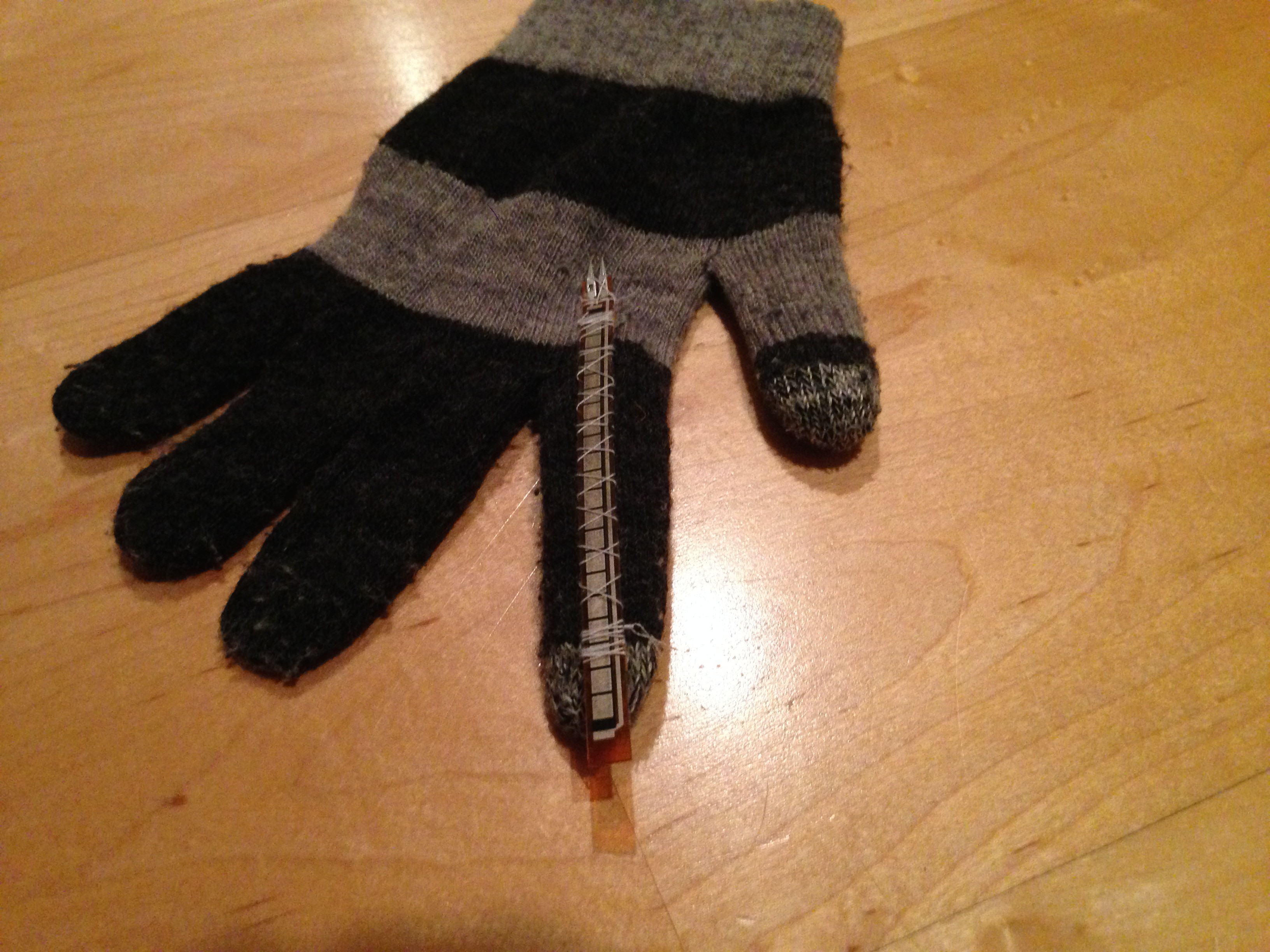
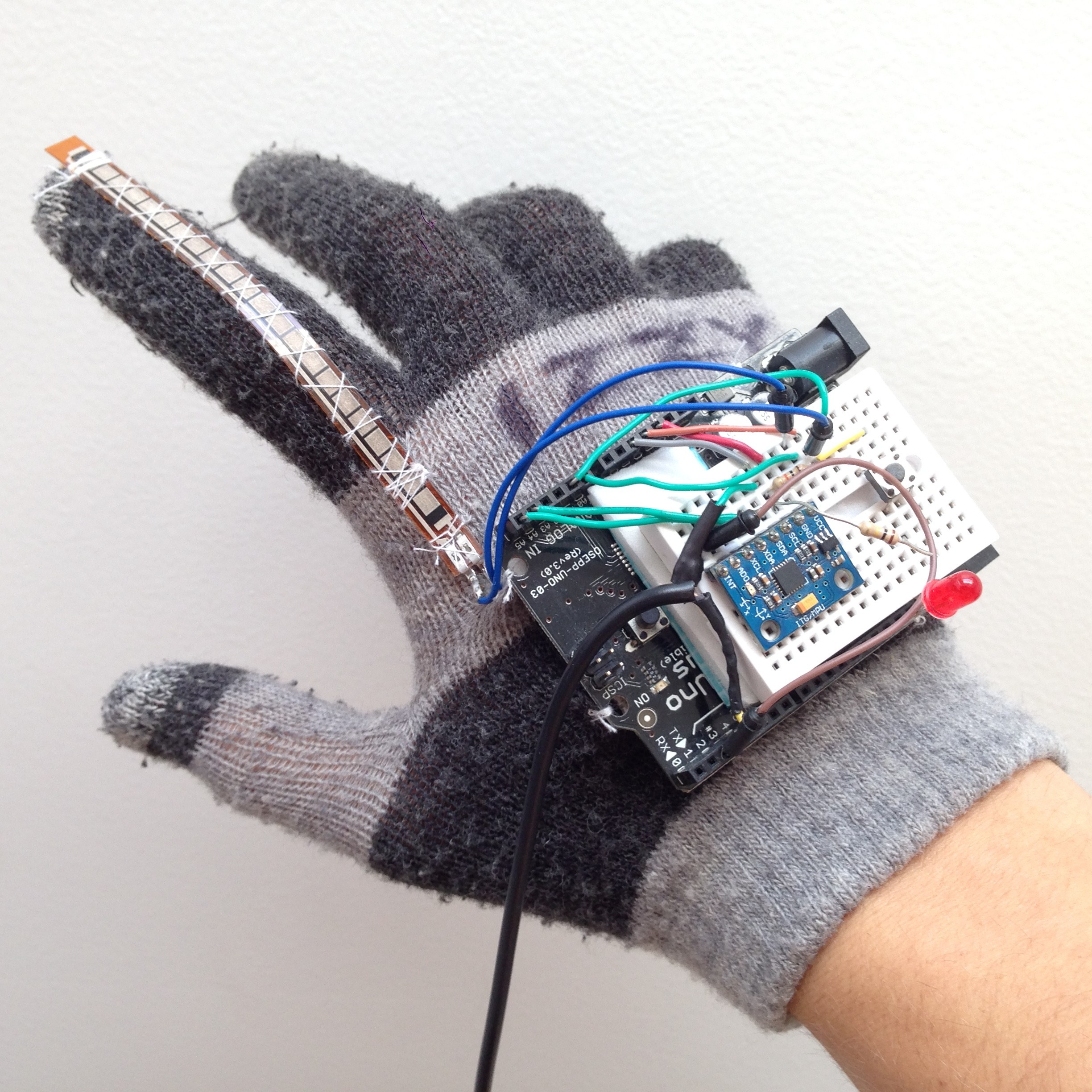
I began first by simply sewing the components I would need onto a glove. I went with a right hand glove because I found one that appeared to be missing it's partner. First, I sewed my flex sensor onto the index finger. This was really my first time working with wearable electronics, so the sewing probably took a bit longer than it should have ... oh well.
Next I sewed the OSSEP Uno R3 onto the back of the glove. I simply looped the thread through the mounding holes on the PCB. To protect the wearer from the sharp tips of the headers where they protrude below the PCB, I sandwiched a piece of foam below the board.
To simplify my wiring, I stuck a mini breadboard (10x17 holes) onto the microcontroller board between the rows of headers. Onto this breadboard, I added the MPU6050 6 axis IMU, and wired it up as an I2C device with power coming from the 3.3V pin.
After soldering some leads onto the flex resistor, I created a voltage divider using a a fixed 10KΩ and the flex resistor, and then connected the center of the voltage divider to an analog input pin. This circuit would allow me to calculate the resistance of the flex resistor, and therefor it's approximate flex.
I threw on a regular 5mm LED for status indication, and a standard push button for user input.
Finally, I found an old 3.5mm single-channel audio connector with a nice long wire and soldered on leads that would fit the breadboard. I connected the outside to ground and the center to a digital output pin on the OSEPP. This would allow me to connect the Manucon to a standard Spektrum/JR trainer port.
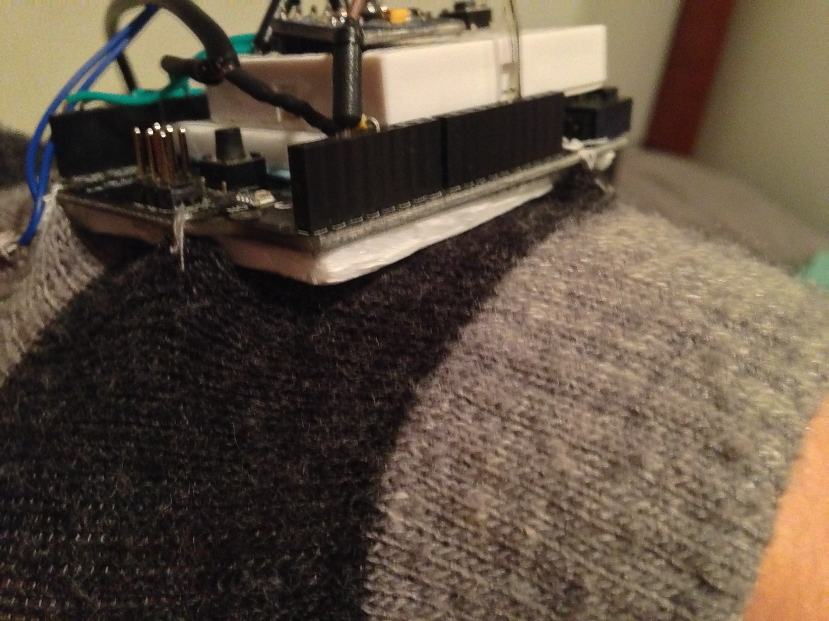
Here is the finished product:
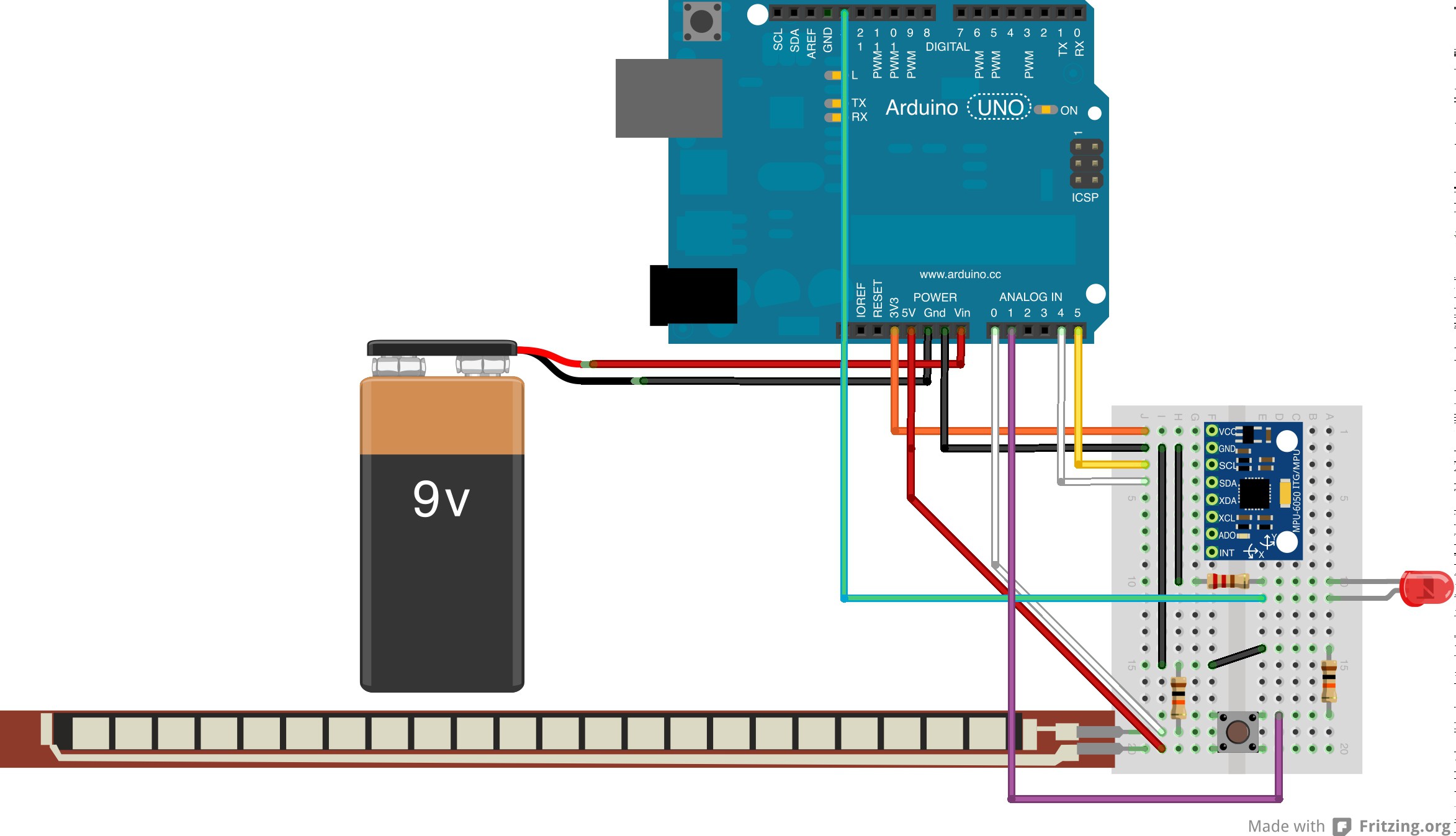
Breadboard view:
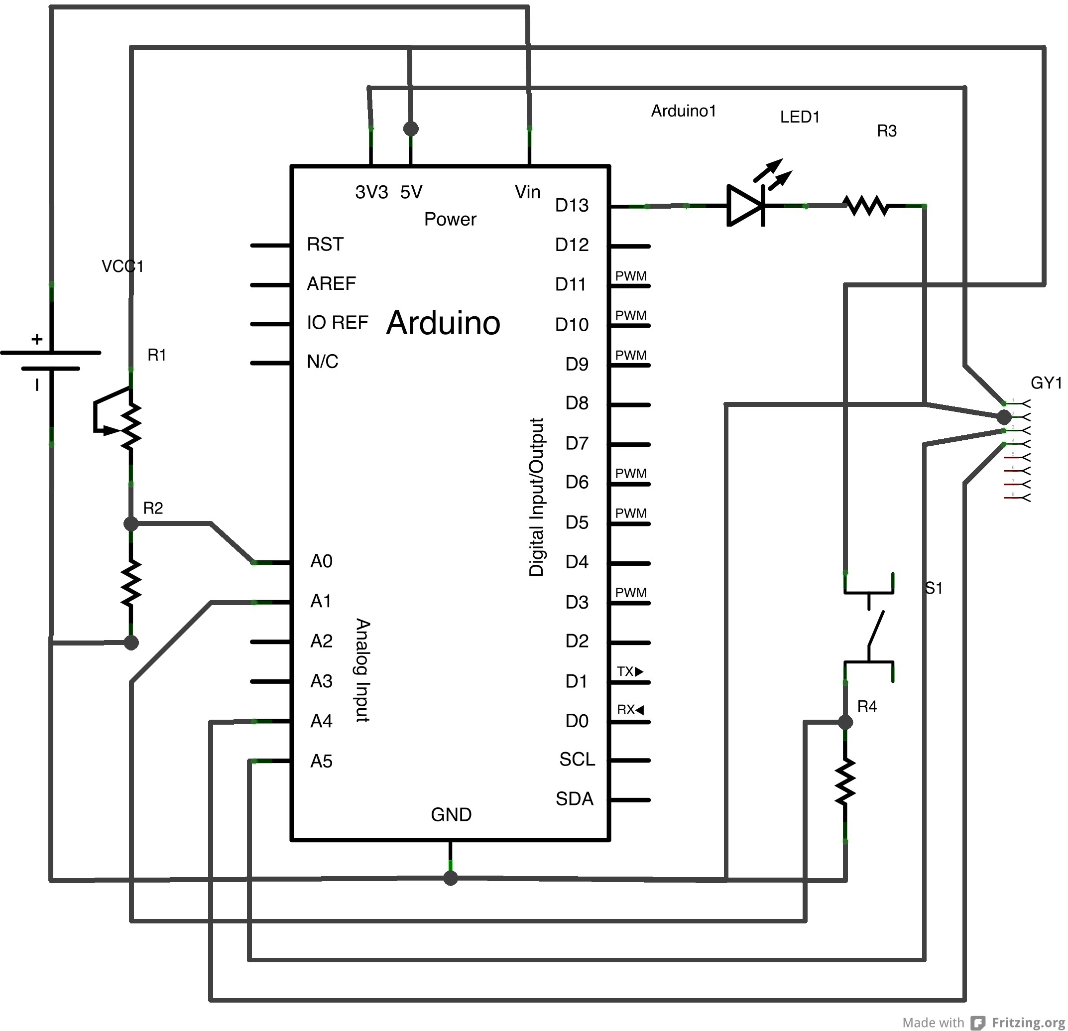
Schematic:
Manucon - A glove based controller
Use this sensor-loaded glove to precisely and intuitively control any model aircraft. Heck, control everything!