Eric Jacob
-
CNC Control Electronics
08/20/2014 at 16:50 • 0 commentsSchematic and Board Layout. I will link the actual EagleCAD files soon.
![]()
![]()
-
CNC Base Iterations
08/20/2014 at 16:48 • 0 commentsTo help illustrate the idea, we have produced a few drawings varying parameters.
![]()
![]()
-
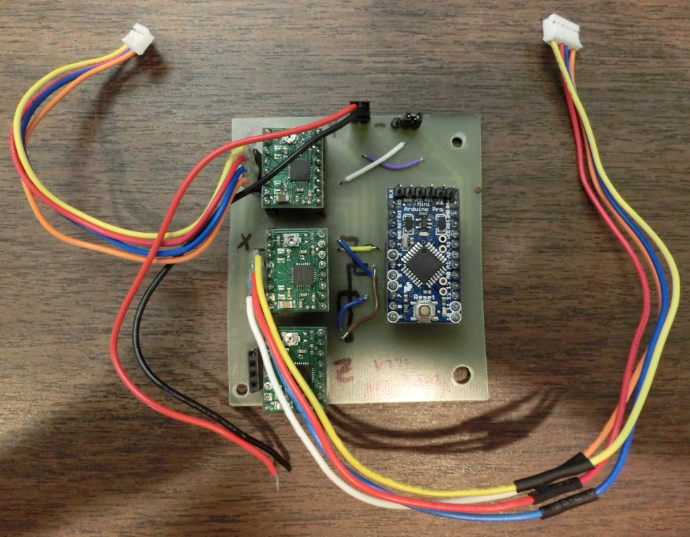
Control Electronics
08/20/2014 at 15:54 • 0 commentsThere are several options for transmitting/interpreting the gcode and controlling the stepper motors. The cheapest (but still quick and easy) way is to use pololu stepper motor controllers with an arduino board. This is sufficient for the smaller stepper motors (under 2A).
![]()
Some kind individuals have written grbl, https://github.com/grbl/grbl You can just use the Arduino IDE iterface to upload the code to the arduino. Then you'll want to use the universal gcode sender https://github.com/winder/Universal-G-Code-Sender to upload your gcode to the arduino. It all works great.
You are a little limited with the interface. If you want more control I would suggest moving to an actual CNC controller and Mach3. Of course this will cost more.
-
DXF Generation Code
08/20/2014 at 14:43 • 0 commentsdxf files can be a little tricky. In order to get around this I am going to use the python dxfwrite library. https://pypi.python.org/pypi/dxfwrite/
Python is free, so anyone will be able to use it. This library will allow us to create this code rather quickly as the dimensioning is progressing quickly. Initially we will focus on geometry, other features will be added as we go.
After the python code is complete we can look at creating a standalone generator (so you don't have to mess around getting python running if you don't want to) or making a web based application.
For now we intend to have the code create a dxf file. Gcode would be generated elsewhere as it is dependent upon your machine size and bit size. This is a secondary task that we will look into after the dxf generator is complete.
-
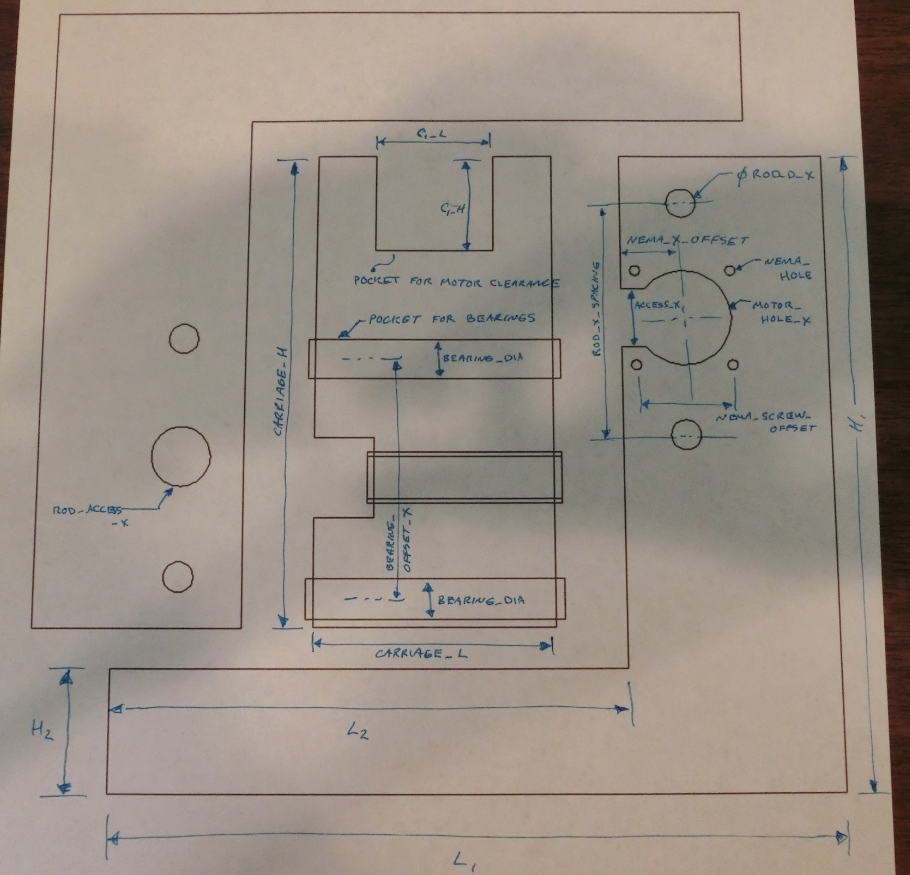
Parameterization
08/20/2014 at 14:35 • 0 commentsRight now the parameterized code is in the works. Here is an example of how the drawings are broken down into variables. These terms will then be defined in the code allowing for rapid generation of a new CNC base given the dimensions, motor size, bearing size, etc that we need.
Some of the dimensions will be dependent upon others.
![]()
-
Version 2.0 of the CNC
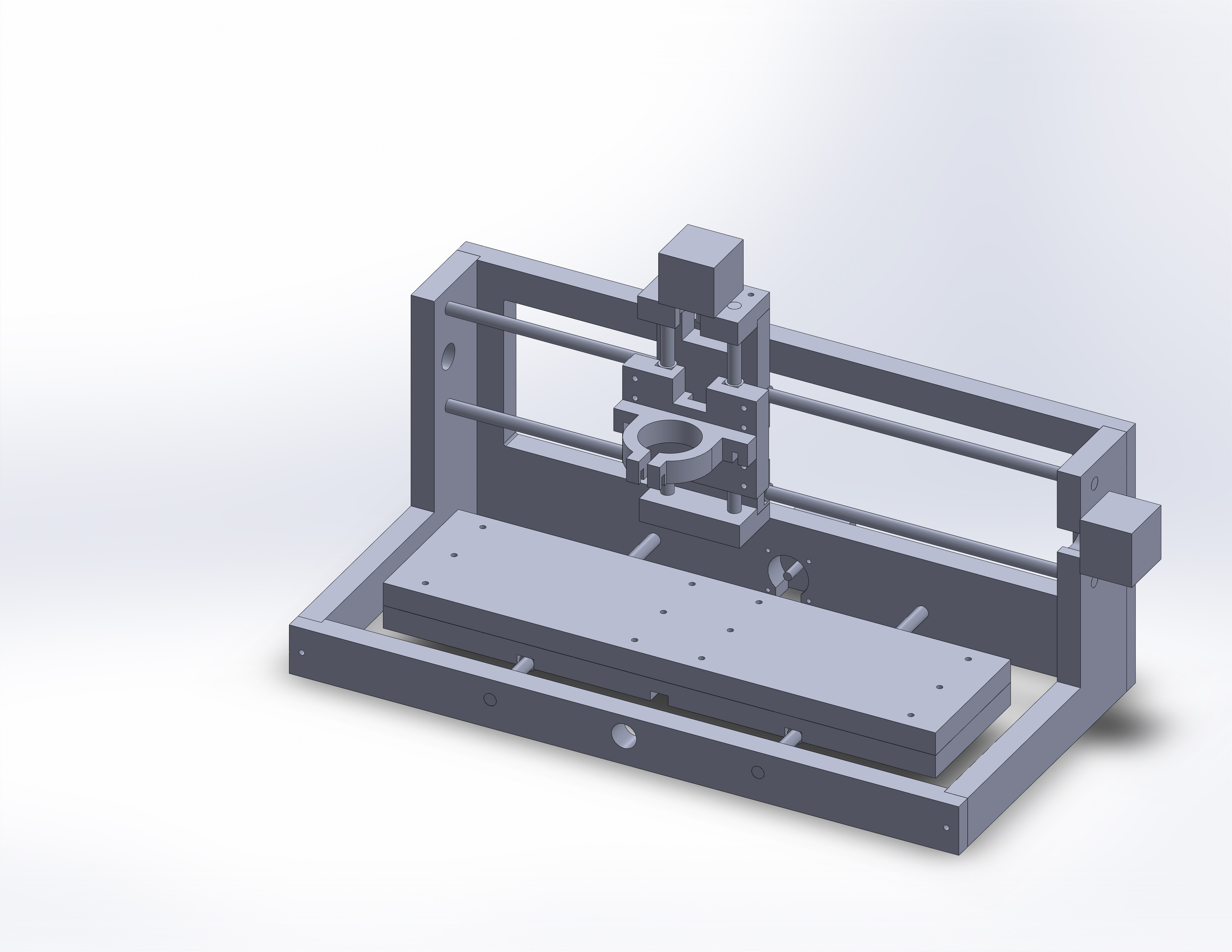
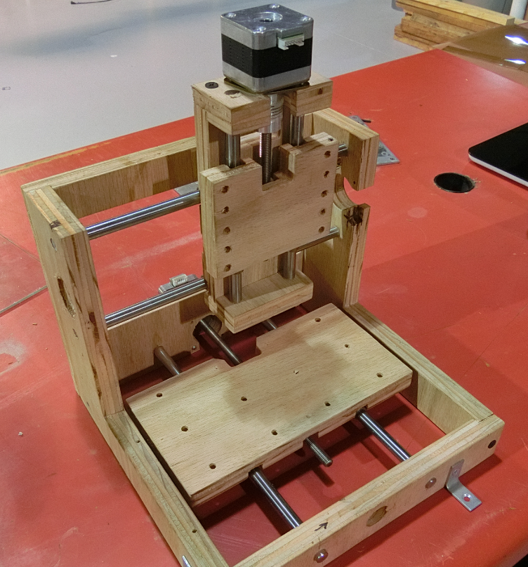
08/17/2014 at 16:23 • 0 commentsHere are some images of version 2.0 of the CNC. (I skipped version 1 as we have already surpassed it)
![]()
On the front you can see the platform and carriage. We've integrated multiple pre-drilled holes for easy mounting of spindles or clamps.
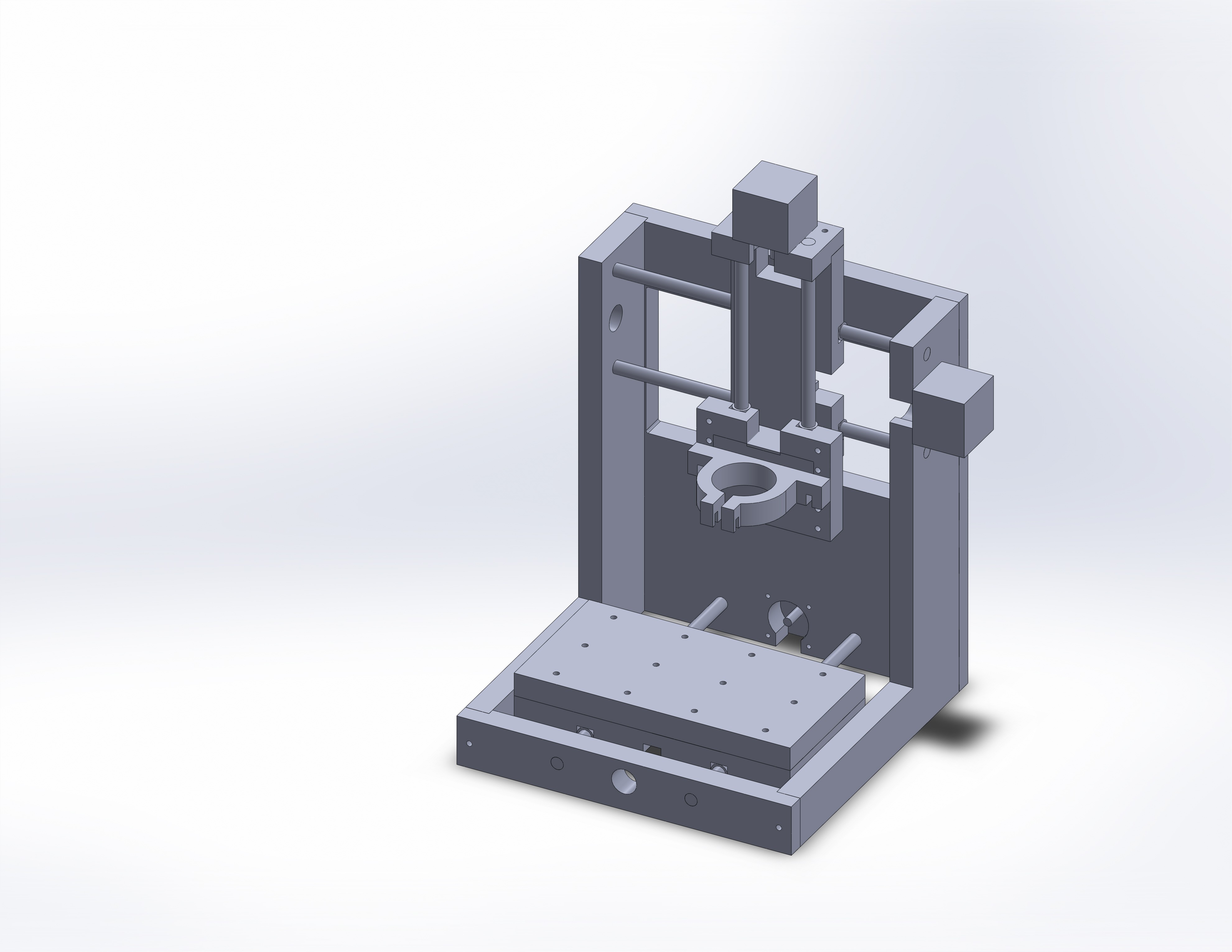
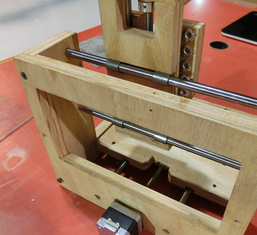
The image of the back shows the linear slides. Here we have elected to use precision rods with bronze bushings. Grooves are cut into the plywood and the bearings snap into place. Glue can be used to further secure the stage. Allowing the stages to snap into place make assembly and alignment much easier.
![]()
You can see a motor mounted on the bottom. On of the base plates was milled out of the back plate producing an access window for easier maintenance.
If you look closely on the upper right of the image you can see that we have notched the back plate. This makes everything line up nicely. Some of these features would not be used in the non-CNC version as they would be difficult to produce.
This is the second version. The first version was based on the Mantis and we have made improvements beyond that. (http://makeyourbot.wikidot.com/mantis9-1) This is version 2. We keep a running list of improvements/features/enhancements that we would like to add and integrate them the next time we need a CNC base.
Now the mechanics are working pretty well, our next effort is to parameterize the CNC base so that we can quickly make any size machine.
Inexpensive Multipurpose Parametric CNC Base
We've taken a simple CNC base and are writing a python code that can generate CAD drawings based on your needs. ~$100 build.