Hugh Darrow
-
Major Changes, Bug fixes, Improvements, Features, etc
07/14/2016 at 07:59 • 0 commentsIts been a while since I last updated my project, but with some time every now and then I've made over the course of the time some pretty decent improvements I think. Here's just a simple overview of some of the changes, and the dates as I went through them. I also switched the SIM module to the adafruit fona 800L, and bought a seperate SIM card from Ting (pay as you use), so I can have my regular phone, and call/text back and forth for testing. The new module is much smaller and easier to take to scale when the time comes, also including bluetooth. See end of this log to see current set of features I've documented and implemented. Some features are coded, however they just came to me, and I didn't document them. If you notice some, please let me know. All the new files are uploaded on Github and ready for action.
P.S. I'm thinking I want to design a better GUI, with a decent API structure, and I'm thinking I want the screen to be one big object, and each thing it a different object. However, I know of no books on the concept or idea of GUI programming at the hardware level for API. If someone has thoughts or somewhere I can go, please tell me.Project Log Update
==================
Simplified code tx and ty values, as well as position values
Simplified the time placement values
Added time display to passcode screen and reformated the display of time
1/5/2016
Added transitor based power control of SIM module
Removed psuedo-boot sequence
1/6/2016
Added Ignore Call feature
12 am is now displayed correctly instead of 00 am
Date display comma position corrected
1/7/2016
Clock is now set to refresh at power up regardless of current power of SIM module
Added Answered Screen to include call duration
Fixed "Call Ended" from overlapping clock and numpad
Fixed "Wrong Passcode" from overlapping clock
Fixed caller side disconnect to respond on client side correctly
Code Speed Ups
1/18/2016
Removed or commented out unused variables
corrected code
created new folder for easy usage, (auto-import libraries)
Renamed Files
4/2/2016
Added Screen dimining function just before display sleep
7/13/2016
Libraries Updated
Call Ended Fixed
Fixed Debouncing Issue and improved touch algorithum
Added Display for Battery Level
Removed repeative code
Text Screen and text message functions bug fixes
Clear Notifications when selected (still needs intelligence of when read)
SMS Send Screen formatted correctly, along with time
Current Feature Set:
-------------------------------Place calls, receive calls, hang up calls, ignore calls
Dialing numbers and displayed on-screen
In call DTMF Tones
Read incoming data from SIM Module, and provide functions and executions based on data
Display prompt for incoming texts
Display time in a human readable format including AM/PM and updated at 00 seconds
Seperate and Defined Screens with functions and touch values per screen (ie. Phone vs SMS)
Read individual texts defined/sorted by index
Delete SMS
Caller ID
Display Missed Calls
Passcode along with 5 second lapse before start
Notification LEDs
Display has timeout sleep based on Touch Inactivity
Automatic Power On for SIM Module
Screen Darkening clockTime before Sleep mode -
Wrong yet again.....sigh
11/20/2014 at 23:20 • 0 commentsSo I was wrong again on the implementation of the functions for scanning flip for horizontal and vertical, and the text Rotate. I was ^= for both the true and false statements, which didn't work out well with the logic. Here's the logic needed, if 0 and false, remain false, if 0 and true, change to 1, if 1 and true, remain 1, if 1 and false change to 0. With my implementation it was just a switch statement, whether you used true or false, whatever is there will get a XOR of 1 or 0 depending on whether you said true or false, thereby switching no matter what. In the end the result I currently have and seems to be working with no bugs, for true use temp |=, which flips 0 to 1, but leaves 1 if true is used elsewhere, and for false, temp &= ~ which checks if 1 flip to 0, if 0 leave 0, where the ~ means to flip or NOT. Here is an example of the scanV_flip function
if (V_scan) {
writeCommand(0x20);
uint8_t temp = readData();
temp |= 4;
writeData(temp);
}
else {
writeCommand(0x20);
uint8_t temp = readData();
temp &= ~4;
writeData(temp);
}Currently all the functions are working as intended, but if you find otherwise just let me know and I'll do some debugging. Hopefully this is the last revision of this particular code.
-
Bitwise Operations
11/18/2014 at 00:35 • 0 commentsSo interestingly when I went to go write the code for the sending screen for SMS, the screen scanning functions didn't work. After doing a formal research I found that in the code when it reads the registers from the the ra8875 driver, it stores it as uint8_t or a 8-bit character or char. When I wrote the code
writeReg(0x20, ((1 << 4)));
I thought I was saying at bit 4 flip to one, in fact this isn't the case. The << operator actually means shift, so I was shifting a 1 into bit 4 from bit (3 or 4), still haven't fully learned the logic and syntax yet, when what I wanted was just to flip the 4th bit, then for the other functions the 3rd bit and/or the 2nd bit, depending on the functions. This is where the bitwise operators come into play. The basic operators are ^= meaning XOR, &= meaning AND and |= meaning OR. Now here's how they work. For all scenarios we'll be using 8 bits. For XOR lets say you read the number 106 and store it in the variable uint8_t. If you were to read that back it would show 106. But what we need to be looking at is the binary, for this you can do it by hand, or with a calculator, I used which one in the OS I was at the time, and I can confirm both Windows and Linux calculators have programmer mode, albeit I prefer the Linux version, straighter to the point. So the number 106 in binary is 0110 1010. If we were to use the the binary sequence 1001 0101 with the operator XOR the result is as follows
0110 1010
1001 0101 XOR
-------------
1111 1111 result
So if you follow the logic, everything is flipped so long as there isn't the same bit in the same sequence here's another couple examples.0110 1010
1111 0101 XOR
-------------
1001 1111 result1001 1111
1001 0101 XOR
-------------
0000 1010 result
So its pretty simple logic, the and and or operators are identical to there normal counter parts, if using AND and both bits in each sequence is a 1, then its a 1, if both are 0, then its a 0. If using OR then only one of the bits in the same sequence needs to be a one for it to be a one. Examples1001 1111
1001 0101 AND
-------------
1001 0101 result1001 0101
1111 1010 OR
-------------
1111 1111 resultThe next step is to actually use them, and do real operations. In the cpp file of the ra8875 library, the function scanV is as follows
void Adafruit_RA8875::scanV_flip(boolean V_scan)
{
if (V_scan) {
writeCommand(0x20);
uint8_t temp = readData();
temp ^= 2;
writeData(temp);
}
else {
writeCommand(0x20);
uint8_t temp = readData();
temp ^= 2;
writeData(temp);
}
}
Now as you can see I've already made the neccesary changes to reflect the operations I wanted, but lets start from scratch. The first part says define a new function called scanV_flip, accept a boolean input, and create a temporary (boolean) variable named V_scan. Next is to check that new temp variable V_scan, and if true, then perform writeCommand(0x20). This is what allows us to tell the driver, hey we are referring to your register address in hex 0x20. Then we create a new variable 8 bits long with uint8_t temp, and initialize it to readData() or the 8-bit sequence located at Register address 0x20. We now have some unknown sequence, that right now we really don't care. What we do want is is to flip the #1 bit in the sequence, like this XXXX X_XX. So if its a zero, make it a 1, if its a 1, make it a 0. For this operation I decided to use the XOR operator for the logic stated above. Now the number 2 is used because when we represent the number 2 in binary (using 8-bits) 0000 0010. So now matter whats int the rest of the sequence we'll only flip the 2nd bit. Lets say we wanted to flip the 3rd bit, XXXX _XXX. We would use the number 4. This is because each bit in the sequence is really just 2 ^ of that bit. So bit 0 is XXXX XXX_ and is equal to 1 (2^0), and bit 7 is _XXX XXXX and is equal to 128 (2^7). So we can write any sequence of binary in any number want by just knowing the bit we want to operate. Another example its lets say we wanted to flip the 3rd, 4th, and 7th bit, again I would use the XOR operator and write
temp ^= 152;
Because 1001 1000, with the bits 3, 4 and 7 flipped to one. So if we had the sequence read from the Register address 0x20 read out 44, or 0010 1100. Then after the XOR operator using temp ^= 152; the same address would read, 180 or 1011 0100 in binary.
I've corrected my mistake in the libraries and uploaded the new versions to Github. This was a good learning experience and a real wtf is going on. Especially when I would use just one function and it would work, but not two, and not if the same one was used again? Took awhile but that's the result. Good old fashioned learning by failure, after failure, and the desire to get it right. -
Much, much, much more Features (Getting COOL)
11/12/2014 at 01:09 • 1 commentSo a couple weeks ago I got sick and although I hated it, it did give me a lot of free time to program, so this next roll out it a pretty big one. Tons of code enhancements and optimizations, including new functions, but most of all the phone is looking awesome. There is a new passcode lock, and dedicated screen, and new dedicated screens for home, phone, and sms. I also implemented a power led, new message led, and missed call led, along with a button to turn the display on and off, with a lock at each push, an answer screen (still don't know how.tf ignore works on modern phones), and the display reacts to incoming data from the GPRS. Suffice it to say, lots of cool stuff, where the only missing is a send SMS screen, which I'm currently working on, and then its fully portable and ready to go, abliet low memory for SMS, but that'll come as a quick second thing to do.
I've also done some preliminary power tests, and the GPRS shield uses 7mA with the SIM900 powered off, 17mA powered up, and 7mA when in sleep mode (AT+CSCLK=2, any data on UART will wake it, just make sure to add some garbage bytes at the head stream), while in sleep mode it periodically wakes up to check the network. The display driver uses 52mA, and the display uses 144mA while on. I'm also working on sleep modes and reading datasheets on the SAM chip to figure out if there is any efficiency I can pull from it, otherwise I'm using >240mA with display on and >140mA with the display off, which with a current/modern lipo battery that would give me 22hours stand by time, and 12 hours usage, which I think sucks. I'd like to double those numbers if possible, and get quite literally the lowest possible power consumption, while still workable. Which is why I'll be playing around with both the sleep modes on the SIM900, and the atmel SAM, and possibly completely cut power to the display driver with a transistor, and a light sensor to shut off display when the phone is up to a persons face. All in the hopes of droping the power usage down to just a few mA, say like 10, giving me a 12 day standby time, and 30-40mA during call, giving a 77 hours talk time, which sounds a lot better to me. And just for you smart readers out there, I'm using mA right now just because its easier to estimate and judge, in the future I'll come back with exact watts.
As for now have fun, and hack away, its really starting to look cool, and act well I think.
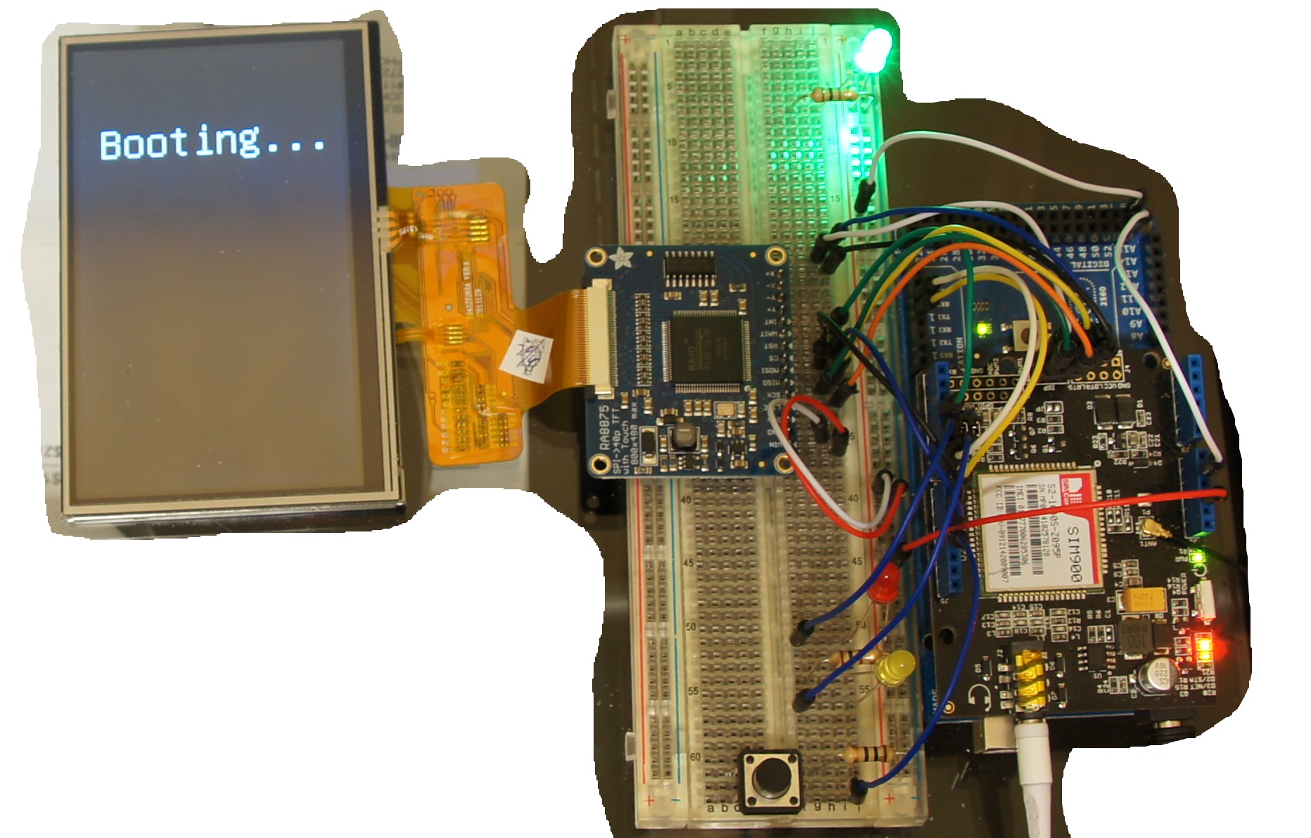
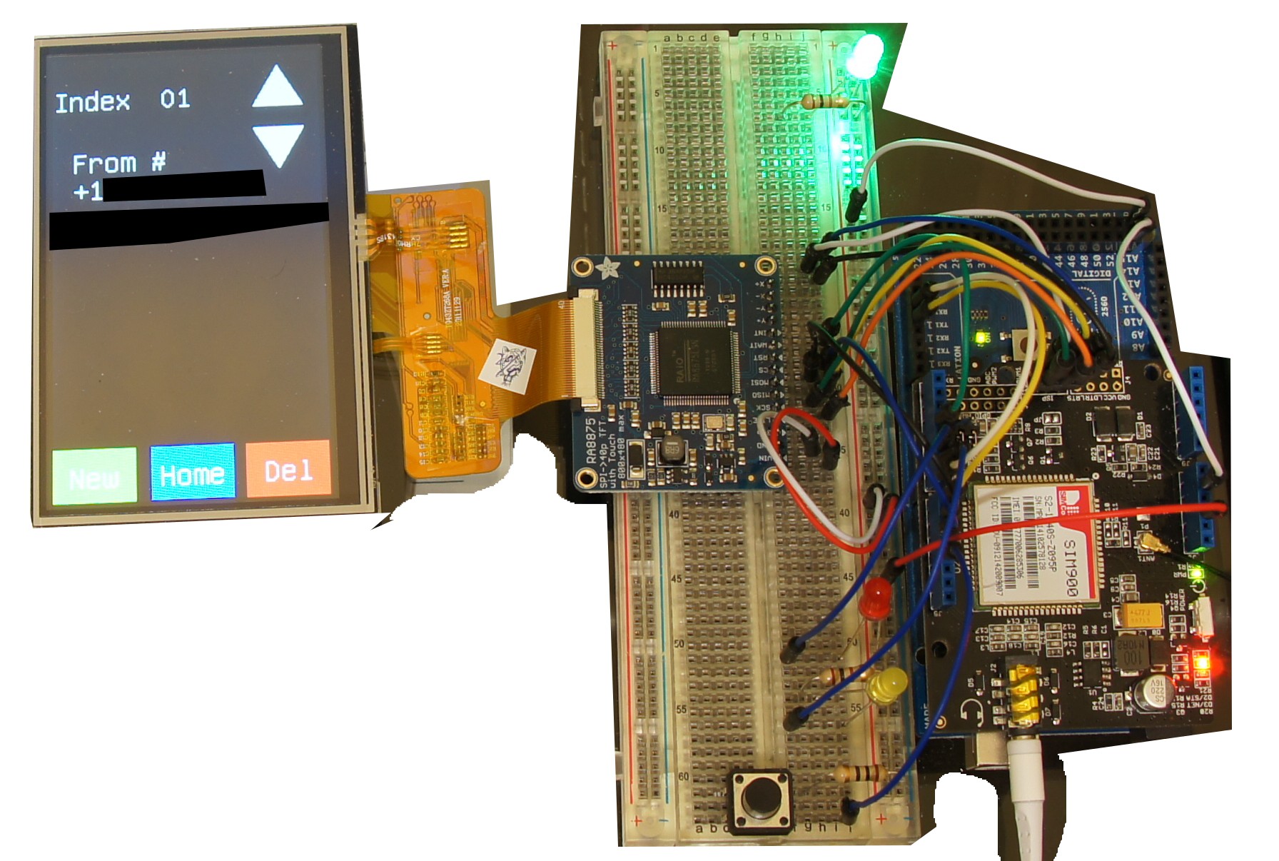
PS. I fried my SAM chip and had to order a new one from mouser for $14, so if your following along, don't accidently touch any power leads to exposed pins or blam, you'll get the same. And if you need to check the chip, while everything is unplugged, do a continuity test from the GND pin to any of the voltage pins, if its a yes, bye bye chip. To replace the chip cheaply, which I currently don't have enough money for a hot-air rework station, I just used a frying pan on my stove top, and used my non-contact thermometer to guage the stove-top setting, shooting for around 240-280C. Be prepared for small melts of the plastic, and little smoke from the bottom silkscreen.Pictures using my MEGA for reasons stated above (had to use 2400 baud instead of 38400)
===================================BOOT SCREEN==================================
![]()
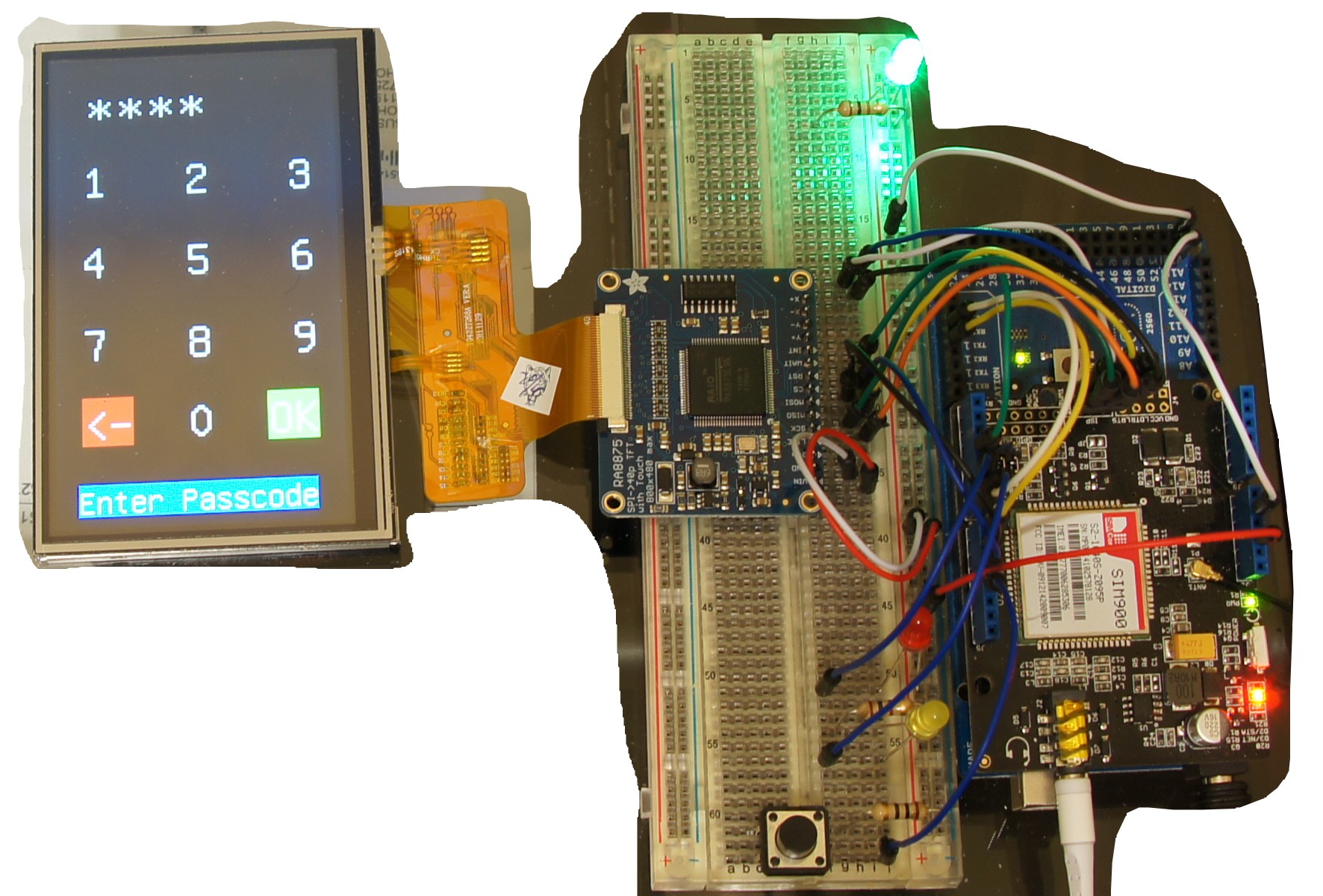
================================PASSCODE SCREEN================================
![]()
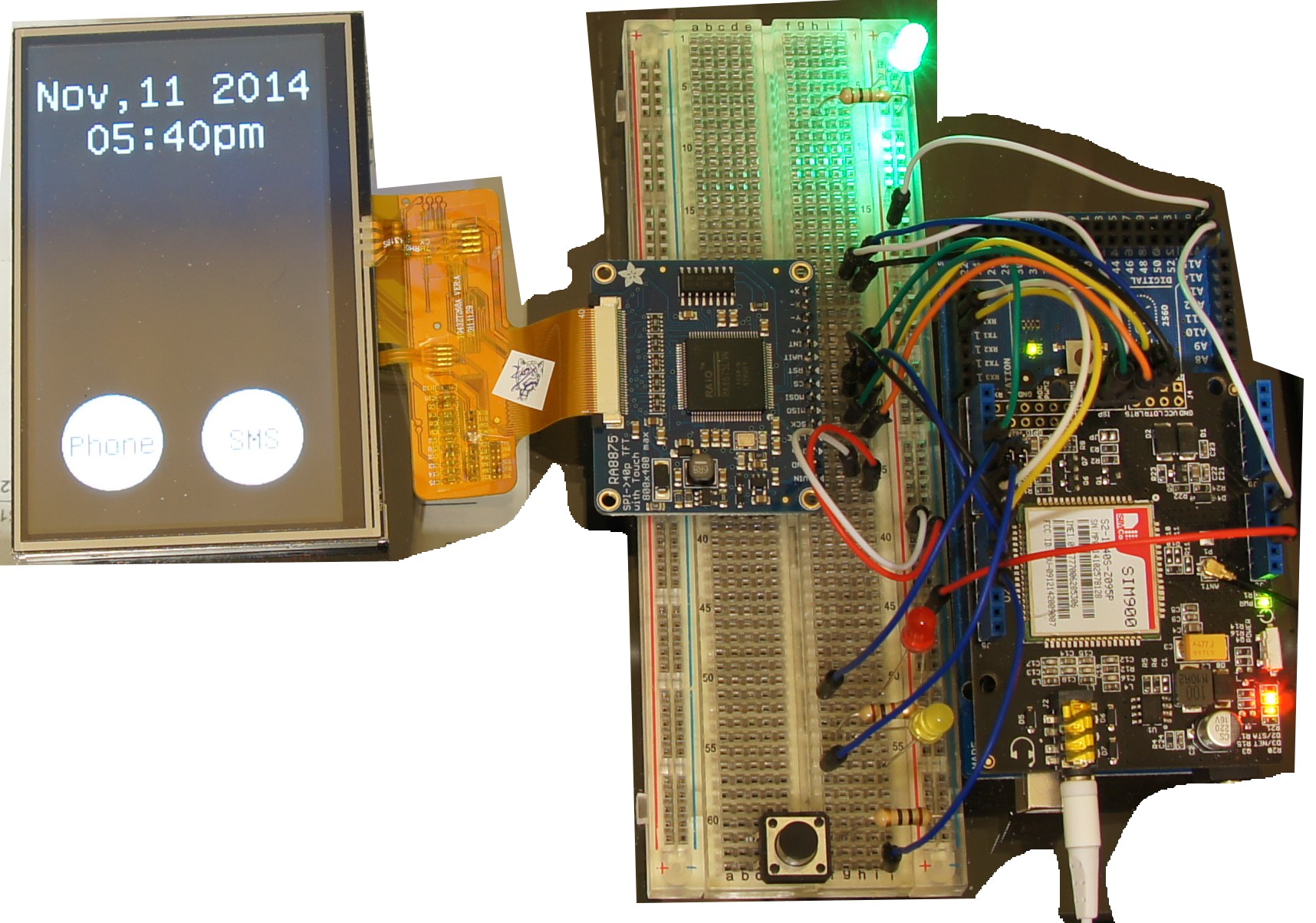
==================================HOME SCREEN==================================
![]()
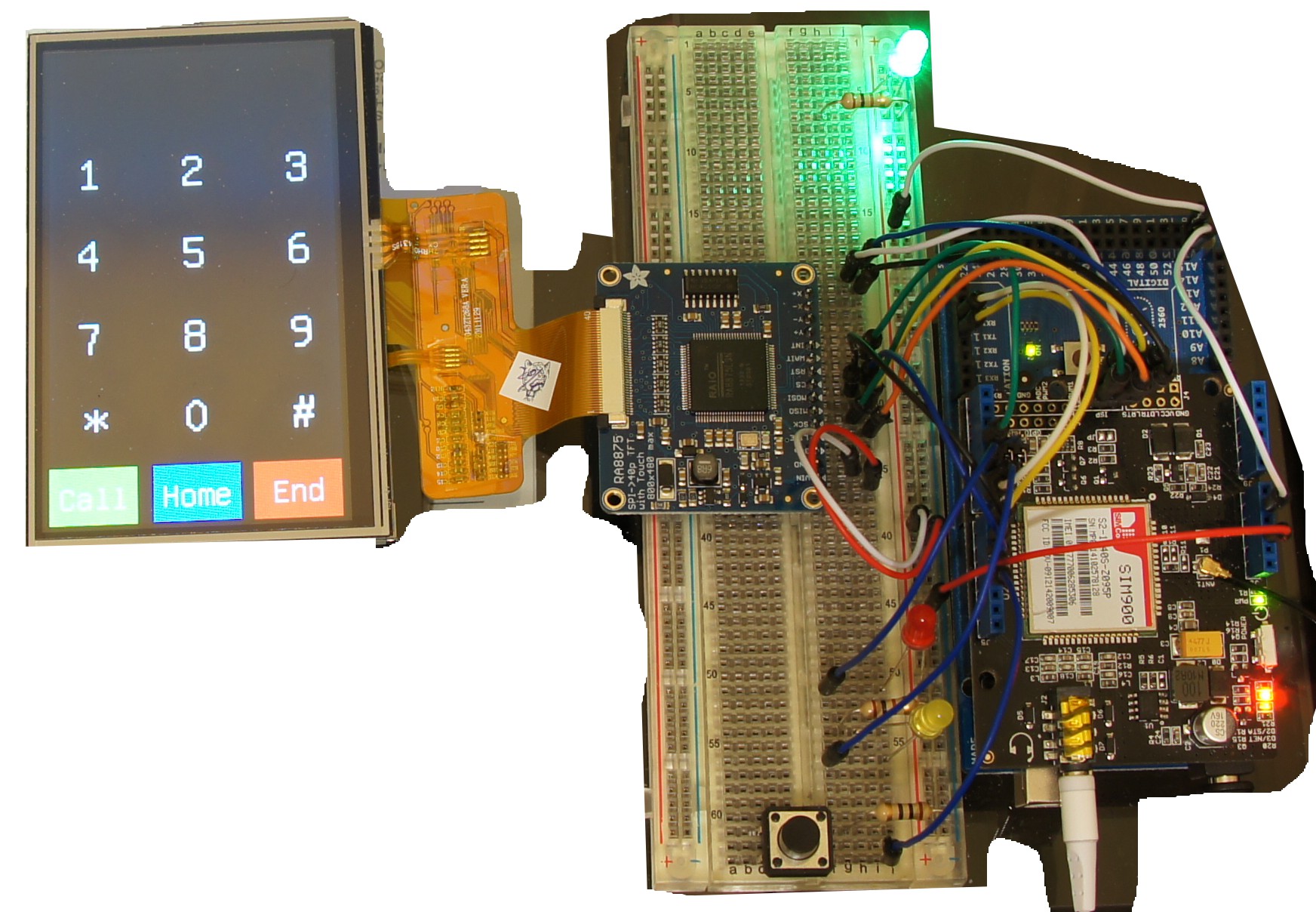
=================================PHONE SCREEN=================================
![]()
==================================SMS SCREEN==================================
![]()
=================================ANSWER SCREEN=================================
![]()
-
Working Phone....somewhat
10/19/2014 at 05:50 • 0 commentsSo I know its been a while but this is a good update. I have completed all the software required to dial out, look at the number dialed, call, answer, receive, clear the screen etc. It tooks a little bit of doing, and a brilliant idea if I might say so, but the way I made the dial part work was to hack the way cpp uses strings. In cpp it uses a character array in order to store the strings, and you can concatenate the string with an additional character. So I started by first declaring bufStr at "ATD" the first part of the AT command required to initiate a call, then for each touch space area I used bufStr += "(number wanted here". Thereby you enter 10 numbers you get something like bufStr = "ATD1234567890" with all the neccessary digits reuired to initiate a phone call, the only last needed characters are, bufStr += ";\r\n", while the carriage return and newline actually took me reading the HEX code coming from the commands sent from the SSCOM32.exe program, and then back tracing them on an ASCII table to the appropriate characters. Then define a new touch area with the character C, and have it send bufStr by serial1.write() to the GPRS shield, only thing is it needs to be in characters, not a defined string. So that too is an easy fix by using the toCharArray function in Arduino, with the resulting command looking like so
bufStr.toCharArray(charBuf, 16);
Serial1.write(charBuf);16 being the 16 bytes of characters needed to transmit. I then need to create a way to to see the numbers dialed in progress. Suffice it to say, this was much harder, and in the end, I used a switch statement with each touch field. I guarantee this isn't the best way, but at this moment, I couldn't find any other way to do it, and I tried a few, but I also guarantee its my inexperience in coding, so please chime in and correct me if you can or want. So an example for the "1" digit it looks like
if (tx > 605 && tx < 675 && ty > 185 && ty < 305) {
delay(50);
bufStr += "1";
place++;
tft.textMode();
tft.textRotate(true);
tft.textColor(RA8875_WHITE, RA8875_BLACK);
tft.textEnlarge(2);
switch (place) {
case 1:
tft.textSetCursor(75, 40);
break;
case 2:
tft.textSetCursor(75, 60);
break;
case 3:
tft.textSetCursor(75, 80);
break;
case 4:
tft.textSetCursor(75, 100);
break;
case 5:
tft.textSetCursor(75, 120);
break;
case 6:
tft.textSetCursor(75, 140);
break;
case 7:
tft.textSetCursor(75, 160);
break;
case 8:
tft.textSetCursor(75, 180);
break;
case 9:
tft.textSetCursor(75, 200);
break;
case 10:
tft.textSetCursor(75, 220);
break;
}
tft.textWrite("1");
delay(50);
}with place declared at the top at 0. In this way each character is written in order, by the number in the array it falls to. Last is to place the call with touch zone "C"
if (tx > 800 && tx < 1024 && ty > 0 && ty < 200) {
delay(50);
if (bufStr.length() == 13) {
bufStr += ";\r\n";
bufStr.toCharArray(charBuf, 16);
Serial1.write(charBuf);
// reset string
bufStr = "ATD";
// clear onscreen display
tft.graphicsMode();
tft.fillRect(75, 40, 75, 200, RA8875_BLACK);
place = 0;
}
delay(50);
}I have it reset the string each time whether C, A, or H was touched, letting H be almost a clear on all accounts. And to clear the text of numbers dialed I just draw right over the top of them. At some point in the future I want to be able to backspace a character, display a call coming in, have dynamic screens, and ultimately have text messaging, as right now all texts have to be answered by my computer. And I haven't really looked further into off storage of texts, but a while back I saw an AT command for offload to storage, so I'll be exploring that further. Anyway good luck and have fun, next post will be all the units in a portable container.
-
Learning, Refining, and Ordering
08/25/2014 at 05:18 • 0 commentsSo today was pretty much a day of reading, experimenting, failure, more reading, experimenting failure, in fact this last statement could be put into a while statement for when c=0, c==20, c++ to say the least. But with each failure I learned something more that I either knew an immediate solution, knew what to look for, or know I don't know how to solve it yet. So the first problem with with the programming port on the Due. The Due wouldn't upload correctly continuously, so my first solution was to reset the com port in windows, in this case I just went through the driver manager and changed the com port to port 5 and noticed you could change the baud rate....hmmm....that might be nice, faster uploading on the Due perhaps, set to 19200. Well the com port change didn't help, so next, google it. I read through some forums where people were saying that R23 is 10k when it should be either shorted or 1k to be safe. So I went hunting through the schematics and diagrams of the Due to find that indeed R23 is in series to the RESET for the Due, with an high ohm internal pull-up resistor 10k in series would significantly drop the voltage not allowing the RESET to go high, but this doesn't apply to me as my Due has the updated board with 1k ohm R23, damn, but there in lies the solution, the RESET probably isn't getting pulled high or perhaps some off pin needed to through into programing, as I do have more boards and chips being supplied by the ever so finite USB port. So I threw on an external power supply at DV 9v 800ma and sure enough that's all it took, programing and uploading fixed.
Next was trying to register touches on the screen, yet for some reason when I did so I couldn't register any touch, well time to dive into the libraries and RA8875 reference. The solution lied in the fact that in order to receive touch input from the registers you need to enable graphics mode with
tft.graphicsMode();
so in the end another simple fix.
Next was to create a layout that allowed me to draw a matrix of x and y values that when touched would output a specific function or character, while doing once, yet allowing it to be repeated, but only repeated after so long. Yeah. That one took a while. First I needed to specifically map out the pixels I wanted to use as input, next I needed to define the matrix per number on the pad as a specific output, but worst was trying to get the de-bouncing gremlin/demon/asshole to stop inputting two characters, this took a while to find a perfect or near perfect solution. In the end the best was to use a timer that I could use an if statement asking if the timer had passed a certain amount of milliseconds then read the value of tx and ty and perform this function,
//variable definition timelast
long timelast = 0;
//the if statement
if (millis() >= (timelast + uint8_t(250)))
which just says if millis() is greater than or equal to the variable timelast plus 250 is satisfied then perform
if (tx > 605 and tx < 675 and ty > 185 and ty < 305)
{
delay(50);
Serial.print("1");
delay(50);which uses a second if statement to ask if a touch has been detected in the matrix defined, delay 50millis print to the console 1 then delay another 50 millis, which then repeat for other numbers like so
if (tx > 108 and tx < 180 and ty > 443 and ty < 577)
{
delay(50);
Serial.print("0");
delay(50);with all the center points and boundaries defined in the note in the sketch, and last the end of the original if statement
timelast = millis();
which just takes the value of millis as of that point and redefines timelast. This solution works pretty well, the input is pretty steady and consistent, while allowing for normal dialing speed, and repeating numbers in the dialing sequence. All the new code and files have been uploaded to use or follow along. My step is to take the input from the number pad, create a value, store the value in a buffer of some kind, then when asked input buffer into an AT command and write to the GPRS shield effectively completing the first call from the phone using nothing but the components.
I'm also looking for a name for the phone, so far I've only come up with Genesis and LibrePhone, let me know what you think or if you have something better. As always happy hacking
-
Number pad and Screen orientation
08/23/2014 at 20:22 • 0 commentsSo today I've been working on the numberpad and screen orientation as before I had to work upside down, and the orientation of the number were flipped left to right and visa versa, so now all thats solved. It was actually a pretty simple fix, if you look at the reference for the RA8875 on page 19 you'll see you can change the vertical and horizontal scan directions by writing to register 0x20 and change the 3rd and 2nd bits, 3rd being horizontal and 2nd being vertical. So by add the code
void Adafruit_RA8875::scanV_flip(boolean V_scan)
{
if (V_scan)
writeReg(0x20, (1 << 2));
else
writeReg(0x20, 0);
}
void Adafruit_RA8875::scanH_flip(boolean H_scan)
{
if (H_scan)
writeReg(0x20, (1 << 3));
else
writeReg(0x20, 0);to the .cpp file or the c++ file, which just says to add the function scanV_flip with boolean input and scanH_flip with boolean function. In each function we write a 1 binary bit to the correct bit in the 0x20 register while leaving it a 0 otherwise or its normal/default. Next we need to add the functions in the header by adding the lines
void scanV_flip(boolean V_scan);
void scanH_flip(boolean H_scan);Now to call it up in the arduino IDE the function
tft.scanV_flip(true);
to flip the vertical scan, and
tft.scanH_flip(true);
to flip the horizontal scan, effectively giving us control over what the display looks like from all orientations and displayed text orientations. I can now see as I hope you see that c++ not only a fun, versatile language to learn but easy too, as I've completed this with no prior knowledge of c++.
All files have been added to the Github repo, with all files released under the same original license in hopes the code will be included in the adafruit libraries from default. Here is what the prototype and display looks like now with the screen reoriented and the number pad drawn. You'll see that in the previous arduino sketch I had the background white and numbers black but I decided to flip them to save on battery consumption in the future.
![]()
As you can see I've changed a few of the wires, the SPI reset and Vcc is held off to the side, while pin 9 and 10 are now reset and CS respectively, this was mainly done because the CS on the SPI or pin 52 didn't seem to be working everytime and sure enough if you look at the pinout for the Due on the repo in references you'll see its not recommended per se. And the RESET is easier to soft reset rather than reset the arduino to reset the screen.
Its my girlfriend's birthday today so I probably won't get any more work done, but I'll be back on tomorrow, enabling the first of the touchscreen and input. Until then happy hacking
-
Prototype under Development
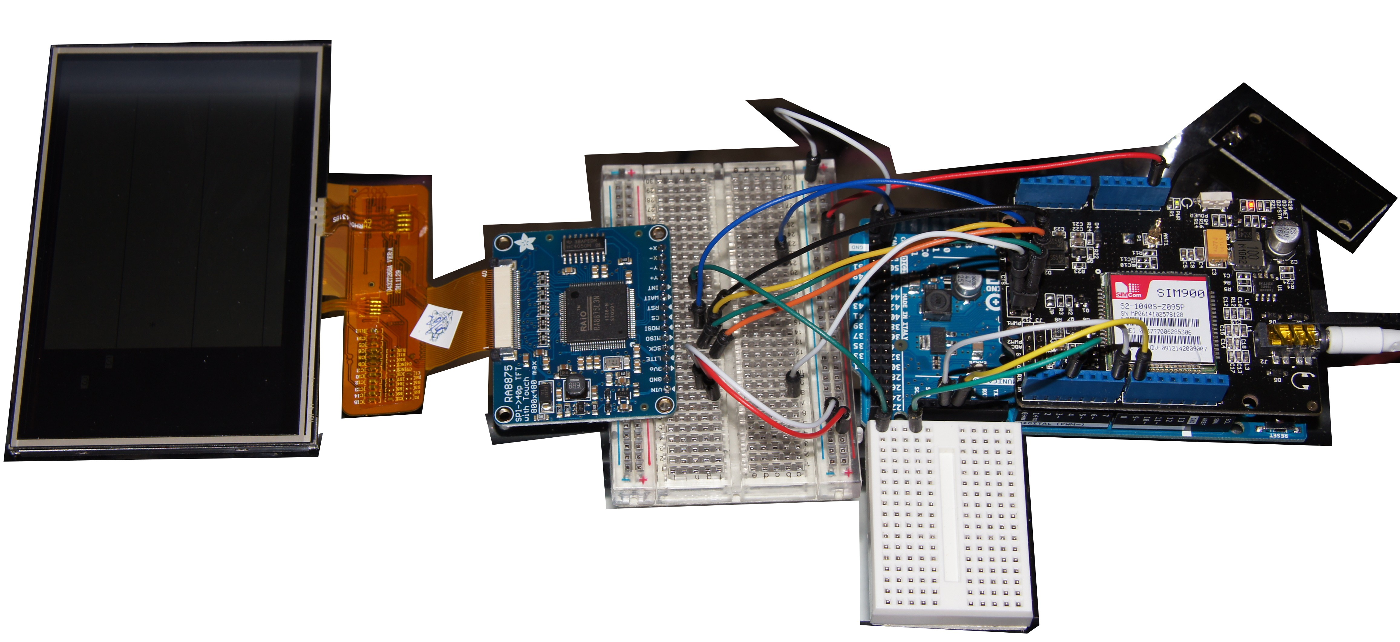
08/20/2014 at 06:24 • 0 commentsSo I had ordered a Due, 4.3" TFT touch screen, and RA8875 driver from adafruit that arrived today 8/19/2014, and quickly got started on the programming and such here is what it looks like so far with the background cut out to make the components easier to see
![]()
I've got the display up and running aside from the GPRS shield that still works but the two are not working together yet. I spent most of the day writing, rewriting and such. I also learned a great deal more c++, and byte registers and such, and improved the library from adafruit to include a rotate text function now defined as textRotate(boolean), cool ay. I'm having a blast with this project as I've never taken any classes nor learned a programming language so I'm teaching myself as I go along. I've created a new prototype project sketch and will include the new libraries and references on the github site. In order to use the Due you'll need arduino-ide-beta which currently is 1.5.7 which i have included the msi in the github as well.
Now for the what I've done and why, first adafruit was kind enough to include libraries to the RA8875 the .cpp(c++) file and the .h(header) file, thank you for that. by examining the header file you can quickly see all the different functions available that is written. The files on the github are the ones I've modified to include the rotate text function, check out the modifications to see how I implemented them. In the datasheet to the RA8875 page 20 you'll it defines that function as Reg(22h) with bit 4 being the flipper, 0 normal 1 for 90 degress rotate. So I read up on c++, examined the other functions in the .cpp file that define the functions, wher I reverse engineered and hacked my way to a boolean function to define the 4th bit, which if I read everything today and understood it, it means in the register 0x22 or 0b0010 0010 we change the 4th bit 0b001[0] 0010 to one, to read 0b001[0] 0010. To accomplish this I wrote
void Adafruit_RA8875::textRotate(boolean on)
{
if (on)
writeReg(0x22, (1 << 4));
else
writeReg(0x22, 0);
}in the .cpp file just below enlarge in the text definitions section. What this means is to first define a function named textRotate, so when we use the arduino IDE we can just say tft.textRotate(some value here);. Then the (boolean on) means the value to input is either true or false, the next bit (tiny joke) is on what happens if we change it. As written the function says if true then write to register 0x22, bit 4 a value of 1, otherwise just write 0 instead, end function. The (1 << 4) means that change the 4th bit to 1, just as we needed as stated in the datasheet to rotate the text. Next we need to include the function in the header file, so under text functions we add the line
void textRotate(boolean on);
and thats it. Now when we are programing inside the IDE we can call the function by textRotate(true); to change the orientation of the text, cool huh?
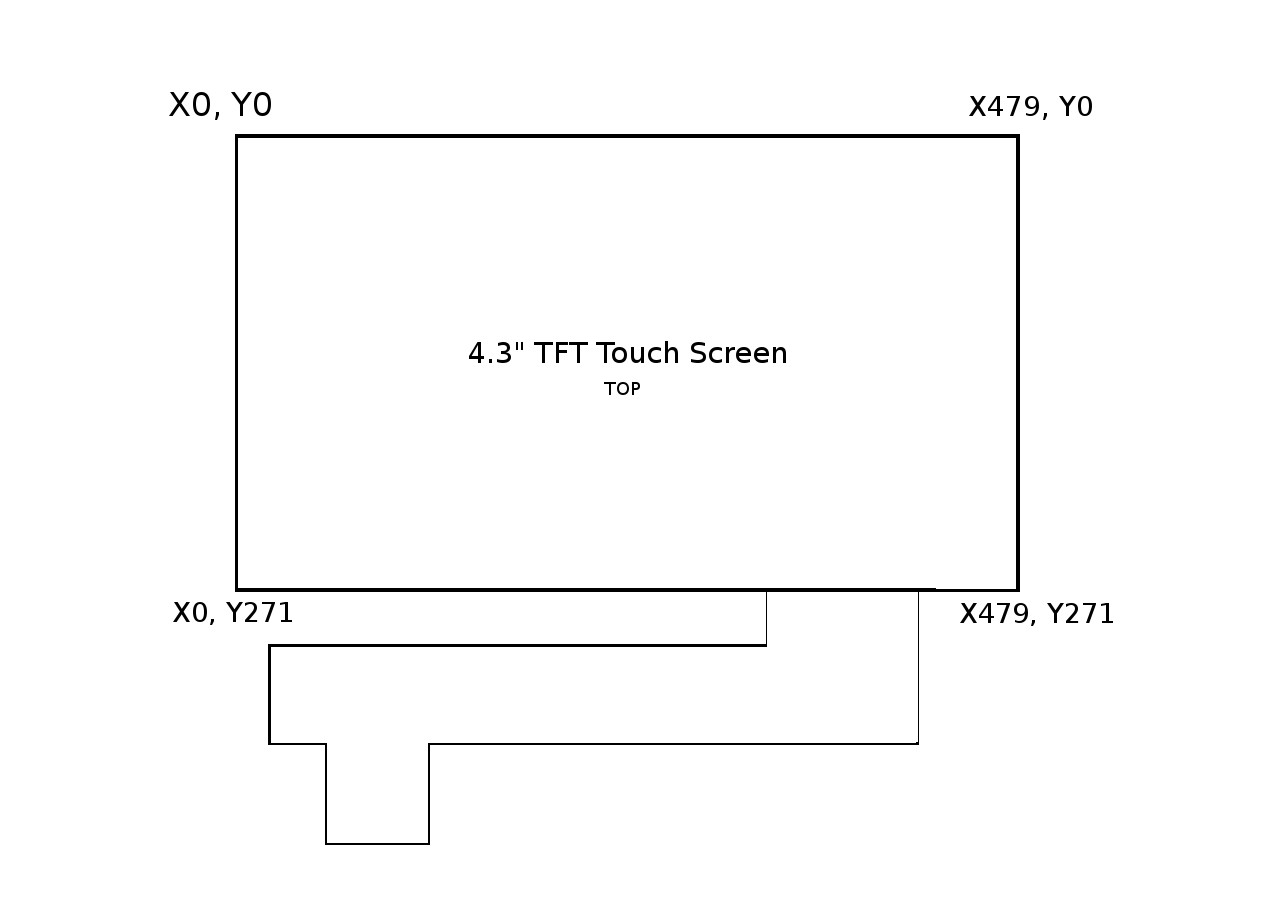
I also experimented with the display to get to know its capabilities and parameters. First thing is the Max values for both x and y are one pixel less the the actual count of the display. With the grid layout as see here
![]()
So lets say you wanted to draw a rectangle for half the screen, write tft.fillRect(0, 0, 240, 271, RA8875_RED), this will fill the screen half way horizontally. The parameters are (X0, Y0, +X, +Y, color) or (X0, Y0, W, H, color), the starting pixel is always top left, and for rectangles you say how much to add in pixels to form next corner, then it fills the enclosed space with the color specified, which the colors defined are found in the header file under // Colors (RGB565), which you can just insert as stated above. To draw lines use the same syntax as above except tft.drawLine(X(start point), Y(start point), X(end point), Y(end point), RA8875_RED);. So if the statement tft.drawLine(0, 0, 479, 271, RA8875_RED); this would draw a red line from the top left to the bottom right. You'll see that in the Prototype sketch there is some experimenting with text and some lines, which will turn into a number pad, that when a touch is registered in that space, that corresponding number will be written to a buffer in line with the corresponding AT command for the desired function, at which time a touch on the screen will initiate the and transfer the buffer and, fingers crossed, will send the command to the GPRS shield and register the correct desire.
-
Beginings of a Pre-Prototype
08/18/2014 at 07:11 • 0 commentsSo I wasn't able to get much work done today, but rest assured I'll be back tomorrow for more updates, and a working pre-prototype portable phone, no bells or whistles, just runs on battery and call, text, and answer all from one simple, portable device.
So far today I've just been learning about the serial for the LCD display, and wiring up the buttons to test, which I plan to implement as an array for the AT commands as a number pad. As you can see below
![]()
I've got the basic setup ready, with my display figured out, my next goal is to implement the commands in a serial form when pushed. I've written a basic sketch I wrote tonight while extremely tired so its probably a little sloppy, and doesn't work, but you'll get the idea of where I'm going with it. The new file named PrototypePhone.ino is up on github, have fun and I'll see you tomorrow.
-
Hardware Serial through and through
08/17/2014 at 03:55 • 0 comments8/16/2014
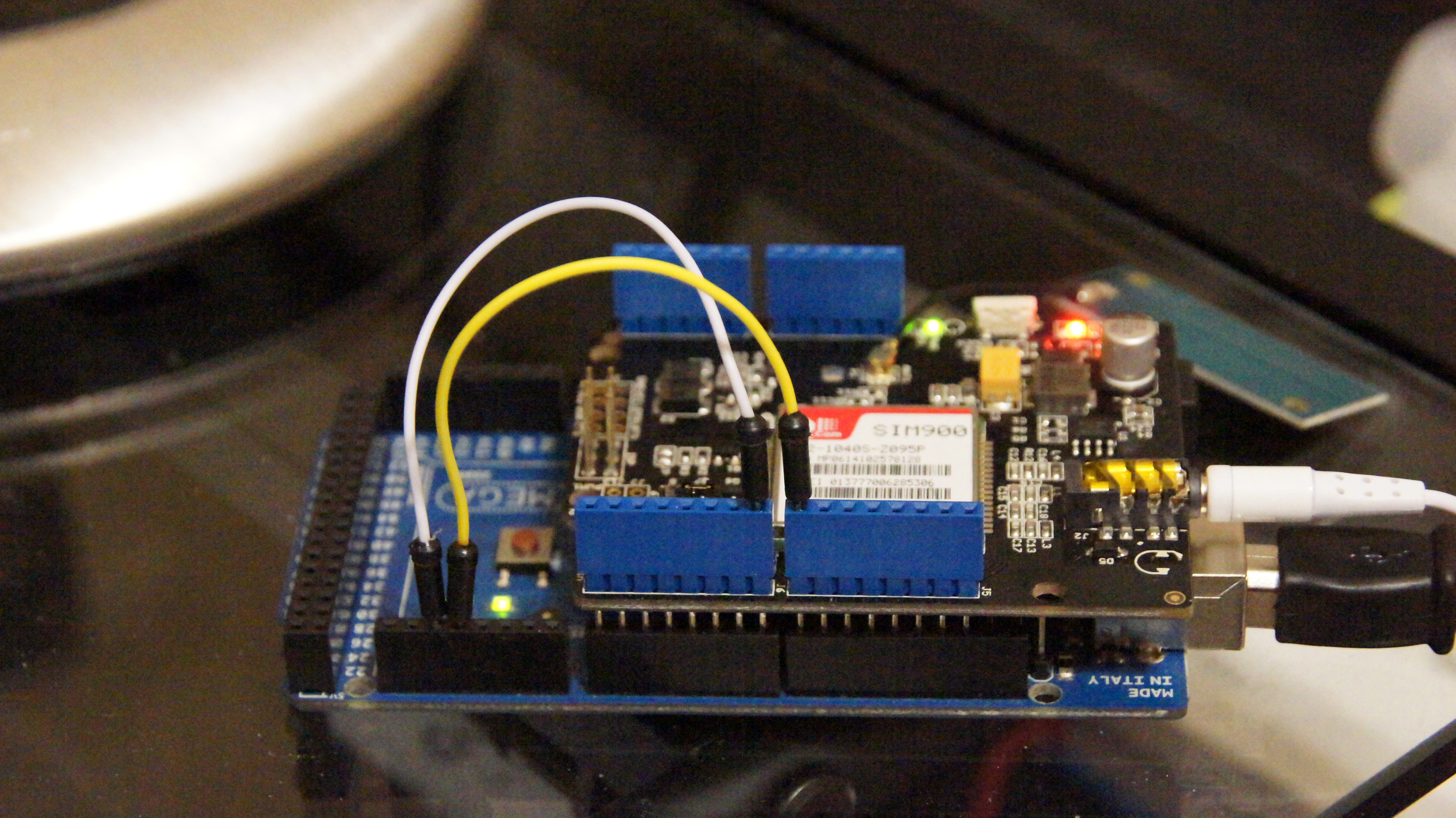
So I did some reading on the Mega and its extra serial ports, and the coding involded ect. and switching the software serial port to hardware is really quite easy. On the mega the extra serial ports are labeled such as Pin19 is RX1 and Pin18 is TX1. So first add the two jumper cables to the new pins like so
![]()
What would be Pin7 needs to connect to Pin19/RX1 and Pin8 connects to Pin18/TX1
To change the software settings lets examine our arduino sketch, even the software changes are easy, I just used find and replace
//Serial Relay - Arduino will patch a
//serial link between the computer and the GPRS Shield
//at 4800 bps 8-N-1
//Computer is connected to Hardware UART
//GPRS Shield is connected to the Software UART
#include <SoftwareSerial.h>
SoftwareSerial GPRS(50, 8); //RX pin, TX pin
unsigned char buffer[64]; // buffer array for data recieve over serial port
int count=0; // counter for buffer array
void setup()
{
GPRS.begin(4800); // the GPRS baud rate
Serial.begin(4800); // the Serial port of Arduino baud rate.
}
void loop()
{
if (GPRS.available()) // if date is comming from softwareserial port ==> data is comming from gprs shield
{
while(GPRS.available()) // reading data into char array
{
buffer[count++]=GPRS.read(); // writing data into array
if(count == 64)break;
}
Serial.write(buffer,count); // if no data transmission ends, write buffer to hardware serial port
clearBufferArray(); // call clearBufferArray function to clear the storaged data from the array
count = 0; // set counter of while loop to zero
}
if (Serial.available()) // if data is available on hardwareserial port ==> data is comming from PC or notebook
GPRS.write(Serial.read()); // write it to the GPRS shield
}
void clearBufferArray() // function to clear buffer array
{
for (int i=0; i<count;i++)
{ buffer[i]=NULL;} // clear all index of array with command NULL
}To setup extra serial ports just change a couple lines of code first we delete the lines
#include <SoftwareSerial.h>
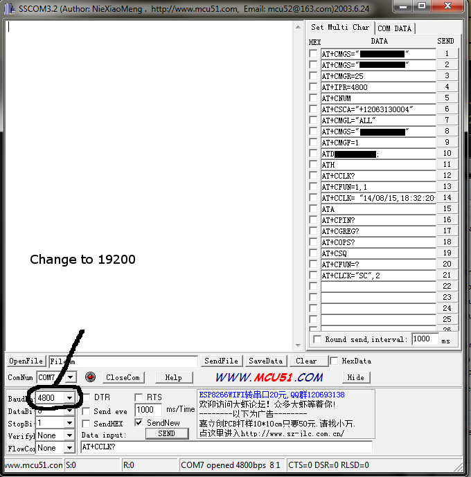
SoftwareSerial GPRS(50, 8); //RX pin, TX pinthen replace the invocation of GPRS with Serial1, simple right? But don't upload the new code yet, first we need to tell the SIM900 module to start talking at the new speed. First open back up the program sscom32e.exe, and send the command
AT+IPR=19200
This will change the baud rate of the SIM900, after which change the baud rate used in the program, then close the port (CloseCom button) or close the program
![]()
Then upload the new sketch, open the sscom program, reopen the port and start sending commands
A new file has been uploaded to the github named GPRS_HardwareSerial_Test.ino with the modifications already made for the hardware serial, and the previous GPRS_Test.ino file has been named GPRS_SoftwareSerial_Test.ino
For more information on the Mega and the extra serial ports and how to use them refer to here.
Open Source Cell Phone
A completely open hardware and open source software cell phone