-
Build log - take 2
05/23/2017 at 20:29 • 0 commentsBuild pictures
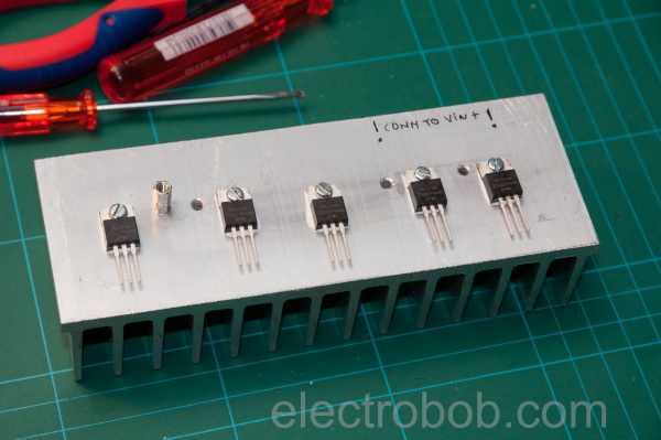
Transistors tanning. Notice how this heatsink has been through a lot…lots of holes.
First tests, including cooling:
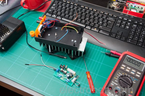
Preparing to put things together:
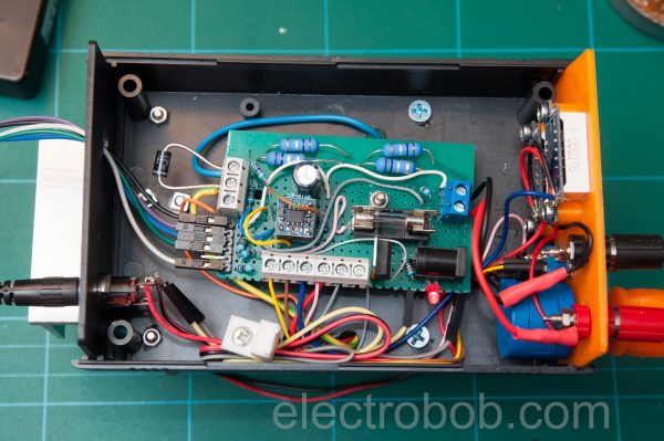
First test. The front panel is 3D printed. Also the knob, I did not have one for perfectly cylindrical shaft multi-turn potentiometer.
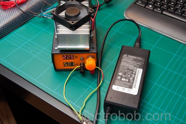
Testing the power brick guilty of burning the previous transistors. After a long time, the heatsink reached about 45°C in the middle at the well cooled area and 53°C at the edge fins where there is not much air flow.
And finally testing the speed using a 7805 regulator and short output wires using a 10kHz, 1A load. The rise and fall time are about 2.1µs.
-
Take 2
05/23/2017 at 20:28 • 0 commentsThere are some improvements, so let’s go through the schematic first. The way it works is simple: U1A will drive Q1 such that the voltage across R6 is equal to the reference at it’s positive input. This in effect creates a constant current being drawn from the test power supply.
In “external mode” the constant current load is controlled and read out by the Analog Discovery. Since the control signal can be up to 5V, with R5 being 0.1Ω, I have divided it 10 times using R2-R3, to limit the max current to 5A. In “internal mode” there is a fixed reference generated using RV1 and a 5V regulator, which makes the supply draw a constant, adjustable current.
For a nicer look, I added 2 meters, they are your typical 3 wire voltmeters, but make sure you get the nicer ones which auto-scale and use all 3 digits for precision under 10V which are also hackable. The current meter needs a 10X amplifier first, since we are reading current on a 0.1Ω resistor.
Finally, let’s look at the extra safety features: first, I am now using 5 transistors instead of 3, of similar type. I have added a rather large, 0.5Ω balancing resistor in each source, made by 2 1Ω/0.6W resistors in parallel (remember, built out of what I had in my component drawers). And second, a Zenner diode between the source and drain. This will serve 3 purposes: if the load is applied with reverse polarity, the fuse will blow and it will also protect the transistors from high peaks when a load is disconnected. Third, if more than 36V is applied, it will blow the fuse. The nice thing about using a Zenner like this: if a high enough current is passed through, it will melt and become permanently a short: it forms an anti fuse.
Oh, and did I mention I want it to be fast? Well, that is why I used a TL3472 (besides that I had one): it has a rather high slew rate and a high output current capability.
-
Take 1
05/23/2017 at 20:27 • 0 commentsThe simplest of design, one OP-AMP driving 3 MOSFETs. All fine until I made a mistake: with the signal generator connected and turned ON, i connected a 24V 5A supply that was already on, while the signal generator was providing a square wave for 5A current. This caused one of the MOSFETs to blow up (shorting) due to an avalanche event. Finally the power supply went into hiccup mode.
Have you ever seen a fuse pulsating? With the output of the supply shorted and the fuse quite at the limit of the current, it is almost melting each time the power supply tries to restart
-
Testing the Peaktech 6225A
05/23/2017 at 20:14 • 0 commentsUpdate: Check the PSU Burner being tested with a real power supply in my PeakTeck 6225A review.
PSU Burner
What does one do when designing a power supply? Well, build a power supply tester, of course.
 electrobob


