Jarrod
-
Hardware and basic SW release
12/03/2015 at 07:04 • 2 commentsIt's been a long time between posts, I've just moved to the USA, started a new job. But I have been able to start working on this motor control again. Purchased some new batteries (8x 15Ah LiFePo headway cells with a BMS!!) and am starting to work through getting my bike up and running.
If anyone has been following and wants to try building a motor control, now might be the time to take the dive because...
I'm releasing hardware V5.0 incorporating:
- A (working + tested) over current protection implemented in hardware.
- All logic on the power board now uses the same 3.3V rail, simplifying the power supplies.
- 5V buck exclusively for phone charging and other external circuitry.
- Capability to mount a daughter board directly to the power module for bluetooth support etc.All in all, while I'm yet to drive serious power through it, I feel this hardware is quite stable.
Files created in Altium Designer btw. I'm looking into converting it over to CircuitMaker.
And I'm also releasing some software to make it run. it's still pretty fundamental, I've zipped up a cut down version of Motorware 12 (which is a few versions behind the current 15, but I haven't had time to update my code base, I've modified a bunch of files to get my hardware and the serial port working) So all that's required to compile, debug and run is TI's IDE, Code Composer Studio (I'm running V6, the latest). Create a new workspace and import the projects from "solutions\instaspin_foc\boards\boostxldrv8301_revB\f28x\f2802xF\projects\ccs5"
The software I'm running on my bike is a modified "lab 5a" It drives the motor with constant current based on throttle position, regenerative braking is supported via a second potentiometer. Some basic runtime data is periodically transmitted over 9800baud serial.
Lab 2b is also included for measuring motor parameters, after the software has finished analysing the motor, lab2b has a constant speed mode for testing the motor control and measured parameters, which should then be copied into a new motor profile in 'user.h' before using lab 5.
See TI's instaspin website for the lab user guide which contains all the info you will need to get started.
And please post any comments. Files are in dropbox links on the left.
-
On The Road, 3D Printing and Inflated LiPos
03/14/2015 at 01:36 • 4 commentsIt's been a while since the last update, and much has happened. Good and bad.
To summarize the good, the motor control works well. There are still a couple of known bugs but on the bike test platform it's proven to be quite reliable, I was riding it to work for a few weeks, and did a couple of 50KM to test extended range with pedal power. In total it's probably done about 400KM. Average range with minimal pedaling is 20+KM riding with my undersized 5AH 12-cell pack.
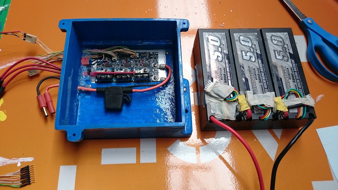
Most of these k's were with the use of electrical tape for battery and wiring containment, and the whole assembly was far from waterproof so some 3d printing was definitely in order. The goal was to create a self contained power box including batteries and electronics with cables exiting for the motor and throttle/brake/head unit. The battery wires and connector loop outside the box for charging.
![]()
I made use of the enable line on the 10V SMPS to completely disable the system using a toggle switch, this means the connection to the battery doesn't really need to be removed as the circuit only draws a couple of mA in its disabled state.
The whole assembly mounts beside the motor on the same aluminium plate... which for some reason I didn't photograph :(
Then came a few dumb fails. First I shorted the 10V line to 3V3 when doing some testing. This killed the uC and logic gates. in hindsight it also seemed to damage the opamps, but not so much that I noticed at the time. So with the uC and gates replaced I took it for the first ride in new enclosure. It was a long ride as I was meeting friends for some mini golf (probably not the best way to test out new hardware configurations.) On my way I was noticing strange behavior above 1/4 throttle, the control scheme would become unstable and at a slightly higher throttle, the OC circuits would kill operation. That would be the zombie opamps. but it ran, and it made it to mini golf, kinda..
On to the next fail, it was a 40KM ride and the battery undervoltage protection involves my looking at the LCD display on the head unit and backing off on the throttle when it gets close to 36V. Lithium has a very sharp voltage/charge curve as it gets close to full discharge so I was happily riding along with reasonable voltage, look at the display a few minutes later and saw I was at ~30V. AHH lithiums don't like this one bit. This was particularly annoying because of how easy it would have been to prevent. Seriously, a line of code in the motor control software! But up til now I had basically ignored battery management.
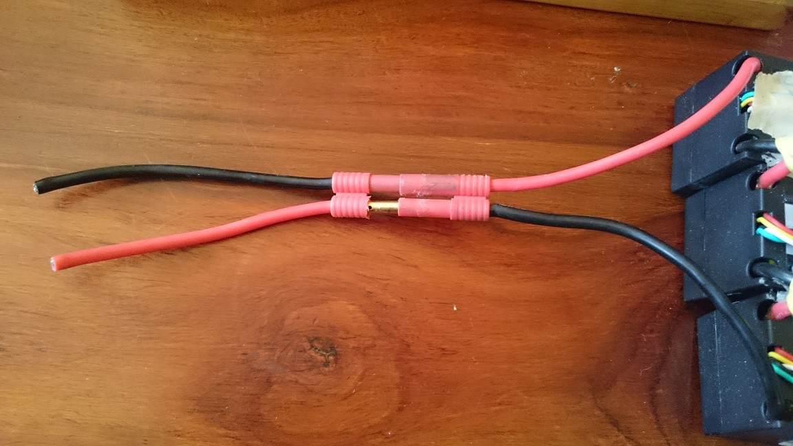
And one more fail just to round things up and go out with a bang. Since the battery connector was glued into the printed enclosure, my hacked laptop charger which I use for charging the cells (constant current, constant voltage booster takes 19V from the laptop brick to 50.4V) I could no longer use the crocodile clips for battery connection (which lets face it, was never a great idea anyway) so I brought a 4mm banana connector with wires to which I clipped the charger. Of course I forgot that the connector would be reverse polarity:
![]()
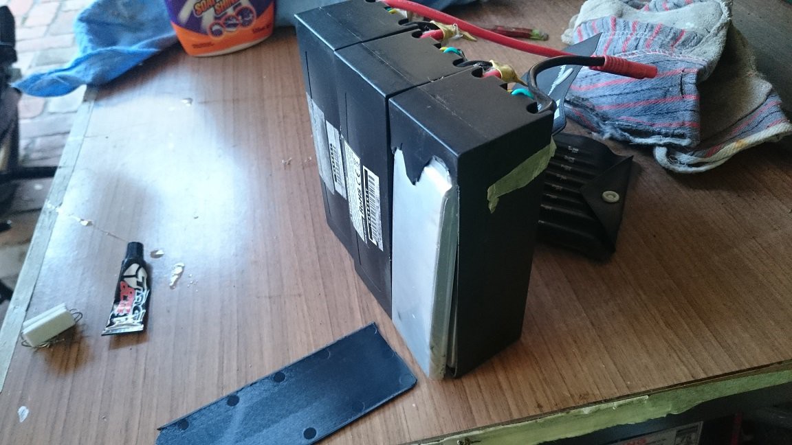
I proceeded to connect negative to black, positive to red and connected the connectors. This lead to a significant arc (100V between the battery and charger, with 2A from the charger and a metric shit-tonne of current from the battery) which welded the connector and finished off the batteries. 1 week later:
All cells are inflated, the hard-case on that one couldn't take the pressure.![]()
I think I have learned my lesson. the next battery pack will have a few improvements:
1) Undervoltage protection either by software on the motor control or with dedicated circuitry and an in-line switching device to disconnect the battery completely to prevent damage.
2) A dedicated charging connector and mating connector on the AC charger
3) Cell balancing to greatly extend battery lifetime over multiple charge-discharge cycles
4) More capacity so I don't have to run the cells to such a low state of charge for any reasonable bike ride length.
And I'll finish this post with some updates on the near future of this project. We want to move away from the modular design and go for a more integrated solution. Ie, have the android communication hardware built into the motor control PCB. This will likely involve a bluetooth module and USB host IC to provide some phone connectivity options. Any expansion can still be done by hooking up a secondary uC to the serial port. A uC for android coms may exist on board, we are still looking in to the feasibility of doing everything in the motor control uC.
Mechanically the bike used for testing will change significantly. I'm thinking of going towards hub motors just for practicality. They tend to be more reliable, quiet and less obvious. plus are already designed and tested for high power ebikes. So the motor control will have it's own printed enclosure. batteries will live on a panier rack. the battery management will be on it's own PCB(s?) and live with the batteries.
-
Dynamic load test
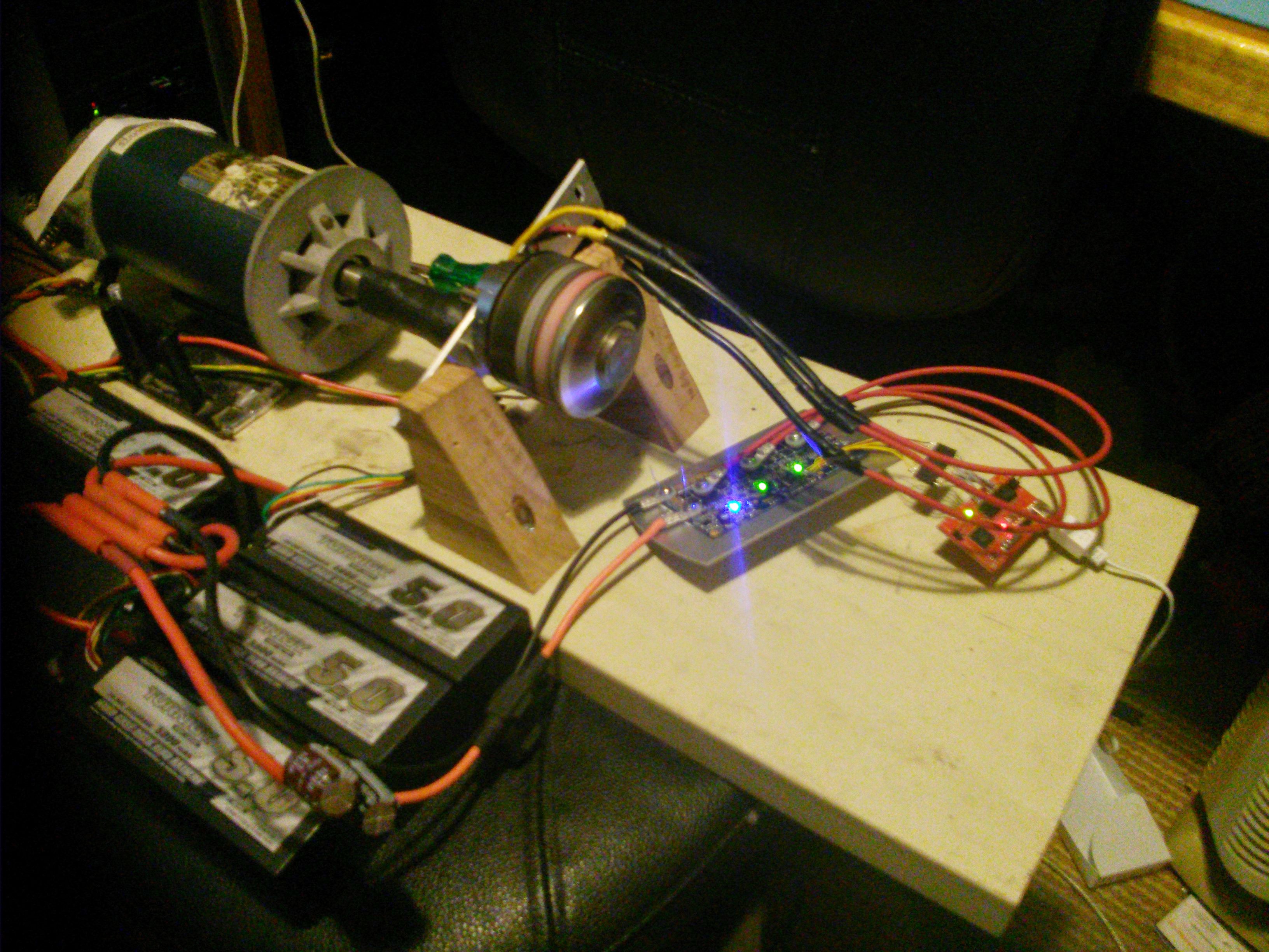
10/22/2014 at 22:02 • 1 commentThe fun stuff begins, motor is spinning but to make software changes we need a bench test setup, this will make it easier to profile the controller and add/verify new features. As opposed to duct-taping multimeters all over a pushbike!
To actually provide a load for the motor on the bench, it is directly coupled to a DC treadmill motor, 180V 6.5A 1HP rated. This acts in reverse as a generator. An electronic load for this generator is required for its use as a variable mechanical load. I figured constant current loading would make it easy to ramp up the mechanical load (since torque is proportional to motor/generator current) but after playing around I think constant power might be more useful, I might use a microcontroller to simply vary the load current depending on generator voltage, or even use the encoder on the generator to implement some sort of torque/speed curve.
The electronic load is simply a MOSFET operating in it's linear region. It's cooled by a PC heatsink. An opamp drives the gate, it compares the voltage across a current shunt and a reference voltage to control the current. I'm using a potentiometer to set the reference voltage but it could just as easily be a microcontroller.
Anyway, video below shows the constant current load getting destroyed by the sheer power of Everywhere Electric ;-) More load FET's needed, as it fails short circuit at around 500W which is actually a very good test, hitting a large load under throttle is what blew up the last revision. This one survived with grace.
Note to self: set up an LCD to show motor controller statistics in real time.
-
Flashing lights and spinning things
10/19/2014 at 12:46 • 0 commentsAt first when I hooked up JTAG things were not looking great, I was getting strange debug errors, so I tried debugging an instaspin enabled launchpad, which worked perfectly and realised I'd forgot to order the "F" piccolo part, ie I'd gotten the piccolo without instaspin built into ROM. The launchpad was sacrificed and the gods were pleased.
So I started off running lab 2b from the motorware lab project set, this lab is intended to run the FOC from flash and do the motor ID process before running the motor with a PID speed control loop. The motor ID process is crucial, it does a DCR measurement on the motor, then spins it up open loop and modulates the stator current to do inductance and flux rating measurements, these parameters are required for the flux estimator to work correctly. On the old V2 hardware I could never get it to complete the ID process without the rotor stopping mid measurement, or doing other unusual shuddering etc, this was a good indication that the controller was getting noisy current and voltage signals which I now believe to be crosstalk between the two (due to ground loops.)
This time the controller ID's and runs the motor up to full speed (4KRPM@48V) very smoothly, startup and low speed operation is perfect. Very promising result for the new board layout.
![]()
-
Power Module Assembly
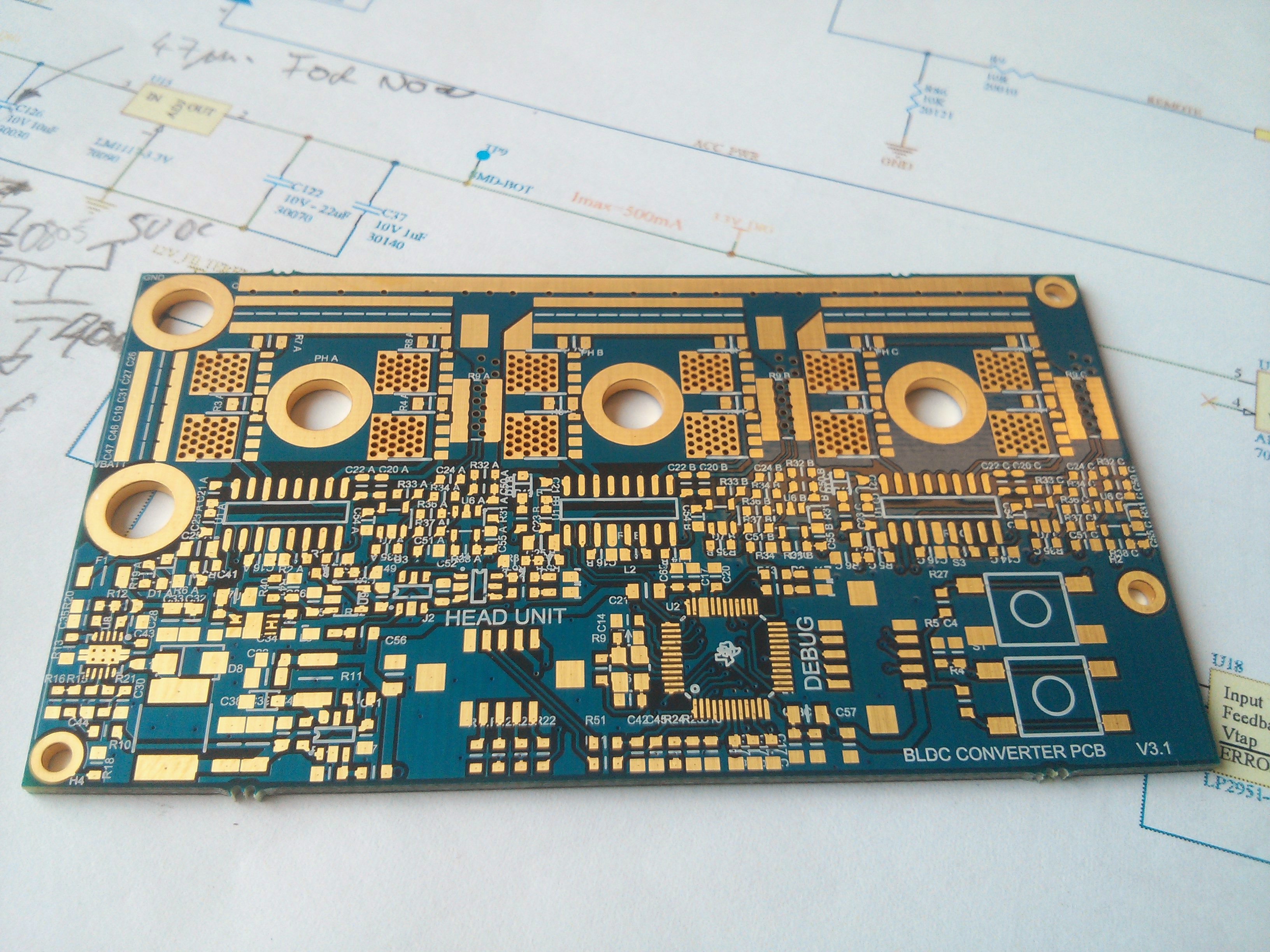
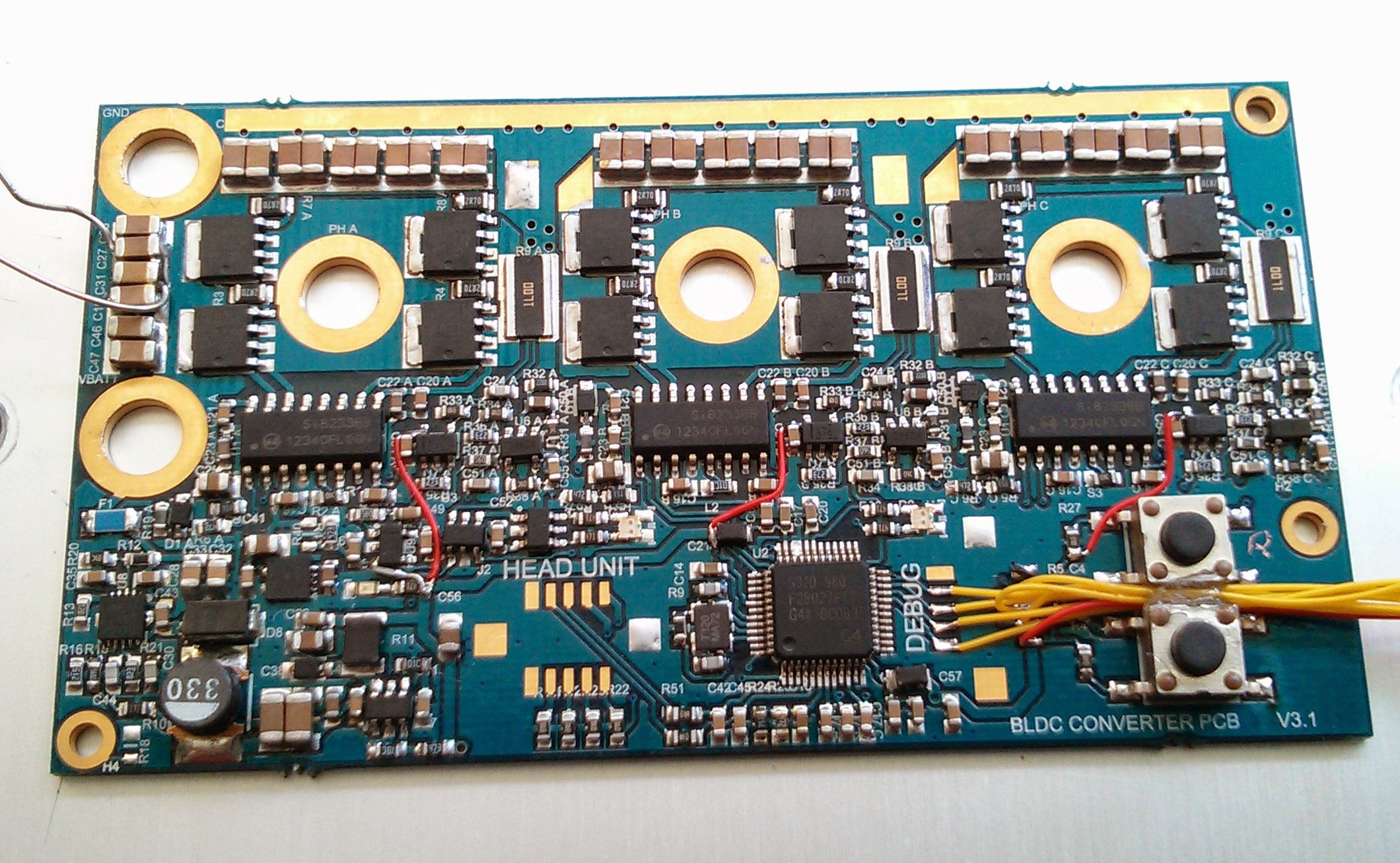
10/16/2014 at 12:21 • 0 commentsPCB's arrived, looks nice in gold :D
Turns out it's slightly smaller than a business card!
![]()
OK I messed up a few designators, was a bit of a rush to get it in the prototype panel at work (it always is)
I figured I'd take this chance to show how I've learned to bring up a circuit. first thing is always the power supplies, nothing will work without them afterall..
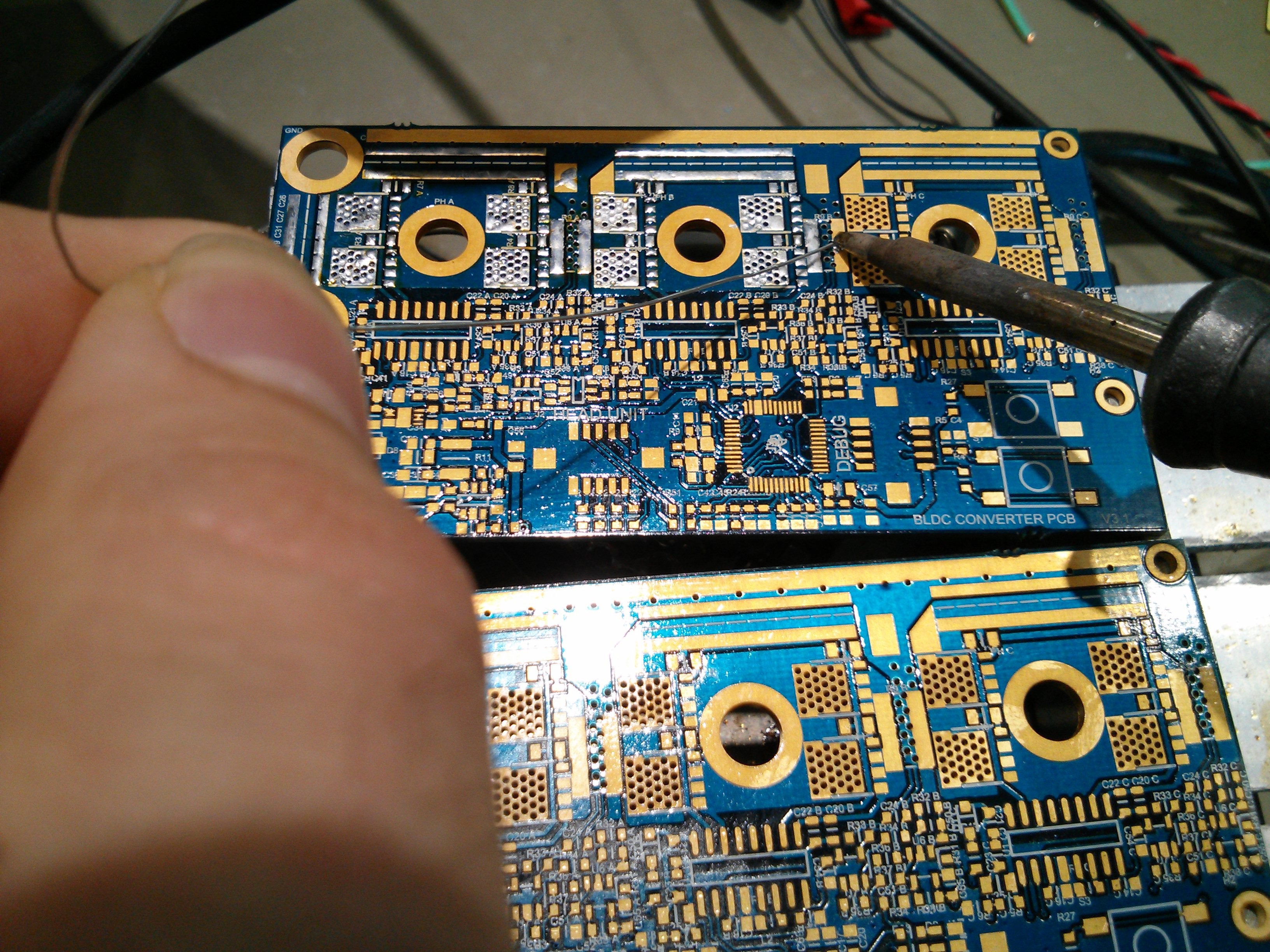
My preferred way of assembling prototypes like this is to coat the board with rosin flux and proceed to add solder to all pads
![]()
Once the pads are coated with sufficient solder, additional flux is used and a hot air soldering gun melts the solder while you place the part with tweezers, usually the amount of solder that is stuck to the pads is enough to attach the parts, if not I'll just go over them with a fine tip iron and additional solder.
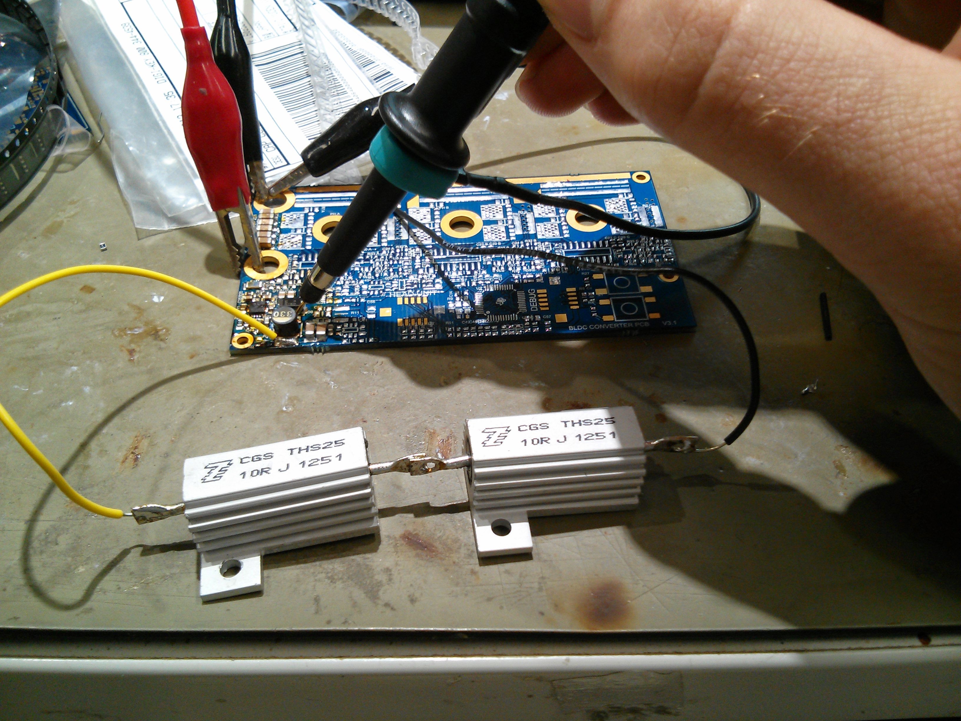
So I started by populating the 10V SMPS as the other rails are powered by this, it's also a circuit that's new to me. I took values from the example circuit in the chip's datasheet and tweaked for my desired voltage. amazingly it pretty much worked first try, always nice!
I approximated the sort of load this psu might see would be <5W, or 10W when charging a phone, so 20ohm and 10ohm loads were used for testing.
![]()
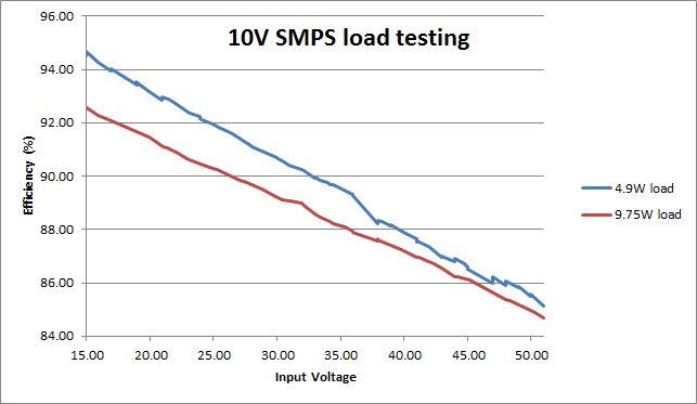
I used the power analyser at my work to check efficiency over input voltage range.
![]()
This shows that the power supply is easily capable of powering the head unit and charging a phone, efficiency does not drop as much as I had feared at full voltage. the thermal vias do their job of sucking heat away as the chip barely gets warm running at 10W. this is delivering 1A, they have rated it for 1.5A output current, at some stage I'll have to go through the maths to check if this configuration will survive that amount, until then I feel safe running it at 2/3rd current.
Next I populated the 3.3V smps for the microcontroller, this was a proven circuit and was no trouble, then the 5V linear reg and the opamp bias rail, U9. Here I realised a mistake, I really should be running all the opamps (which are used to amplify the current sense resistor voltage) at the same rail as my microcontroller, as higher than rail voltages could destroy the chip. First wire mods! yay.. I cut the VCC tracks to the opamp on each phase sense and ran some wire wrap wire to the nearest 3.3v point.
A few hours of placing parts and voila!
![]()
My makeshift jtag connector on the right, I forgot to order the neat little Hirose connecors I had intended to use.
Next I'll see if it will take a program.
-
V3 Hardware Design
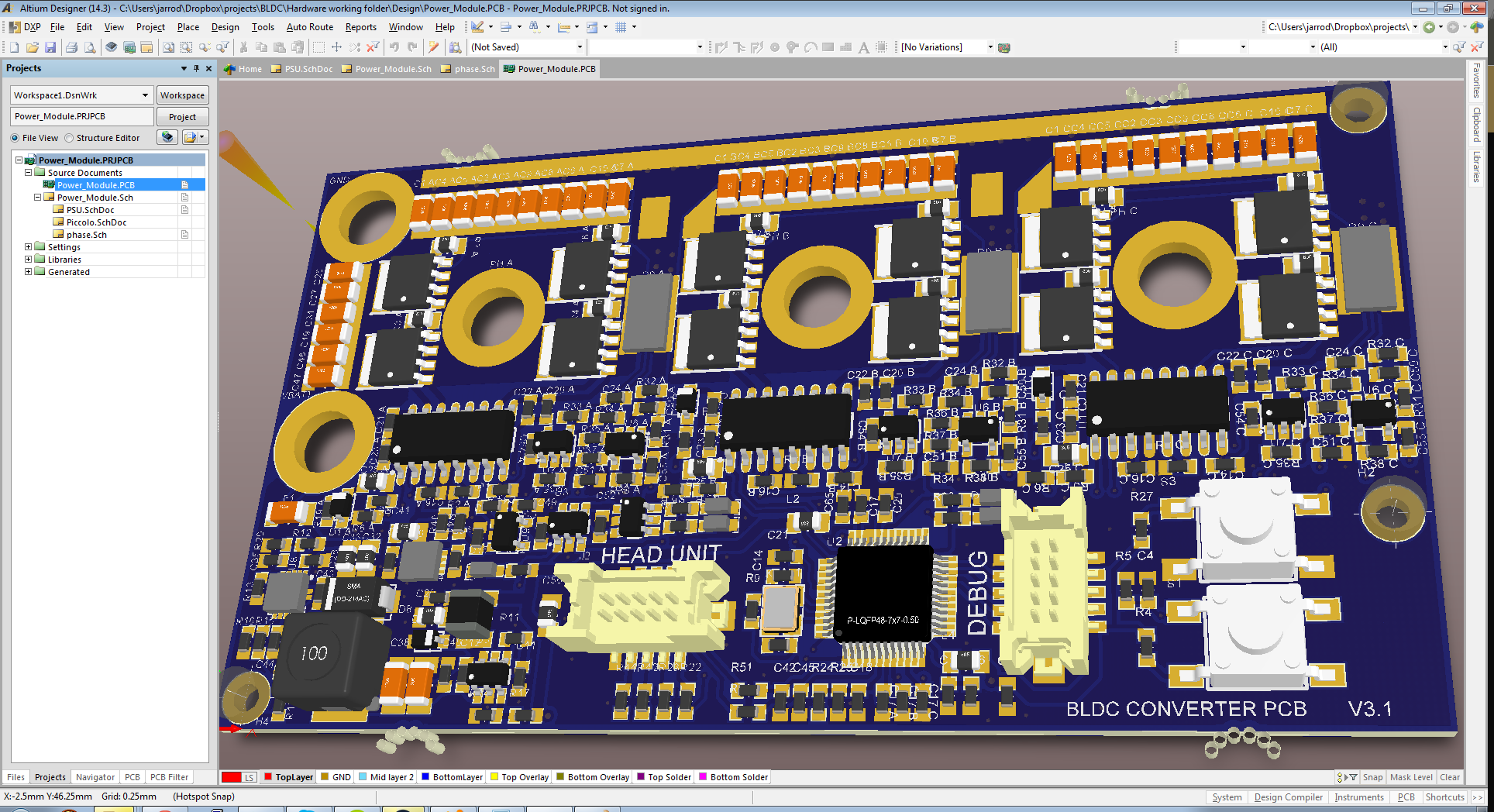
10/11/2014 at 02:33 • 0 commentsIt's been some time since the last update for EverywhereElectric, but we have been working on it! After many hours pushing pixels in Altium, V3 of the PCB is ready!
![]()
I got bored one night and downloaded 3d files for all the components, it is actually very useful for things like connectors and odd components as you can verify footprints and clearance for component placement. And it looks freakin' awesome!
PDF schematic: https://www.dropbox.com/s/0rzs2lx15ip5onw/BLDC%20Schematic.PDF?dl=0
I've done a lot of work around the power supplies, as that was a big issue in the last revision which had startup and minimum load issues, also the 3.3v linear reg for the Piccolo chip would get uncomfortably hot regulating off the 10V rail. the new solution is to buck the battery voltage down to 10V for V_DRV, then run a 5V linear reg and 3.3V smps.
V_DRV (10V) needs to run the gate drives and all other power supplies including the head unit (I figure it's better to have just one rather expensive 60V buck in the system) so I chose a beefy 1.5A 60V buck from TI, the TPS54160. this should have enough grunt to run the phone charging circuit too. or if we decide to have a 60V reg in the head unit then a 0.5A version of this part is available. I'm running it at 850KHz to keep magnetics small.
The 5V line is just running opamps and the logic line in the gate drive chips, a 100mA LDO is used for this.
The 3.3V line needs a bit of current, it drives the piccolo uC which can draw 120mA, a switchmode is used to reduce power loss. I chose a little SOT26 buck from Alpha&Omega, AOZ1282 which I've used in other projects, very easy chip to use, fixed 450KHz makes magnetics tiny, it's good to 1.2A and 35V input.
I updated the connectors to SMD 1.25mm pitch Hirose parts, one for JTAG, one for the head unit/throttle/brake. they are locking (important on a bike!) and the female connector crimps on to stranded 26-32AWG wire. in the last revision we used 0.1" headers, but because they were surface mount (so the pcb can be heatsunk directly to a metal plate) they used a lot of space.
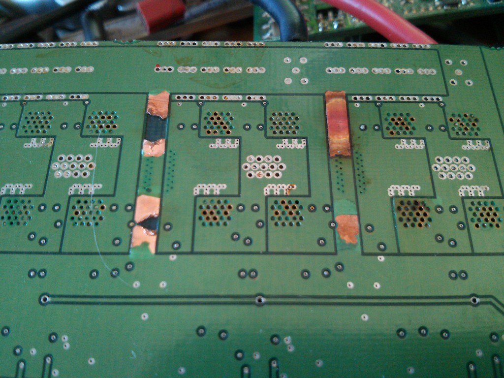
There were some pretty fundamental issues in the last rev which could have caused blowups, the first was a layout issue. as becomes apparent when looking at this catastrophic failure.
![]()
look at all those untented vias! Oh and the fused tracks too ;) The amount of current required to fuse those tracks only occurs if shoothrough of the FET's occurs, but it shows pretty clearly that significant current flows through those tracks running between the low-side shunt resistors and ground, which is also the ground reference for the current feedback opamp, so it would have had this extra V=IR voltage across it, who knows how that would mess with the field estimator algorithm.
To solve this potential issue, I've beefed up the ground return paths on multiple layers and used a star-ground configuration to separate the power and logic sides of the circuit and remove any strange voltage gradients across the ground plane.
Second issue was the over current protection, it worked via multiple comparators which pull the gate drive disable pin low when the current through any half-bridge exceeded the set limit. the problem is that it would re-enable the drive as soon as the current fell. so this would have caused oscillation and each time it all goes overcurrent, the fets become undriven and potentially have diode conduction occurring, reverse recovery time could have caused some amount of shoothrough and shoothrough causes FET's to fuse short, and the image above to happen.
So we want to avoid uncontrolled disabling of the gate drive. I've implemented a bit of logic, first a comparator on each current sense line which detects overcurrent conditions, all these overcurrent signals are OR'd and drive the clock of a D-type flip-flop which disables the gate drive and pulls a pin on the uC low. once the uC sees an overcurrent condition has occurred, it can prepare for it and reset the gate drives by pulsing the reset line on the flip-flop.
A prototype PCB is on it's way now, next post should be assembly and testing!
-
It spins
08/21/2014 at 06:25 • 0 commentsIn case you were wondering - The design shown in our video does actually work. We didn't have it running in the entry video because it failed a few weeks back under a load test where we didn't manage to capture any useful diagnostic signals, we think it's to do with track layout so that's why the dropbox repository contains a completely ripped up PCB file. Here is a video from a few months back.
THIS IS NOT OUR ENTRY VIDEO.
-
Developing the Power module (Part 2)
08/21/2014 at 06:16 • 0 commentsIn the last log we showed how the physical inverter design came about, lets look at the motor control signals are generated.
We keep going on about sinusoidal control. Here is why.
Brushless DC (BLDC) motors are called so because they followed on historically from brushed DC motors, they are in fact a type of AC synchronous motor and are electrically similar. AC motors usually have 3-windings, driven by 3 sinusoids, each 120 degrees out of phase with the next. this generates a rotating magnetic flux in the motor to which the magnets synchronize, resulting in rotation.
Most small brushless motor controllers approximate these sinusoids with a much easier to generate 6-step trapazoid. They can get away with it because BLDC motors are constructed in a slightly different way to your normal AC machine. A lot of literature states that BLDC motors are inherently trapazoidal, and should be driven in such a way. this is only partially true, BLDC motors are constructed using concentrated windings, meaning each winding is confined to it's own stator tooth, AC machines on the other hand have their windings distributed over many teeth, this effectively averages out mechanical cogging effects in the motor and leads to a less distorted sinusoidal EMF profile but it also requires longer lengths of wire and results in heavier motors.
BLDC motors with concentrated windings still produce good approximations of sinusoidal EMF when rotated (hook one up to an oscilloscope and see for yourself)
To make a motor spin you essentially have to produce a voltage that overcomes and advances the phase of any EMF the motor is producing resulting from rotation, therefore you want to match the voltage to the emf profile of the motor. Feeding a trapazoid into a BLDC motor results in wasted current, rough rotation and noise (cogging).
It’s similar to using stepper motors with full-step drivers vs microstepping drivers (which are actually sinusoidal drives)
So by driving our motor with sinusoidal waveforms we can increase efficiency and reduce torque ripple. The cost of doing so is extra computing power and requiring a voltage and current sensor on each phase.
This brings us to the selection of control silicon.
After a few iterations of design, at first using an arduino (only trapazoidal control was attempted), then a fairchild chip, finally a low-power DSP microcontroller - the Piccolo F28027F - from TI is in the current design. Why? Well TI have put a lot of work into making a hugely flexible sinusoidal field-oriented control (FOC) system which is capable of identifying a huge range of motors on the fly and driving them flawlessly, it can meet all of our requirements when paired with custom designed power electronics. TI call their solution InstaSpin-FOC. FOC is a very difficult scheme to implement so by using TI's chip and the software they give away with it, we will cut the development time significantly (decades of man years would have gone into this software/hardware solution). They also provide a $60 dev kit for testing on low power motors which really lowers the barrier and makes debugging our own hardware a lot easier. Their software must be used with specific TI chips as they contain the core IP (motor flux estimator, the bit that makes it sensorless) in protected ROM on-chip. apart from this, majority of the code is released under license and the control implementation is completely open for editing.
We believe this is a fair compromise and consider this proprietary on-chip software to be part of the silicon (most if not all motor control chips are completely proprietary hardware).
-
Developing the Power module (Part 1)
08/21/2014 at 05:48 • 1 commentLet’s lay down some basic requirements for the power delivery side of this project:
1. It should have sufficient power to propel a light vehicle to normal commuting speeds, ebikes have become standardised at ¼ of a KiloWatt, lets go for 1KW (continuous) to cover slightly larger or faster vehicles or those with a need for higher peak power (self balancing for example).
2. Compact and light-weight. This expands the systems possible uses.
3. We want it to be efficient - efficiency can result in smaller size due to reduced heat dissipation and battery capacity requirements
4. It should work with a wide variety of motor types - e.g. a motor built into a wheel, or one which drives a chain. The physical hardware should be easy to set up, plug and play with simple configuration
Given the required combination of high power, light weight and high efficiency, we can narrow down the types of motor appropriate for this system to support.
Permanent Magnet motors are widely used in small EV’s because of their light weight and high power density, there are two types, brushed DC and brushless DC.
In brushed motors, the rotating magnetic field is produced using brushes contacting a sliding set of contacts (called a commutator), the mechanical commutator is lossy and it doesn’t present ideal waveforms to the motor’s windings. brushed motors trade efficiency and energy density for electronic simplicity.
Brushless motors are called so because they replace the mechanical commutator with a far more efficient electronic inverter, using transistors to switch the currents on and off instead. For this reason they can be made far smaller and more efficient, an obvious choice for a modern EV.
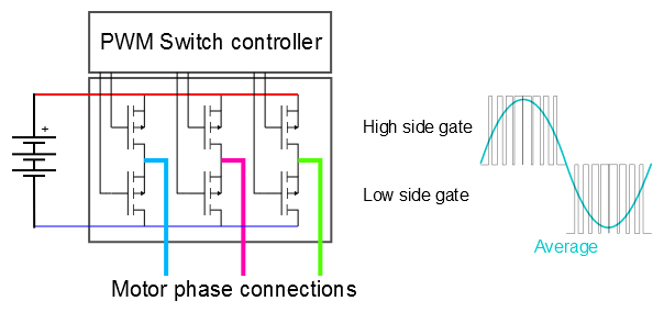
Now for some basic inverter theory. Inverters take DC from a battery or other source and turn it into an AC waveform, in this case, to drive the motor. How is it done? Using a couple of switching components to pull an output node high and low, this implementation is known as a H-bridge, we can generate a waveform by inputting a varying Pulse Width Modulated stream and averaging the output of the H-bridge. using three of these, one for each phase of the motor, a 3-phase relative waveform can be generated.This figure shows a typical 3-phase inverter configuration and a simplified illustration of how a waveform can be obtained by averaging a PWM stream.
![]()
The important advantage of using a pulse stream like this is that the switching components (for example FET's in the above figure) are kept either in a low-impedance ON state or high impedance OFF. They transition through the linear range of conduction as quickly as possible, this reduces loss in the switches.
With that basic theory out of the way, Lets move on to the physical inverter implementation.
Requirement 1 is primarily a matter of choosing appropriately specced components and having good PCB layout, since this is going to be a low cost, low weight system 48V motors are commonly available and this relatively high voltage keeps the system current low, reducing resistive loss.
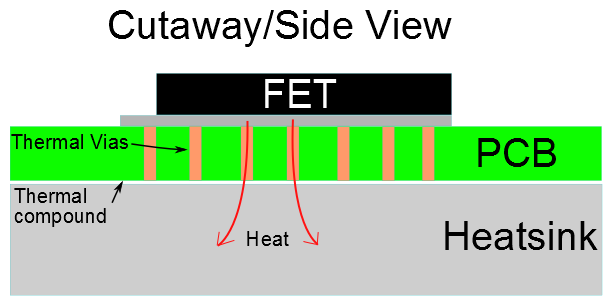
Requirement 2 and 3 can be achieved by using modern MOSFET technology, and switching them properly. we will use low Rds(on) FETs from NXP, after investigating many different manufacturers the NEXFETs from NXP seem to have the best gate charge vs Rdson - gate charge limits how quickly FET's can switch and Rds is the drain-source resistance that results in conductive losses when the device is fully on. The powerSO8 package also has excellent thermal characteristics and can be heatsunk through a viad PCB, making the layout very compact. Manufacturability is also improved over using TO220-style packages as the whole board can be made SMD then simply bolted onto a slab of aluminium as shown below:
![]()
To switch the mosfets we are using isolated gate drivers from Silabs. these chips are monsters. 4A current capability and 1000V isolation. probably overkill but we can cost reduce later ;) These will ensure the FET gates are transitioned in mere nanoseconds, wasting very little power in the linear region of the FET.
EverywhereElectric
Motor control/monitor system for a fully featured EV (bike, board, etc), >1KW 3phase motor control, Android control interface and hardware.