jurc192
-
Dusting off the CD-drive
01/19/2018 at 12:43 • 0 commentsAfter a wild December full of socialising, dancing, heavy drinking and other joys of student life, it's time to switch back to the "geek mode" again. Having my "Arduino to IDE" interface built and (more or less) understanding how it works from the hardware point of view, it is time to dive into the software again.
Where has the project stalled?As I mentioned before- what I am doing, has already been done by Carlos Durandal's ATAPIDUINO project. While I could simply upload his code (it works fine) and move on, I couldn't sleep without understanding how it works, what it does and why it works. Most of all I was wondering, how did he know what to do?
When I first tried to figure out how to communicate with CD-devices, I landed up in a mess of protocols, standards and various documents that had the right keywords, but I didn't understand shit there. What I did learn then was that ATAPI is the right thing to look for.
Then, I tought I could answer my question by looking at CD-drive Linux drivers. But it turned out to be too complicated, for a newbie like me, to learn anything useful from it. The functionality (e.g. CDROMEJECT) in linux drivers matched the functions described in various ATAPI documents and ATAPIDUINO, though. So it wasnt a total shot in the dark.
But this time, I am armed with a working interface, it's source code (atapiduino) and the right keywords in mind. I've decided to study ATAPIDUINO and compare it's working to the ATAPI standard. If everything matches, I've found the answer to my question- you can learn how to communicate with CD-drives, by reading the right standard.
What standard to choose?There are some people that tried to simplify and explain the mess of ATAPI standards, CD-drives and various implementations. I found the table in the wikipedia article useful, since it summarizes the development of the standard and it's features.

ATA development in a nutshell... I have decided to study the ATA/ATAPI-4 standard, since it was the first to introduce the packet interface and the first to mention the CD-drives. I guess it contains all the fundamentals and doesn't include any special-fancy-features that were added later, which I don't need in this project. The standard is written by the T13 Technical Committee, which is a part of the NCITS, which is...whatever. Something that sounds like a big and scary round table of engineers, corporates and politicians trying to destroy the world, hah.
Did you know? The T13 Technical Commitee has a website with a list of all the standards, working drafts, documents etc. It looks precious. You can even choose between PDF, DOCX etc. The only problem is, you can't. It's just a text, not a download link! Even for working drafts. And by the way- why do you have to pay, to see a standard?!

T13 Technical Committee webpage, where are standards are available...NOT
Where to start reading?When you open the ATAPI standard, don't be like me and try reading it from the beginning- you will fall asleep immediately. Table of Contents is your friend :)
I would say that the most interesting chapter to begin with is [ATAPI 5: Interface signal assignments and descriptions]. There you can read more about individual pin functions.
ATA/ATAPI-4 standard excerpt I then discovered that there are two ways to communicate with an ATAPI device [ATAPI 6.1: Command delivery]. One way is via writing directly to interface's registers and the other way is to send packets. Before diving into this, let's make one thing clear: what are registers?
Learning about registersFor dummies (like me)- registers are "things" that store bits. Usually they contain 8-bits (a byte) or 16-bits etc. Each individual bit, has it's own meaning. For example, if my CD-drive only had one register with 8 bits, one bit would control the CD-tray. Setting this bit to 1, would open the CD-tray and clearing the bit to 0 would close it. I learned something about ATAPI registers in this guide.

An example of a register There are 9 registers used in CD-drives (there are more, but not used). Some of them have two names, depending on whether you are reading from or writing to the device. According to the guide reading/writing to the registers works like this:
- Set the register address, by controlling the pins A0, A1, A2, ~CS0 and ~CS1. (In ATAPI standard they are reffered to as DA0, DA1, DA2).
- In case of writing to registers, write the desired command and it's parameters to the register (pins D0: D7).
- Set ~RD or ~RW low (= to assert), depending whether you want to read from or write to the register.
- Read the status register, to see if the operation was successful.
NOTE: In ATAPI standard there is a bit "weird" way of displaying register's address. Assert means to "activate" a pin (e.g. set it to 1). Negate means to "deactivate" a pin (e.g. set it to 0). This notation is used, because the CS0 and CS1 are active low. That said, to activate the pin you have to set it to 0 (low). Pins DA0-DA2 are "normal" or active high. So to activate them you set them to 1.
What I couldn't understand right away is that each register has it's own address, and it's "space" for bits. How ATAPI devices work is that you set the register's address and the device will "display" it's content in the data port (pins D7:D0).

Parts of a register and its connections to pins I now understand how communication to ATAPI devices (CD-drives) works, in general. I hope that my explanations makes someones life easier, as I spent quite a lot of time to understand this >.< I am wondering how much faster could I learn this, if I had an instructor or went to university class about this :)
What began as a software project log turned out to be more of a standards & registers log. Ewgh!
In the next project log, I'll describe my studies of ATAPIDUINO code and comparing it to the ATAPI standard. -
Hello schematics
11/26/2017 at 15:10 • 0 commentsI always tought electronic schematics look cool. Finally I did my first - to make the messy sketch of my first circuit more clear. I couldn't decide between KiCad (as a FOSS fan it would be my first choice, but it looked a bit awkward judging from the reviews), EAGLE or Altium. I did it with EasyEDA in the end :)
[Link to PDF version of the schematic]

Arduino to IDE Interface schematic I was trying to think of readability, functionality and aesthethics. I would like to know some more principles of schematic design, are there any mistakes? What would be the "appropriate" way to do it? Is there something not really conventional? How would a professional draw it?
Any easyEDA users out there? Should I use some other tools (like KiCad, Altium, Eagle..) instead? Why?
-
Building the interface v0.1
11/21/2017 at 13:15 • 0 commentsIt's finally time to build this interface and move to the software part! After messing around with PCF8574 I/O expanders a little bit, I build the arduino -> IDE interface.
I was mostly reffering to Carlos Durandall's ATAPIDUINO scheme, ommiting stuff I didn't understand or think was important.I tried to redraw and simplify Carlo's schematic, but ended up with even messier one and gave up. I'll do it properly in the next phase, to print PCBs (because this trough-hole stuff was a pain in the ass to do).

My pathetic attempt to make the schematic prettier I decided it's better to just write what goes where (included at the end of this log).
After hooours of planning, wire stripping and soldering it was done. AND IT WORKS! :D
I used an old ATX power supply to power the board and the CD-drive. I also used DIP IC socket adapters just in case I'd fry one of the I/O chips, and I used Arduino Nano.
Controller board from an old CD-drive - wanted to get the IDE connector off 
Desoldering the IDE connector - using soldering iron, solder suction pump and a flat screwdriver... 
Desoldered 40-pin IDE connector - finally! 
Finished board, bottom (almost finished, messed up the red power supply wire at the molex connector) ")
Finished set-up (without the IDE cable connected) 
Playing the CD, listening from the audio output in the front panel, controlling the drive via serial terminal on a PC What goes where?
ARDUINO:
Arduino A5 (SCL) ---> 47kOhm resistor (pull-up) ---> + 5V
Arduino A5 (SCL) ---> PCF8574 pin 14 (SCL) (TO EACH PCF!)Arduino A4 (SDA) ---> 47kOhm resistor (pull-up) ---> + 5V
Arduino A4 (SDA) ---> PCF8754 pin 15 (SDA) (TO EACH PCF!)Arduino Vin ---> + 12V
Arduino GND ----> GNDEach I/O expander has it's own address to distinguish between them, I'll call them PCF#1, PCF#2 and
PCF#3 (addresses 0x20, 0x21 and 0x21 respectively).PCF#1:
Address is 0x20pin 16 (VCC) ---> +5 V
pin 8 (GND) ---> GNDpin 1 (A0) ---> GND
pin 2 (A1) ---> GND
pin 3 (A2) ---> GNDpin 13 (INT) ---> N.C. (not connected anywhere)
pin 4 (P0) ---> IDE pin 17 (D0 also DD0 or Data0)
pin 5 (P1) ---> IDE pin 15 (DD1)
pin 6 (P2) ---> IDE pin 13 (DD2)
pin 7 (P3) ---> IDE pin 11 (DD3)
pin 9 (P4) ---> IDE pin 9 (DD4)
pin 10 (P5) ---> IDE pin 7 (DD5)
pin 11 (P6) ---> IDE pin 5 (DD6)
pin 12 (P7) ---> IDE pin 3 (DD7)PCF#2:
Address is 0x21pin 16 (VCC) ---> +5 V
pin 8 (GND) ---> GNDpin 1 (A0) ---> GND
pin 2 (A1) ---> GND
pin 3 (A2) ---> GNDpin 13 (INT) ---> N.C. (not connected anywhere)
pin 4 (P0) ---> IDE pin 4 (DD8)
pin 5 (P1) ---> IDE pin 6 (DD9)
pin 6 (P2) ---> IDE pin 8 (DD10)
pin 7 (P3) ---> IDE pin 10 (DD11)
pin 9 (P4) ---> IDE pin 12 (DD12)
pin 10 (P5) ---> IDE pin 14 (DD13)
pin 11 (P6) ---> IDE pin 16 (DD14)
pin 12 (P7) ---> IDE pin 18 (DD15)PCF#3:
Address is 0x22pin 16 (VCC) ---> +5 V
pin 8 (GND) ---> GNDpin 1 (A0) ---> GND
pin 2 (A1) ---> GND
pin 3 (A2) ---> GNDpin 13 (INT) ---> N.C. (not connected anywhere)
pin 4 (P0) ---> IDE pin 35 (A0)
pin 5 (P1) ---> IDE pin 33 (A1)
pin 6 (P2) ---> IDE pin 36 (A2)
pin 7 (P3) ---> IDE pin 37 (CS0)
pin 9 (P4) ---> IDE pin 38 (CS1)
pin 10 (P5) ---> IDE pin 1 (RST also nRST)
pin 11 (P6) ---> IDE pin 23 (nDIOW)
pin 12 (P7) ---> IDE pin 25 (nDIOR)So now I can play around with CD-drives and give them various commands and see what happens, sweet! Oh and for the arduino code, I used ATAPIDUINO's sketch R1.0. I didn't have physical buttons in my design yet, so I changed the button controls to Serial.read() commands.
Next step I want to do is play around a little, see if the circuit works and if it does - make a proper schematic and print a PCB.
-
First productive steps
11/21/2017 at 12:00 • 0 commentsI figured out that my theory-based approach (with lots of spec reading and basic tutorials) won't get the CD-player going. And people have been trough all this before me, so why reinvent the weel.
There was a bookmark in my browser, that contains most of the answers to my previous questions - ATAPIDUINO (by Carlos Durandal). How could I forget about this! I wanted to know and understand things, before moving to this already-finished arduino project. But how could that be better than studying an already working example *facepalm*!
Serial to Parallel conversion magic box
How do I connect Arduino to a 40-pin IDE connector? Connecting every arduino pin directly to IDE pin wouldn't work, I should rather do somekind of serial - parallel conversion (introduction to the topic). And that exactly what Atapiduino does, using I/O expanders for I2C bus (PCF8574).The PCF8574 I/O expander basically recieves bits one-by-one and when it collects a byte (8 bits) it "spits them out" simultaneously, each bit on it's own pin (rough description, probably not technically correct/exact).
We send commands from a microcontroller (Arduino) to PCF8574 I/O expanders using I2C protocol (lots of good tutorials about I2C on yt and google).I first tried connecting an I/O expander to an arduino and a LED, to learn how to work with theese.


Only thing you have to set before toggling pins on/off is the address of the device- datasheet (chapter 7 my case) describes this well. And the I2C serial communication things like start & stop bits, parity, baud rate etc. - you don't have to worry about theese, if you use arduino. The Wire.h library handles all this, so all you have to do is begin communication, set the address of the slave device (the I/O expander is slave, arduino is master) and start sending bytes.
#include <Wire.h>

void setup() {

  // Start I2C interface
  Wire.begin();

  // Set parameters for communication with our PCF8574 I/O expander.
  // We've set all the address pins (A0, A1, A2) low,
  // so our I/O address is 0x20h according to the datasheet.
  Wire.beginTransmission(0x20);

  // Byte we want to send. Bits are mapped to pins P0 -> P7
  // (each pin represents one bit of a byte).
  // E.g. 0x07 (0b00000111) sets pins P0, P1, P2 HIGH and others LOW.
  Wire.write(0x07);

  // Transmit / send the byte
  Wire.endTransmission();

}

void loop() {
}
You can test if your circuit works, by measuring voltage on the P0->P7 pins of the I/O expander (one voltmeter probe to GND and another to one of the P0->P7 pins). For our example P0, P1 and P2 should be HIGH (5V), others LOW (0V).
I was struggling with my I/O chip for hours, only to realize that it didn't work. So be aware that ebay stuff sometimes doesn't work (lesson learned the hard way). Yay :)
Any electrical engineer wants to comment the use of PCF8574 in this application? If you had to connect a microcontroller to a 40-pin IDE device, what would you use? What would be the simplest component to use in this application? What would they teach you in school? Which chip would they use in industry? -
Digging deep inside Linux drivers
09/10/2017 at 21:46 • 0 commentsMy theory is: if my computer is communicating to the CD drive, so can I. And thanks to the free & open source community, I can see how "he" does it.
I guess reading about some kind of Linux CD drivers would be a good start. I refreshed my C programming language knowledge, by writing some simple programs and started reading about Linux kernel and drivers. It was a huge and interesting "detour", but had nothing to do with this project. Crap!
One of the simplest task I could think of was to eject the cd tray. Thanks to this awesome Introduction to the Linux CDROM Interface it was done in no time.
/* eject.c
** Copyright Paul Dwerryhouse, 1997-2004
*/
#include <sys/types.h>
#include <sys/ioctl.h>
#include <fcntl.h>
#include <linux/cdrom.h>
#define CDDEVICE "/dev/cdrom"           /* CDROM device */
int main(int argc,char **argv)
{
   int cdrom;                           /* CDROM device file descriptor */
   /* Open the CDROM device. The linux/cdrom.h header file specifies that
   ** it must be given the O_NONBLOCK flag when opening. My tests showed
   ** that if this isn't done, this program will not work.
   */
   if ((cdrom = open(CDDEVICE,O_RDONLY | O_NONBLOCK)) < 0) {
        perror("open");
        exit(1);
   }
   /* Use ioctl to send the CDROMEJECT command to the device
   */
   if (ioctl(cdrom,CDROMEJECT,0)<0) {
        perror("ioctl");
        exit(1);
   }
   close(cdrom);
}
The main things here are ioctl and the cdrom header file.
IOCTL (Input Output ConTroL) is "a kind of device-specific system call". Every device has it's own ioctl commands. Longer explanation is in "The Linux Kernel Module Programming Guide".
And the cdrom header file can be found in /usr/include/linux/cdrom.h . It contains commands and definitions for accessing CD-drive. I got mine from Linus Torvald's github - linux kernel source tree. Actually there are two cdrom.h files in the kernel source. The one I found (more) useful is in /include/uapi/linux/cdrom.h and the other one is in /include/linux/cdrom.h . Confusing at first, but here's the answer why.
My friend Otto joined me, and we tried sending various ioctl commands. Sending CDROMSTART and CDROMSTOP commands was succesfull, but we couldn't tell what they are doing. Commands CDROM-PAUSE or -PLAYMSF for example didn't work on our device -> ioctl: operation not supported.
Command CDROMSUBCHNL (read sub-channel data) was interesting, since it outputs "current" track, minute, second and frame (1sec = 75 frames).
After playing a song from cd and stopping (and exiting the audio program) the same command gave different results. Exactly where we stopped the playback.Next challenge was to read audio from the CD. We're guessing that -PLAYTRKIND (Play track / index addressing) and -PLAYMSF (Play track / minute-second-frame addresing) refer to playing audio from those analog audio outputs on the CD-drives themselves. Because those operations were not supported on our modern CD-drive without analog audio output.
Anyway, we got to read the audio with -READAUDIO command!
We put the returned output to a file (.wav) and played that with aplay cmd audio player. Btw the flag -f cd gives you the correct output, but playnig around with different bitrate and channel number might produce funny results.After playing around we tried to go one level deeper into the kernel. I really wanted to get to the switch statement that would recieve those CDROM-xy commands we send via ioctl function. Well, it wasn't easy to find it but it is in [kernel source]/drivers/cdrom/cdrom.c at line 3331. We followed function calls a bit more, but soon we got lost in all the files and stopped at this point.
switch (cmd) {
    case CDROMMULTISESSION:
        return cdrom_ioctl_multisession(cdi, argp);
    case CDROMEJECT:
        return cdrom_ioctl_eject(cdi);
    case CDROMCLOSETRAY:
        return cdrom_ioctl_closetray(cdi);
    case CDROMEJECT_SW:
        return cdrom_ioctl_eject_sw(cdi, arg);
// And so on...
I guess finding information about the cd-drive controls from linux drivers was not a very productive idea. But it was fun and we learned a lot, studying and reading the linux kernel.
-
What language does it speak?
08/21/2017 at 22:23 • 0 commentsDiving into the wikipedia page, I learned that I can forget the name "IDE" (Integrated Drive Electronics) and think about "ATA" (AT - Attachment, from IBM's computer called AT).
![]()
There are different versions of ATA standard, each adding/changing some features and having it's own name. For this project we will need to read about "ATAPI" (AT Packet Interface). I tried to find some more tangible information on how to program it, starting with those wikipedia references. After scrolling briefely trough pages of ATA standard evolution, I came across a page named: "Making Sense of IDE/ATA Standards and Compatibility". Well...even that didn't help that much :(
After drowning in all this protocols and things, I decided I'll try something else. My computer has a cd-drive, and I have linux OS. This means that I can read the source code. So in theory (!!!) I could find out which commands my computer sends to the CD drive. I know, I know, there might be a faster or more direct way of getting to this info, but since I like messing with linux, drivers and low level stuff in general- why not? :)
-
A dive into the CD - drive
08/21/2017 at 19:38 • 0 commentsI started with exploring my CD - drive. How does it work, how do I control it and what does it output?
The "how does it work" part you can find easily, if you know how to open google and search for it. I won't go into this here.
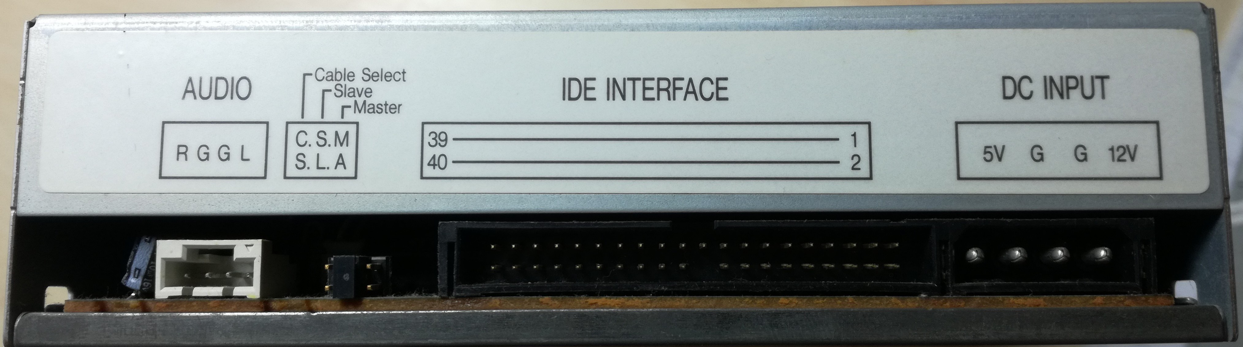
Next step for me was reading all there is to read on the housing of my CD-drive. I was happy to see that the model I have, is so well labeled- all the connectors on the back are labeled with words. I don't see such effort in newer devices so often.![]()
1. POWER SUPPLY
Powering the drive is quite straight-forward (thanks to all the labels and stickers). In my case it says: "POWER SUPPLY DC 5V 1.5A / 12V 1.5A" .Now, for the connector (labelled "DC INPUT") couldn't find a better answer than: MOLEX. As you might see "Molex" isn't one specific model of connector, but tons of them- crap! According to their webpage, the keyword that takes you one step closer to your CD- (and hard-, and floppy-) drive is "8981-series". That's good enough for me, for now. You can scavenge some of them from your old computer's (ATX) power supply!
Thing about the power supply that bothered me was: do I need both 12V and 5V supplies? Shouldn't only one be enough? After some reading on forums, I found out that you DO need both. One for the motors and "heavy weight stuff", other for the control circuit, chips and stuff. Having two separate power supplies looks a bit gipsy-ish solution, so I will try to find more elegant solution later. Any Electrical Engineers with an advice here? :)2. AUDIO CONNECTOR
I noticed that there already is an audio output connector (link). And some of my CD - drives even have two of them, digital and analog one. This means I could hook an amplifier directly to the drive, without having to deal with digital to analog conversion (the part which I'm "afraid" the most - have the least knowledge) -yay! :D
3. SLAVES AND MASTERS CONNECTOR
There is a connector that enables you to switch the CD drive between submissive-mode and master-dominating-your-life-mode...or something?
It's actually a connector for setting "Master" or "Slave" mode of the device (computers IDE controller needs to know this). Afaik it's there for historical reasons and since I only have one device, "Master" mode should work fine.4. IDE INTERFACE
Now the big connector...and the big knowledge gap for me. The IDE interface connector. You know you're entering the messy world of standards and protocols when googling "IDE interface" first takes you to "Parallel ATA" wiki. What? And it is a loooong page, full of history.
Before diving into it: IDE interface connector is used for connecting the drive with the computer's motherboard. It's an interface, for sure. And at the moment I only know that sending the right signals to the right pins (from Arduino, for example), will control my CD-drive. Yay! Also, IDE controller is an interesting keyword.
But what "language" does it speak? What bits do I need to send to which pins to open the cd-tray for example, or to skip a song? I guess I'll have to find info about some protocols...
-
Hello World!
06/02/2017 at 11:41 • 0 commentsI got this idea of transforming an old CD-drive to a music player when I was tearing apart an old computer. So much fun! But will I ever actually use any of theese salvaged components? After they gathered dust for few months it was time to either trow everything away or start making things out of them. I think this youtube video was first time I saw this kind of CD-player.
I know that my device has to:
- communicate with the CD-drive (to send commands such as play, stop, next ect. and to read data from CDs)
- control user interface (physical buttons, maybe also a display)
- convert digital data to audio signal

The diagram above shows general parts that I need to study and connect in order to get my old CD's playing. (One of the first (original) CD's I ever got, was "Soundtrack to your Escape" by In Flames. I got it for santa when I was about 11, hah :)
Using old CD-drive as a music player
Trying to build a simple CD-player from an old CD-drive. I want it to read audio CDs, have button controls and an audio output.


")