I somewhat left this project in the dark for some time now, since I focused on other things and didn't had spare financial resources to invest in this. While quarantined due to COVID19 I thought about this project again and realized I never updated the project to show off my hardware design.
I actually had the hardware design complete already, which was the result of much consideration into many issues: aesthetics (not too big, not too small, good screen to device size ratio), ergonomics (I even chose tact buttons without low force, incredible that you can select this level of detail when choosing components), usability (comfortable orientation of buttons, how would the device be mounted to the bicycle) and other things.
Besides the aforementioned reasons for putting this project off, was the fact that there was an important part (the accelerometer + compass IC) that was out of stock. I waited for some weeks and it would never be restocked. Even now after many months later, it is STILL out of stock and my guess it will be discontinued. So, I decided to lookup for a replacement and to my amazement I found one similarly priced, with similar power consumption and even featuring a gyro aswell. Also, by looking at another project which also featured the Sharp Memory LCD and tried to be very low power, I found they used a nice linear regulator very VERY low quiescent current of about 8uA. I'm not sure if I'm splitting hairs here, since I'm capable of having introduced a stupid mistake that would waste precious power, but at least this was not a difficult change.
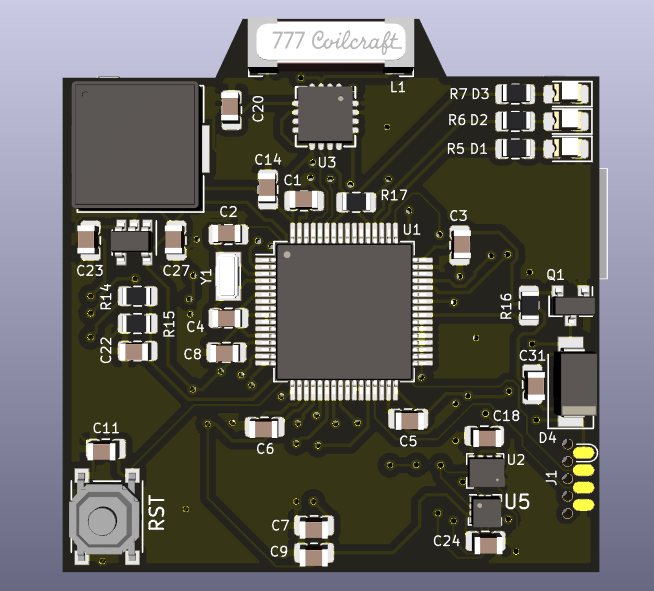
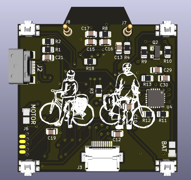
So, today I opened up the design in Kicad again, introduced these changes, put everything up on a git repo and made some pretty pictures (about time). So, behold the new BicycleCompanion:

On the other side you can see the four tact switches, a waterproof USB connector and the battery charging IC (U4). The bottom connector is for the Sharp Memory LCD display which would wrap the cable to the front (hopefully I didn't mess up the positioning and this will work OK). Finally, you can see the two POGO pins at the top, which allow to connect to the reed switch sensor mounted at the bicycle fork (which will sense a magnet installed in the wheel).

Finally, there are contact pads to solder a LiPo battery (which should fit at the bottom of the PCB) and a vibrating motor for haptic feedback, alarms, etc.
There is one caveat however: now after all this time it seems that the lightning IC seems to be discontinued =(
So I'm trying to think whether to remove it from the design (and remove the "hump" on top and have a square PCB) or leave it in place for now and see if it is restocked in the future. Don't know...
Anyways, I'm quite happy with the result and I would really like to have all parts and PCB already in order to get into the programming. However, due to the quarantine, limited funds and all the complications of importing stuff to Argentina, I'm not sure when will this happen. Hopefully sometime this year I can place an order and see if this thing works. It would be really cool to eventually carry it with me on a trip and really test it.
By the way: the hardware design is not yet public, but if there's interest I can publish it.
 Matias N.
Discussions
Become a Hackaday.io Member
Create an account to leave a comment. Already have an account? Log In.
Hi Matias, I think it should be nice if you release it as open-source license and also put the device for sale at Tindie. You went over all the process of building a product and it is really nice to read. Maybe you use github to host and and create some youtube video describing the process. It could be helpful for many people. Also it could be like a "visit card" for a job interview.
Are you sure? yes | no
Sure, once I get the design finished i will put it up on github. Same with the firmware later on. I also intend to certify it with OSHWA.
Once the Hackaday Prize opens I will probably try to present the idea better, stay tuned =)
When I get a few prototypes built I will put them on Tindie, but I'm not sure if the prize I could offer it will be worthwhile to others since it will probably be cheaper to buy the PCB and components directly instead of through me due to the high shipping cost I have. But that would be really cool indeed.
Are you sure? yes | no