-
BluePill and its annoyances
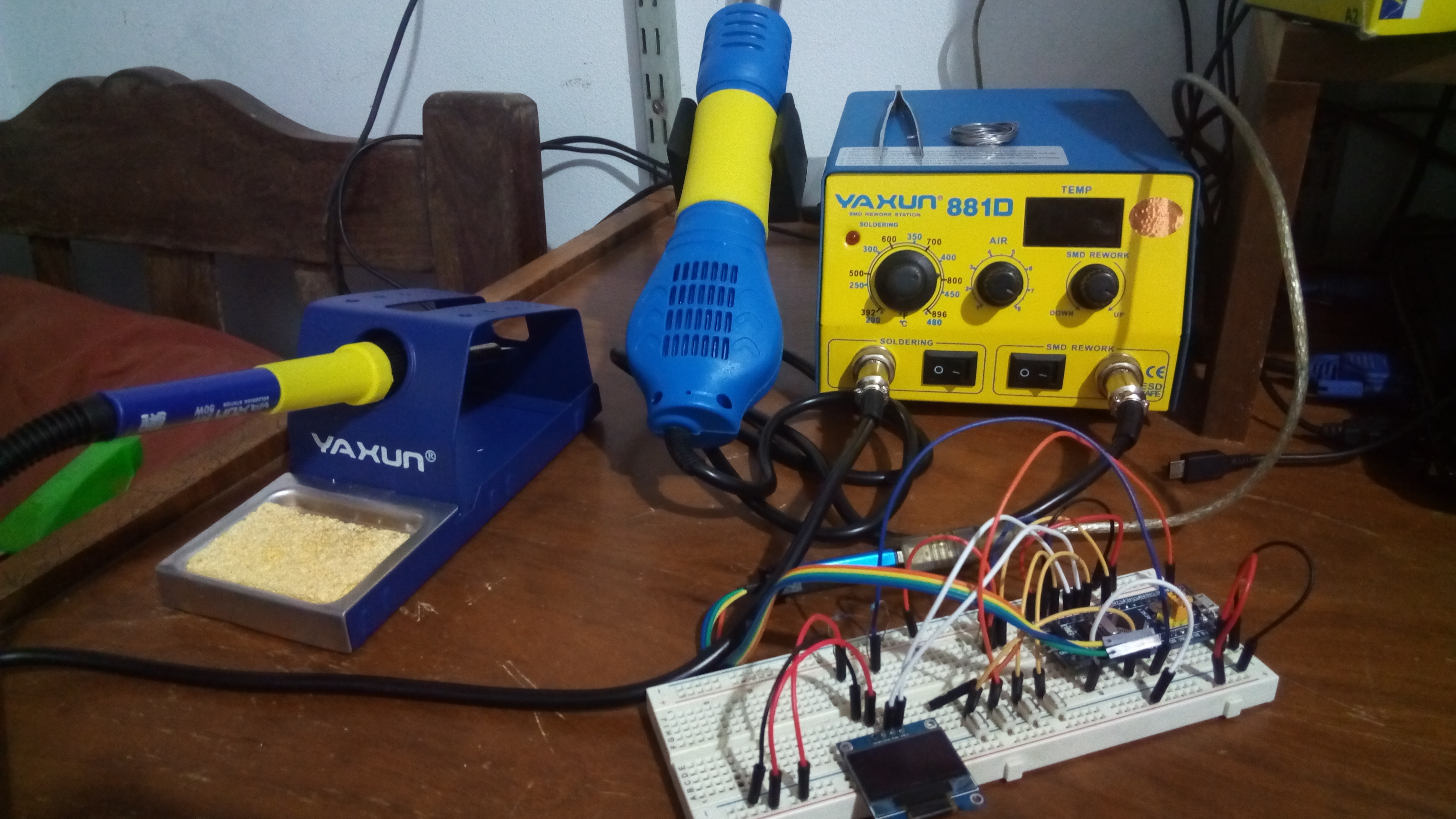
06/22/2017 at 01:44 • 2 commentsSo, some updates on the project so far. First, I received my nice new solder station. Second, I started porting the code to the BluePill (was previously using Teensy 3.1) in order to be closer to what the final device will be (as I will use same STM32F103C8T6 microcontroller).
A bit of surgery
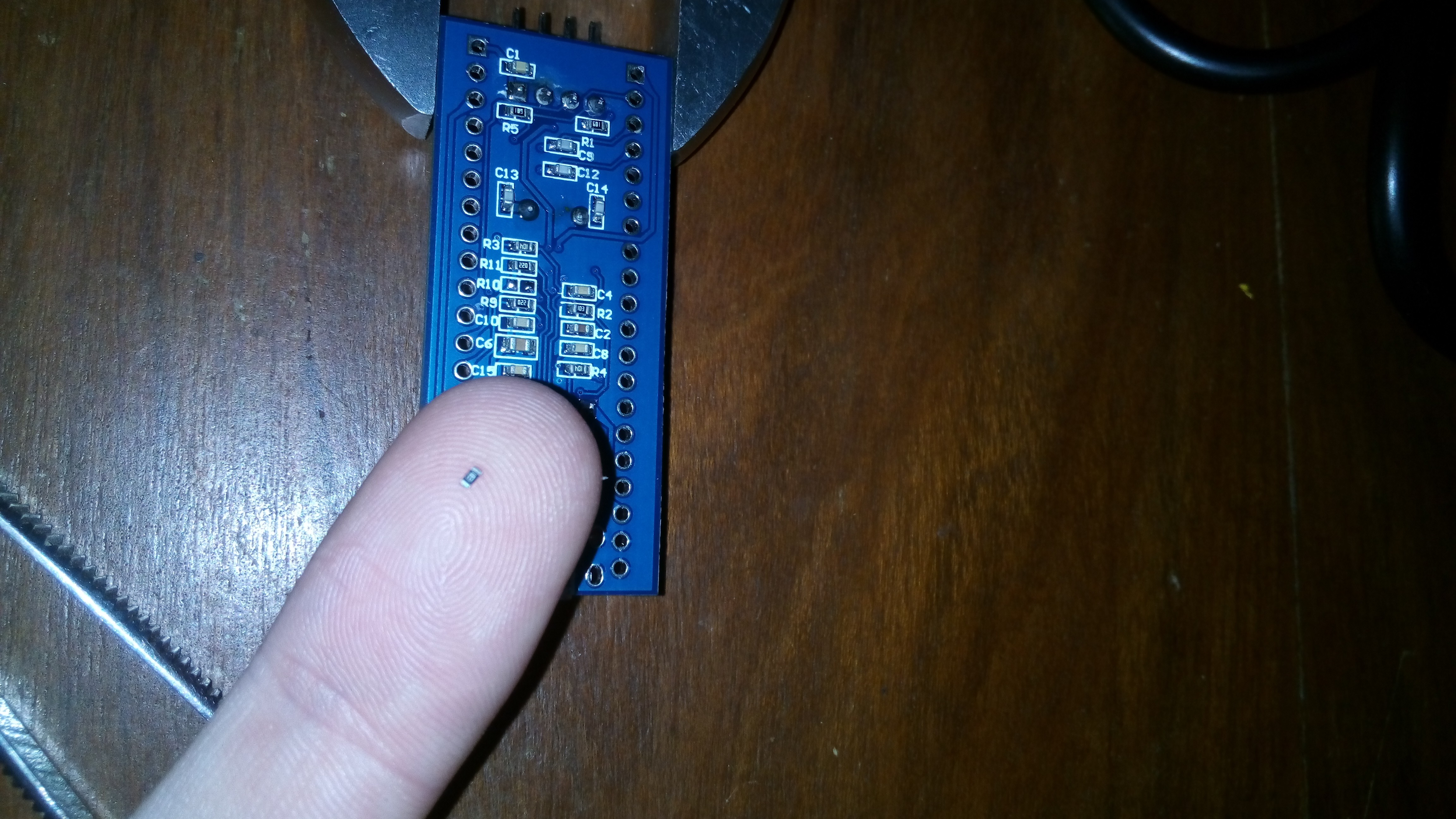
![]() The first thing I had to deal with using the BluePill is the wrong resistor on the USB D+ line. The board comes with a wrong resistor value of 10k, which should be actually 1.5k (pulled to 3.3v). Now, replacing a 0603 (I believe) resistor crammed between other resistors requires some work: a perfect opportunity to test the hot air of my station. After a few second under hot air (at around 300C), I managed to remove the resistor easily.
The first thing I had to deal with using the BluePill is the wrong resistor on the USB D+ line. The board comes with a wrong resistor value of 10k, which should be actually 1.5k (pulled to 3.3v). Now, replacing a 0603 (I believe) resistor crammed between other resistors requires some work: a perfect opportunity to test the hot air of my station. After a few second under hot air (at around 300C), I managed to remove the resistor easily. ![]()
On my finger is the resistor (R10 on the board). Yes, I'm using a french wrench as a ghetto vise. I then later soldered a 0805 resistor of the correct value, which luckily still fitted the original pads.
USB Bootloader
Now that USB supposedly worked, I tried flashing the USB bootloader (using the ST Link v2 programmer). Obviously this didn't work (the device would not enumerate on Linux when plugged). After several hours of searching and asking around in some forums, complaining that this did not work, I eventually found out the problem was actually a bad soldered USB connector. So, some flux and a pass of the solder and now I was getting some response from the board.
With the bootloader loaded I managed to flash the example blink program from within the Arduino IDE. So the second issue was to do this from platformio. This required fiddling a bit with board definition files since it seems a wrong linker script is chosen (you can see the issue here https://github.com/platformio/platform-ststm32/issues/38).
Also, I had to configure the board as being STM32F103CB (not C8) which allows me to use the whole 128KB of the flash which is present on most of C8 boards. I needed this since I'm already at 112KB on my code.
Fighting with Arduino Code
The final issue I had was with the change of board. I amusingly assumed that since Arduino is mostly standarized nowadays and since I was not using any really advanced or low level stuff the change from Teensy to STM32 should be more or less simple. Wrong.
The main problem is that the STM32 Arduino port is not as complete or carefully organized as Teensy core libraries. For example, by default Wire is actually software I2C and you actually need to use HardWire to use hardware I2C. This in turn implies that STM32 Arduino port includes many I2C libraries simply because they need to change Wire to HWire. Since these libraries are actually a bit old now, luckily I managed to make this change to my copy of a recent version of Adafruit's SSD1306 driver.
Another issue is the lack of printf in Print class, which affects SSD1306 driver. I had to resort to calling sprintf() using a local buffer, which was not that bad but a bit annoying.
In the end I managed to port most of the functionality I had with the exception of RTC. For some reason, when I enable the RTC (using the RTClock library which comes with STM32 Arduino) it hangs. It appears the 32k crystal is not oscilating. I'm not sure if there is (another) hardware issue or there's something missing. This is a bit worrisome since I copied this part of the circuit for my device so I hope it works in my case.
PCB changes
All this testing on the BluePill was actually good since I realized I had some design flaws on the PCB. First, I was not grounding the RTC cristal capacitors (ouch). Also, there are some pins which, when SWD is enabled, cannot be used since they are supposed to be used for JTAG. I was using these pins for reading buttons, so I switching pins. Also, I decided to wring back the user LED and tie it to PC13 to conform the BluePill. I think this will simplify any customization down the line.
What's next?
A few days ago I ordered some of the difficult SMD components, which should arrive in about a week. In the meantime I will probably go and buy the "easy" components (such as resistors, capacitors, etc). After I get all this I will verify the board design to see if footprints match. If so, I will send it for fabrication. This will probably give me some dead time which I will use to continue working on the code.
-
Porting to BluePill (STM32F103C8T6)
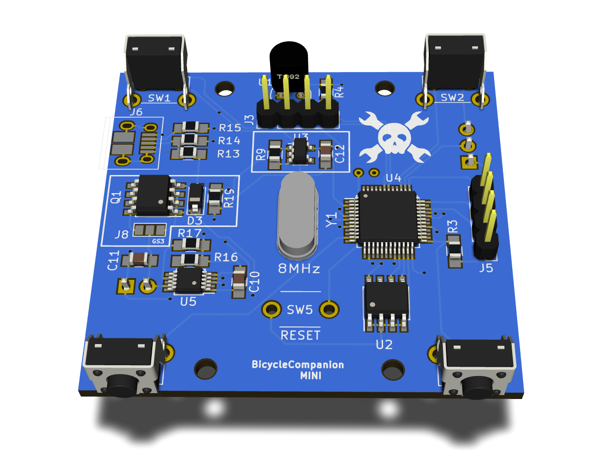
06/18/2017 at 21:45 • 0 commentsThe last weeks I haven't been advancing much since I was a bit busy. Also, I iterated the PCB design a bit more and simplified some things. I removed power and user led for minimal power use, remove UART port (not of much use if USB actually works as serial) and rearranged some things to be able to have four aligned mounting holes. At the moment, the board looks like this:
![]()
Dat hackaday logo ;)
You can see I'm still missing the USB 3D model (still waiting to decide if I will get the SMD version or not) and the reset button (which is now a two contact tact switch) for which Kicad does not have a 3D model.
Porting to BluePill
Now to the point of this log. While I was waiting for having the PCB ready and everything soldered to port the Teensy-based code to the STM32F103, I decided to give it a try on a BluePill board. After all, Arduino is pretty generic nowadays, right? Wrong.
I've found some annoyances and difficulties. First, since the BluePill comes without USB bootloader and, in fact, with a wrong pull-up resistor on the USB connector, I had to flash it via st-link. The problem was that after flashing the LED didn't blink and it would seem that afterwards it was kind of bricked. After much trying and browsing I realized that: a) the correct pin code for the LED is PC13, not 13! (so much for standarization) b) I had to define "CONFIG_MAPLE_MINI_NO_DISABLE_DEBUG=1" since otherwise the SWD pins were turned into GPIOs and thus it would not respond to st-link anymore. Fortunately, one can re-flash during reset so I managed to recover from this.
Once this was solved, I managed to upload a blink example and see it working. Now, I had to build and flash my code for this board. First problem was that several libraries I've been using were actually part of the Teensy platform package. I had to copy these (since they weren't actually Teensy specific) and place them directly along my code. Also, I had to find replacement for Teensy specific code, such as RTC handling code (which luckily seems to be there). Finally, I found out that TwoWire library is actually a bit-banged implementation of I2C! Luckily there is HardWire which can be used instead.
Once it started building correctly, I found a second problem: binary size was 112kb, above the 64Kb of the STM32F103C8 flash. I tried to reduce it but it does not seem possible. On the other hand, I knew that these line of chips are supposed to actually have 128kb. So, I configured the board in platformio as being STM32F103CB not C8, which has 128kb officially. Also, I had to download a recent version of st-link utilities which allow to override the flash size. While platformio does not support setting this flag, I could flash it manually once the firmware is built.
And FINALLY I managed to flash it and it was running. I also verified (by reading the firmware back) that there were actually more than 64Kb of flash there and indeed it was.
Next steps
So, now that it at least runs I need to repeat the test on the breadboard to test basic functionality on the BluePill. To do so, I still need to fix the USB pull-up and solder the header pins. For this, I'm actually waiting on a nice solder station (with hot air) I just bought and should be getting tomorrow from the post-office.
I've also already ordered some of the SMD components I needed for the PCB which should arrive in about a week. I will also need to go to the electronics store and buy all remaining components.
I'm planning on finishing the breadboard test before finalizing the PCB design. Also, I would like to print the design to ensure all footprints are correct w.r.t. to the components I'm getting. After that, I will send it for fabrication.
-
PCB Designed
06/05/2017 at 02:27 • 0 commentsIn the last days I've been playing a bit more with the code using the Teensy 3.1 based prototype. While there are still many things to be done on the software side, I decided I wanted to design the board based on STM32F108CT6 since it seemed more fun.
Last week I ordered a Blue Pill board but it seems stuck in the mail so I gave the PCB design a try. In the end, I learn many things and included many components I was considering initially but was unsure to include in the first version or not. I finally designed the PCB with all these included since I realized I didn't really need to include solder them all at once to start testing it since many things are quite "modular".
After finishing the schematic, which was not really that hard I went on to the PCB layout, which took me quite a while. I think that while the traces are a bit of a mess I didn't want to be overly perfectionist and simply finish it. I'd rather learn from a failed attempt than not do anything at all.
I must say I'm quite happy about it and, most importantly, it looks good =)
I think I will source some of the basic components first and then print this in a sheet of paper and check that all footprints match. After that, I will try and send it for fabrication to a local company (which I think actually fabricates using some Chinese company, and thus it can take about a month).
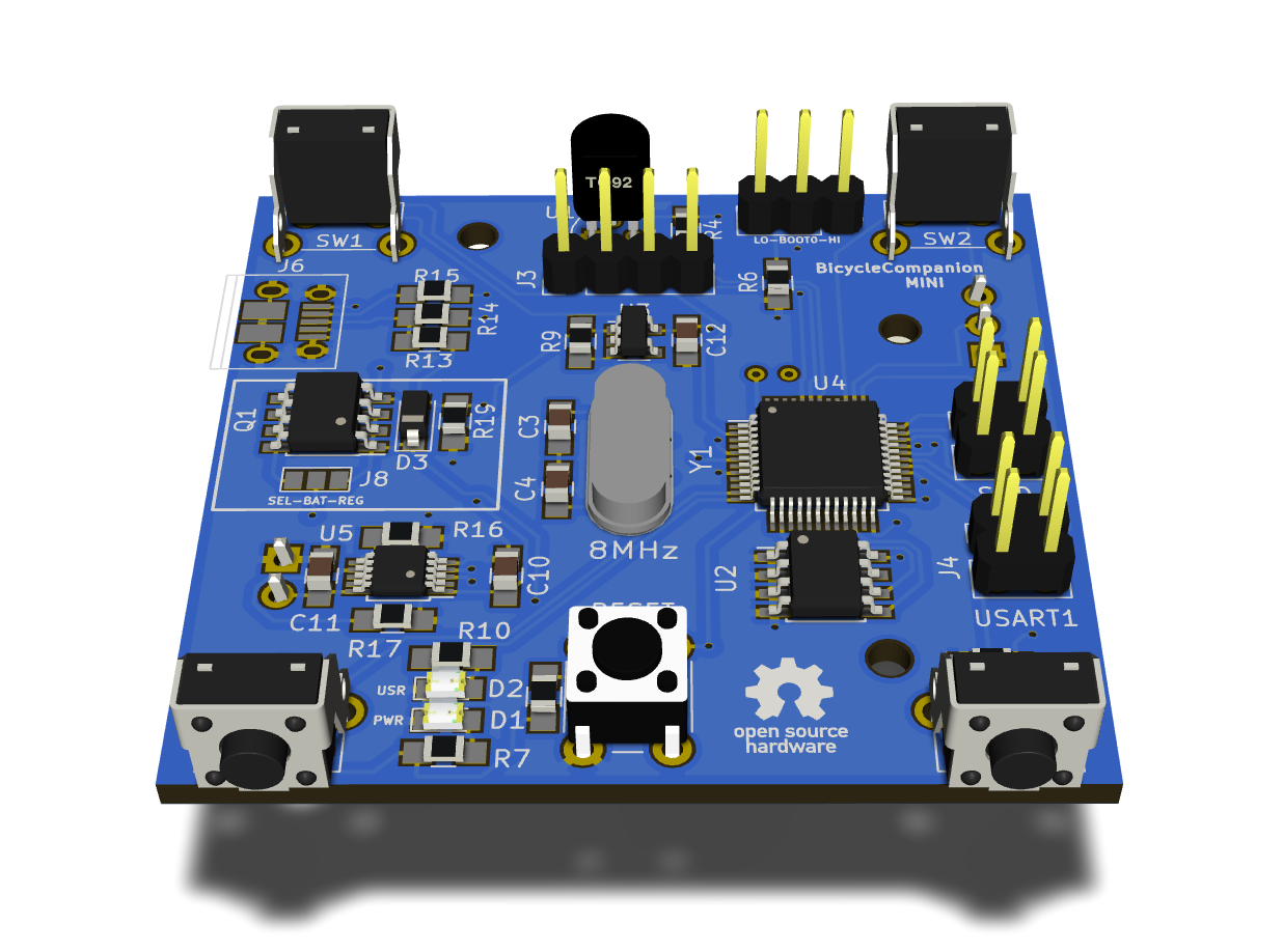
![]()
PS: I couldn't find a compatible 3D shape for the micro-usb connector. And I think the one I would get does not have those two ground pads some I may have to change that later.
-
Random considerations
05/31/2017 at 22:31 • 0 commentsSince I can't advance mucj during the week (yeah, work) I've took the time to learn about some things which relate to the project.
Font rendering quality
I've been using Adafruit's GFX library for rendering fonts on the SSD1306 and I was really disappointed by the rendering quality of self converted TTF fonts. It seems that it isn't so easy to convert vector fonts to bitmap and expect them to look nice on 1 bit displays.
When I used NuttX I had a better experience with don't rendering and I realized it used bitmap fonts, which are generally hand made and thus look really nice on these kind of displays. There are several formats for bitmap fonts such as PCF. The nice thing is that freetype library can read it and thus I could use the same fin convert utility from Adafruit. When I get the chance I'll test it but I suspect it will look much better.
Battery re-charging and permanent settings storage
I started with the idea to leave out battery re-charging in the device since I couldn't find any SMD ICs locally for that and did not want to include Chinese modules to the PCB. This meant that I would loose settings on the device when taking battery out for re-charging.
Since the STM32F103 does not have EEPROM un thinking on adding a cheap I2C or SPI chip for that.
However, I found a local distributor which has many nice SMD components and found that it sells several re-charging ICs. Among those, I found the MAX1555 and MCP73834.
Thus, in trying to decide if it would be worth to add this feature after all.
If anyone has any opinion about that, it is welcome.
-
Good progress
05/28/2017 at 18:38 • 0 commentsIn contrast to my original BicycleCompanion project, this time I made progress much faster.
The main difference is that in this case I decided to go back to the original approach of using Arduino famework. On the original project I actually switched to using NuttX which was a bit overkill for a project like this (at least, initially).
Another good thing is that I started using PlatformIO. Since I really hated the Arduino IDE but liked the existing libraries this was the perfect choice. I even can use QtCreator as the IDE. I used some existing libraries to base this: Adafruit SSD1306, Button, MenuSystem and Metro. This has made everything much simpler.
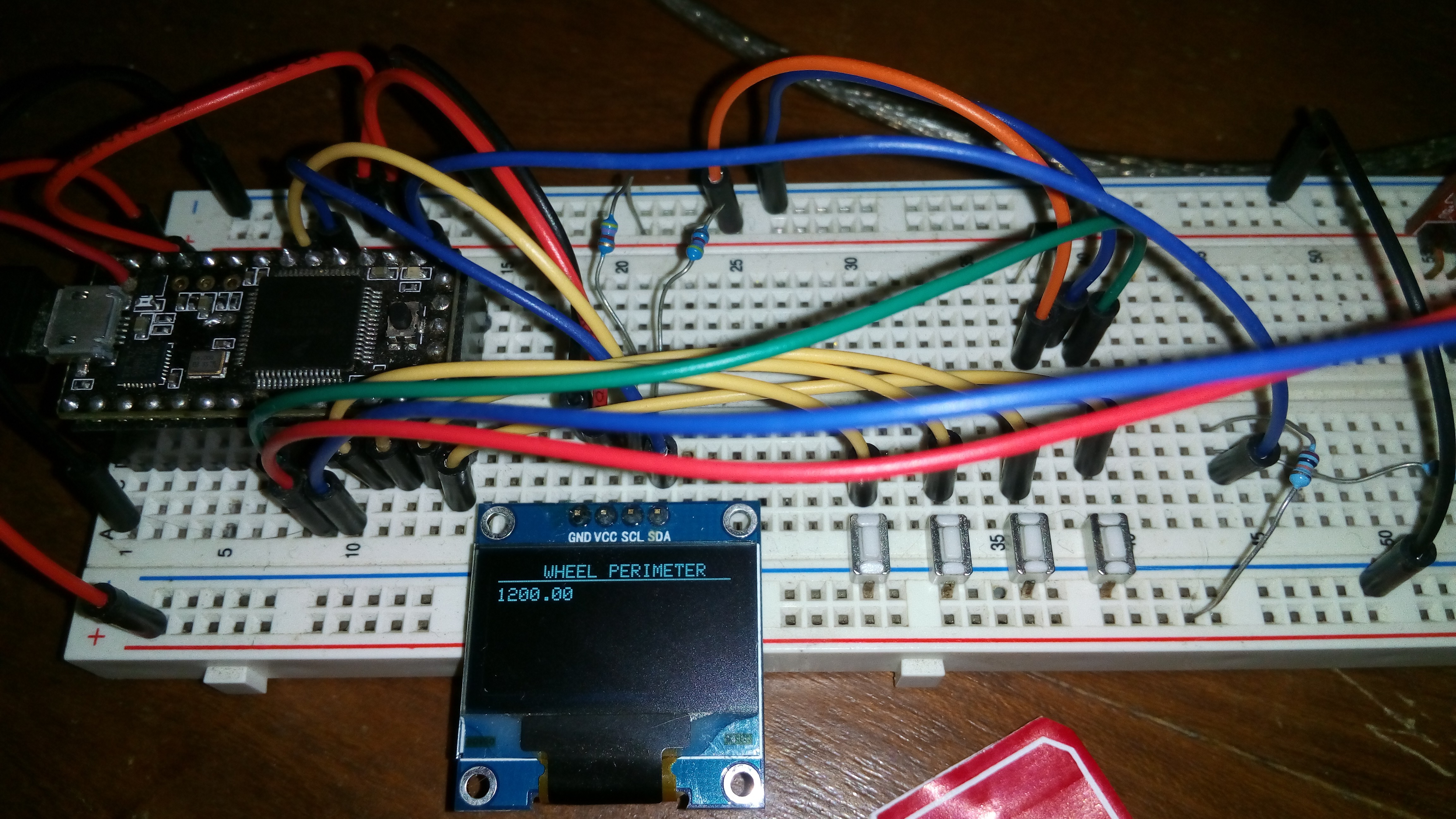
So far I have the main screens in place (some of which are stubs) which can be browsed with two of the four buttons. These screens are: current speed, traveled distance, moving time, current time, battery level and temperature. Each of this screens will have alternative views which can be browsed with the two remaining buttons. For example, different ways of looking at the speed, distance and so on, or browsing maximum, average stats of each. This is not yet made but will be.
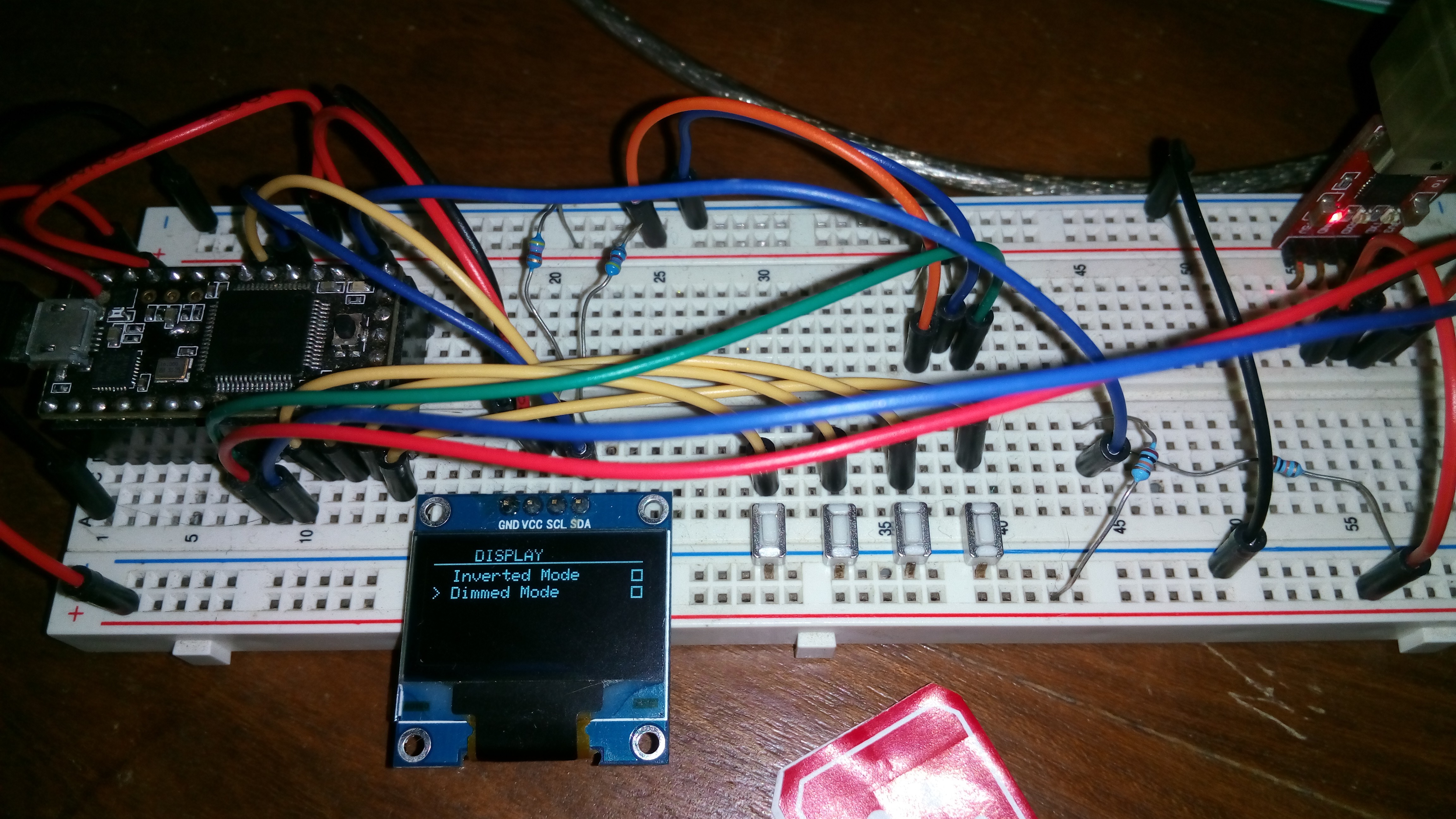
The part which required more work is the configuration. While I used the great MenuSystem library, having this being nicely rendered on the SSD1306 required a bit of thinking. In the end it looked quite nice (with that Sci-Fi 80s look I love).
The functionality so far is:
- Speed in KM/h from reading Hall sensor (using interrupts), which also accumulates traveled distance
- Current time and date display from RTC
- Temperature screen stub (this will be finalized using the reading of the actual DS18B20 sensor)
- Battery charge: reads supply voltage and converts it to a charge percentage (assuming single LiPo cell)
- Configuration menu allowing to change different settings:
- Wheel perimeter
- Exit config menu if motion is detected
- Time & date setting (not yet finished)
- Powersaving (screen sleep time)
- Display settings (inverted mode for higher contrast, dimmed mode for less battery use
Since I decided not to include battery charging circuit for simplicity for now, I realized it would be imperative to use permanent storage for settings. Since the STM32F103 does not have internal EEPROM (ouch), I need to include an external EEPROM chip for that. Luckily they are cheap and easy to use.
At the moment I've done all this on a Teensy 3.1 since I had it available for the original project. The next step is thus run the code on a Blue Pill board for testing. Also, I will add the temperature sensor and EEPROM chip.
After that I will probably start testing battery life and look into using Sleep modes to reduce battery usage to minimum (with such a device, most of the time it does not need to do much).
Finally, I plan to design a PCB and sent it for fabrication and try to solder everything myself (will see how it goes with all SMD components). I still have to decide whether to include a USB port for programming or use the SWD interface.
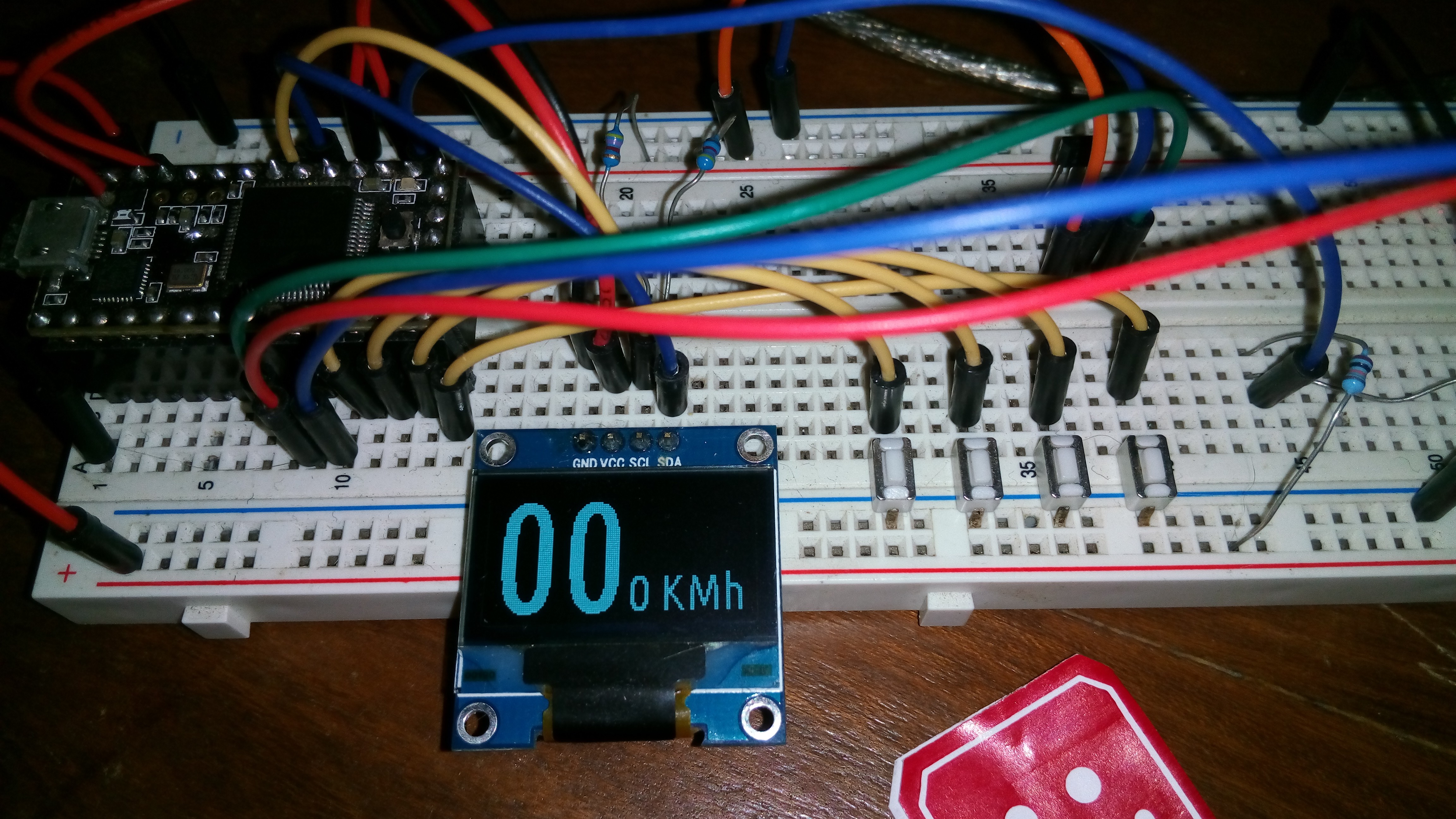
Here you can see some picture of how the user interface looks so far (will probably look better in the future):
![]()
![]()
![]()
BicycleCompanion
A modern, low-power and hackable cycling computer designed for bicycle-touring
 Matias N.
 The first thing I had to deal with using the BluePill is the wrong resistor on the USB D+ line. The board comes with a wrong resistor value of 10k, which should be actually 1.5k (pulled to 3.3v). Now, replacing a 0603 (I believe) resistor crammed between other resistors requires some work: a perfect opportunity to test the hot air of my station. After a few second under hot air (at around 300C), I managed to remove the resistor easily.