Close
0%
0%

How to repair any VFD

How to troubleshoot and repair any variable frequency drive.

Similar projects worth following
I am an service engineer and with this post, I would like to help people, trough some example, how they can repair variable frequency drives.

The basic:

At first I would like you to understand, what is the main parts of a VFD.
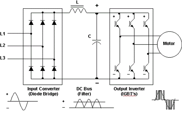
On the picture you can see a variable frequency drive power section diagram, with the main parts.

  1. The first is the bridge rectifier diodes. You see 4 diodes if your device is require one phase, or 6 diodes if it require 3 phase input.
  2. In the middle you see an inductor and a condensator for smoothing both the voltage and the current. It is called "DC - bus"
  3. On the right side of the picture, you can see the 3 phase IGBT bridge. The bridge contains 6 high power IGBTs.

Start the repair

At first you shoud not want to power up the drive, without you actualy measured the power section! If you power up the inverter without you measured it and it has a short on the power section you may get a big suprise, so be careful.

From experience, I can define three most common fault, that VFDs have:

  1. The most common problem comes from some people miss reading the sticker on the drive, what voltage is it require. With this move, they often kill the diode bridge and some input protection VDR (Varistor).
  2. The second common problem is the condensators, what are the weakest component in the entire drive. The condensators life time is much shorter then any other parts in the drive, so if you repair any damaged VFD you shoud replace those as well.
  3. The third problem is often come with the bad heat dissipation. If the IGBTs or the diodes get too hot, one, two, or even more go to short. This caused by the IGBT drive circuit fault, or the heat shock on the power section.

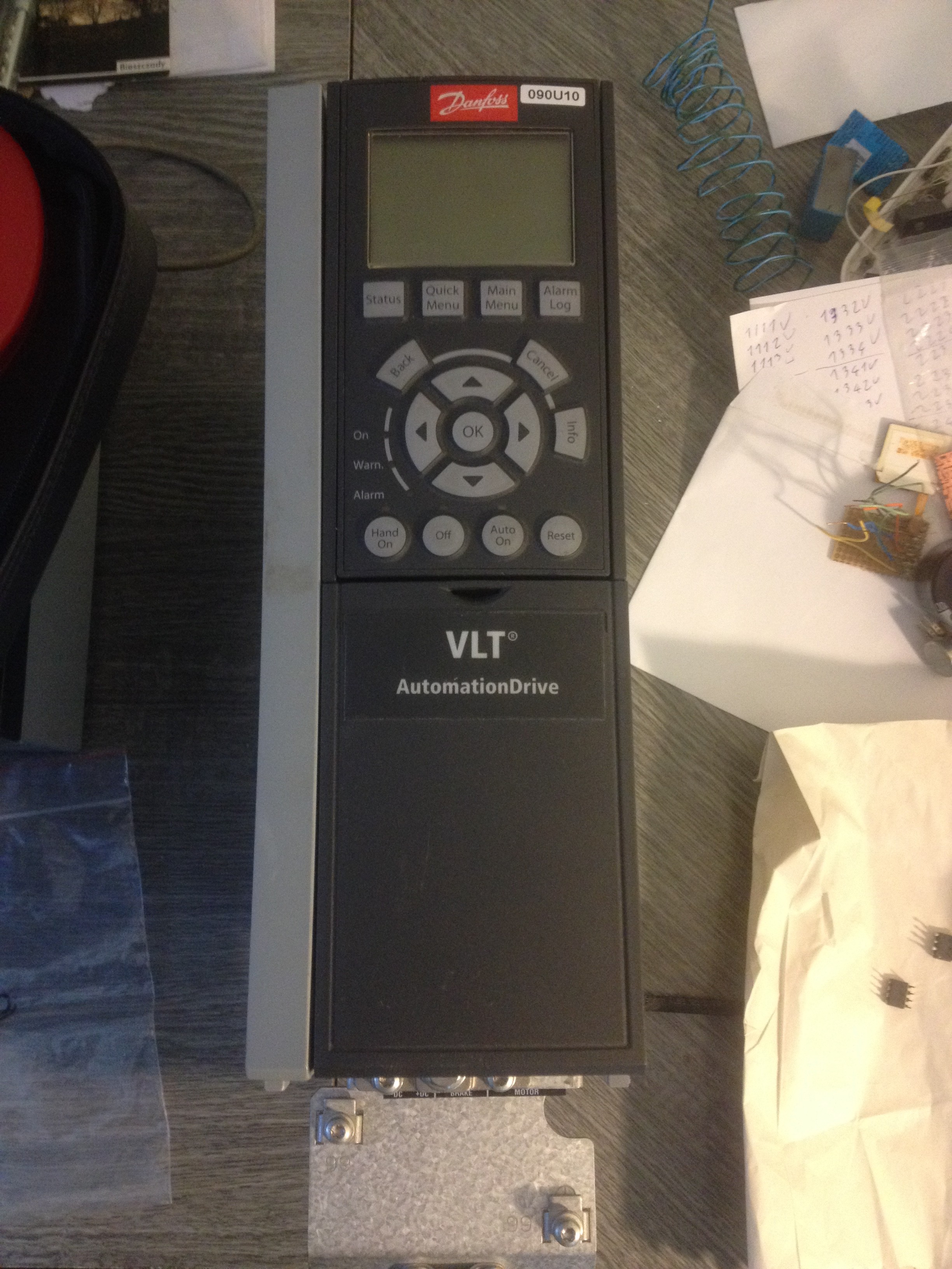
On this, I would like to show, how I repaired a Danfoss FC302 drive, which was faulty.

At the start it looked like this. This is a 2.2KW output power rated inverter, with 400V three phase input.

I knew it had a bad power section in it, but I would like to measure it. For the measurment you has to have a multimeter, with diode check function. At first I need the 3 phase input and the DC - bus lines for check, if the rectifier diodes are not shorted.

You can measure this, if you place one probe on the negative DC line first and then with the other probe you probe to the tree phase terminal. After the same with the positive DC line and the three phase terminal. If you did it right you shoud see the readings between 0,3V to 0,5V. If you see 0, you find a shorted diode, if nothing changed on the meter, you shoud reverse the probes or, that diode is also dead.

Often all diode good, but the IGBTs are bad, so now you have to check the IGBTs as well, before you can turn on the device.

The IGBTs have inside an antiparallel diode, so it helps with the measurments as well. Basically you can not check an IGBT inside the circuit, but what you can check is the antiparallel diode and it tells you a lot. Usually if the IGBT go bad, it go with the diode as well, so if you can not measure the diode, or you measure short, you get a bad IGBT as well.

You can measure the IGBTs with the same method then you measure the diode bridge on the input, so you put on a probe on the dc bus, with the other you check the output terminal on your drive.

Lets see an example how it is lookes like when your power modul get a short in it.

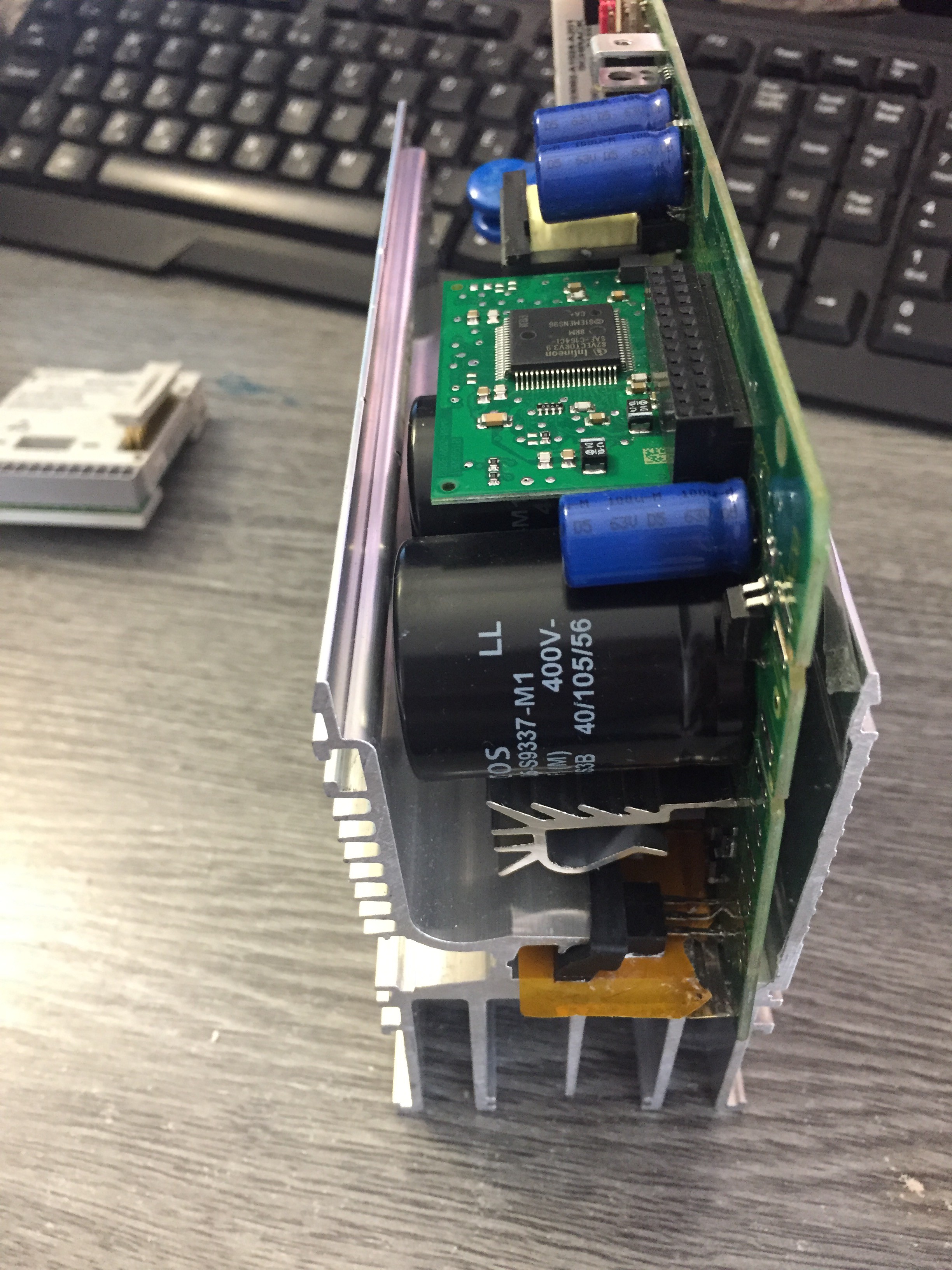
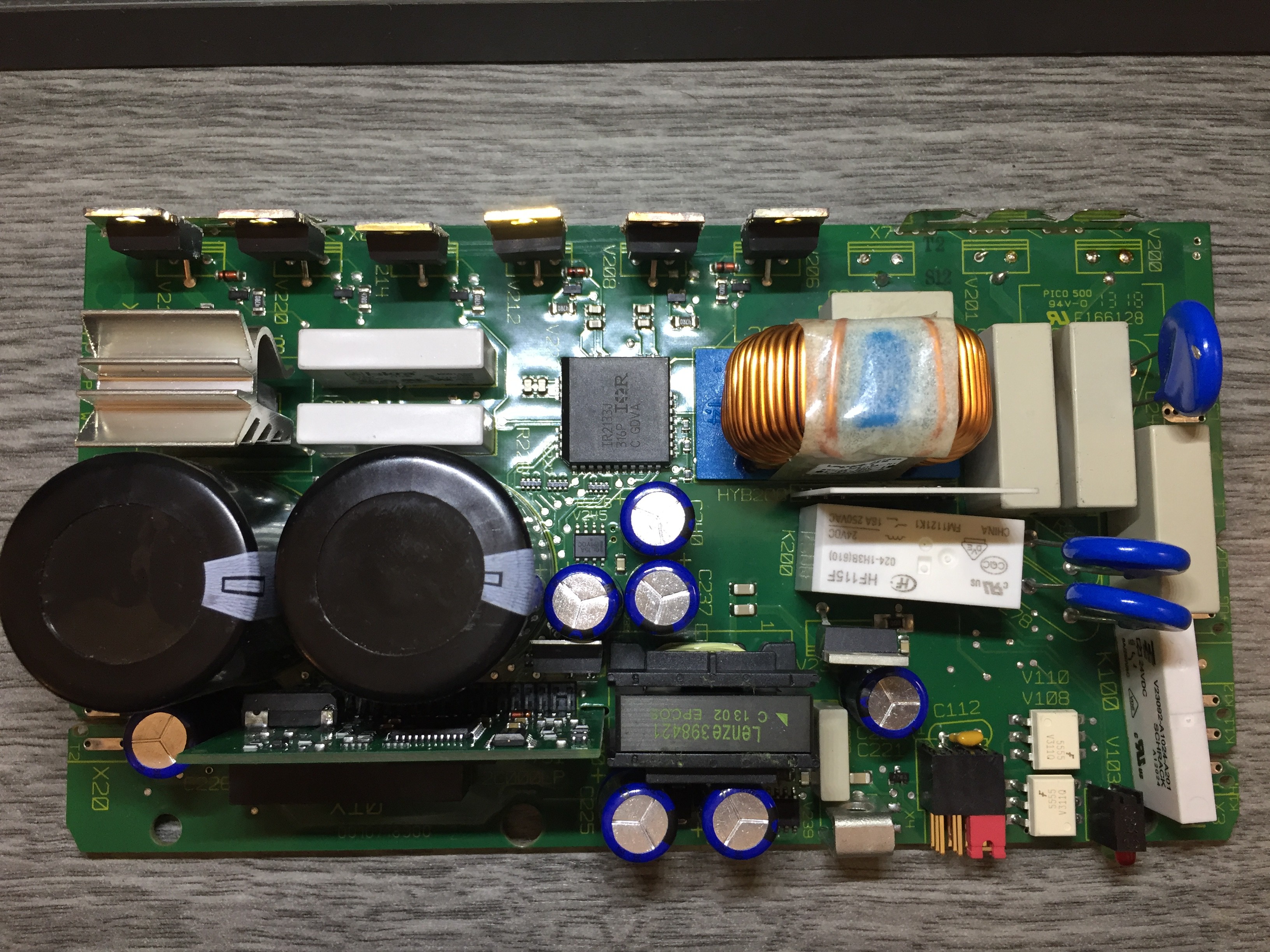
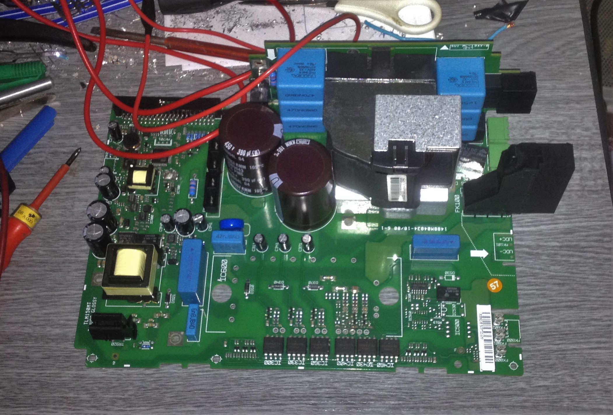
As I mentioned, sometimes you have to disassembly the entier device to measure the power section. It is the power section of the variable frequency drive that I repaired. Up there has the choke and the capacitators, on the left hase the switch mode power supply for the controller board and for the IGBT driver ICs.

The actual power modul already was soldered out from the pcb.

Here it is:
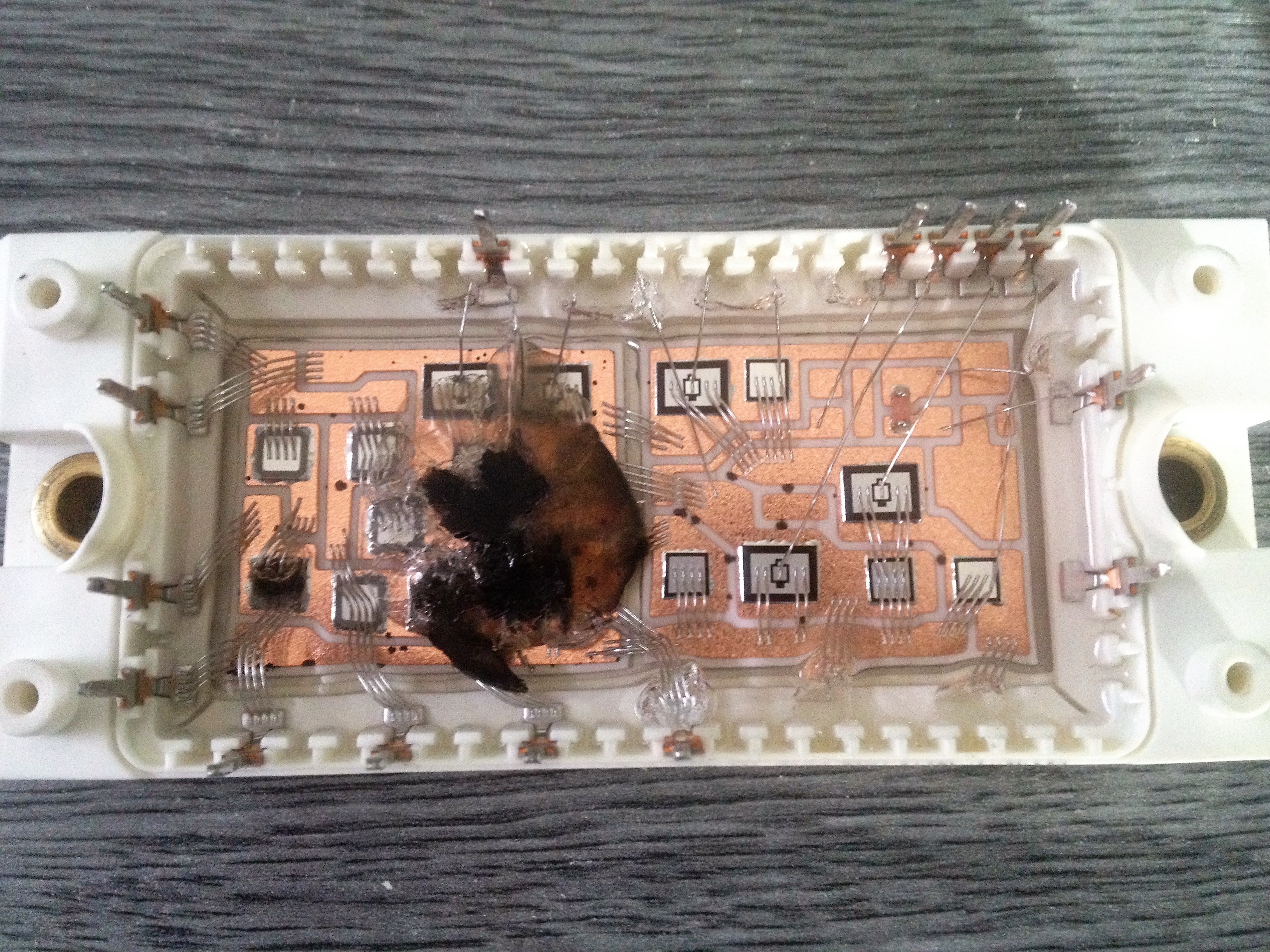
You can see it is an integrated power module, which has all the rectifier diodes and all the IGBTs in one package. This is a more effective way to save space in a drive, so it can be smaller.

These types of modules have some type of silicone that after the damage contains the smoke in it.

After I found the problem, I was seaching for an other power modul, which can substitute mine. I found one on the internet,...

Read more »
  • 1# Lenze 8200 vector drive

    Máté Tóth05/25/2017 at 21:30 2 comments

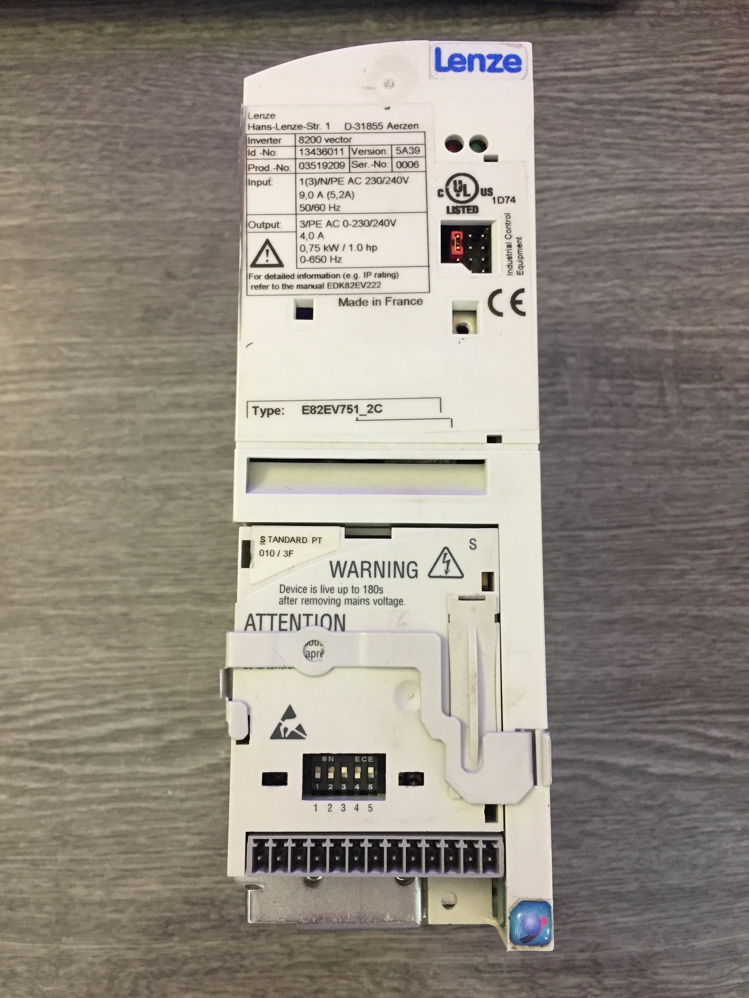
    I had some time, so I looked for a new drive. Later I find two lenze 8200 vector drive, one of them was actually good, but the other one, which one was a 0,75kW modell, it was bad.

    I bought both of them, and sell tested the good one, after them sell that for the price I bought the two drive, so I was at my money actually so I was not to worry about if I could not repair the other one.

    Lets start the repair storry of the bad drive:


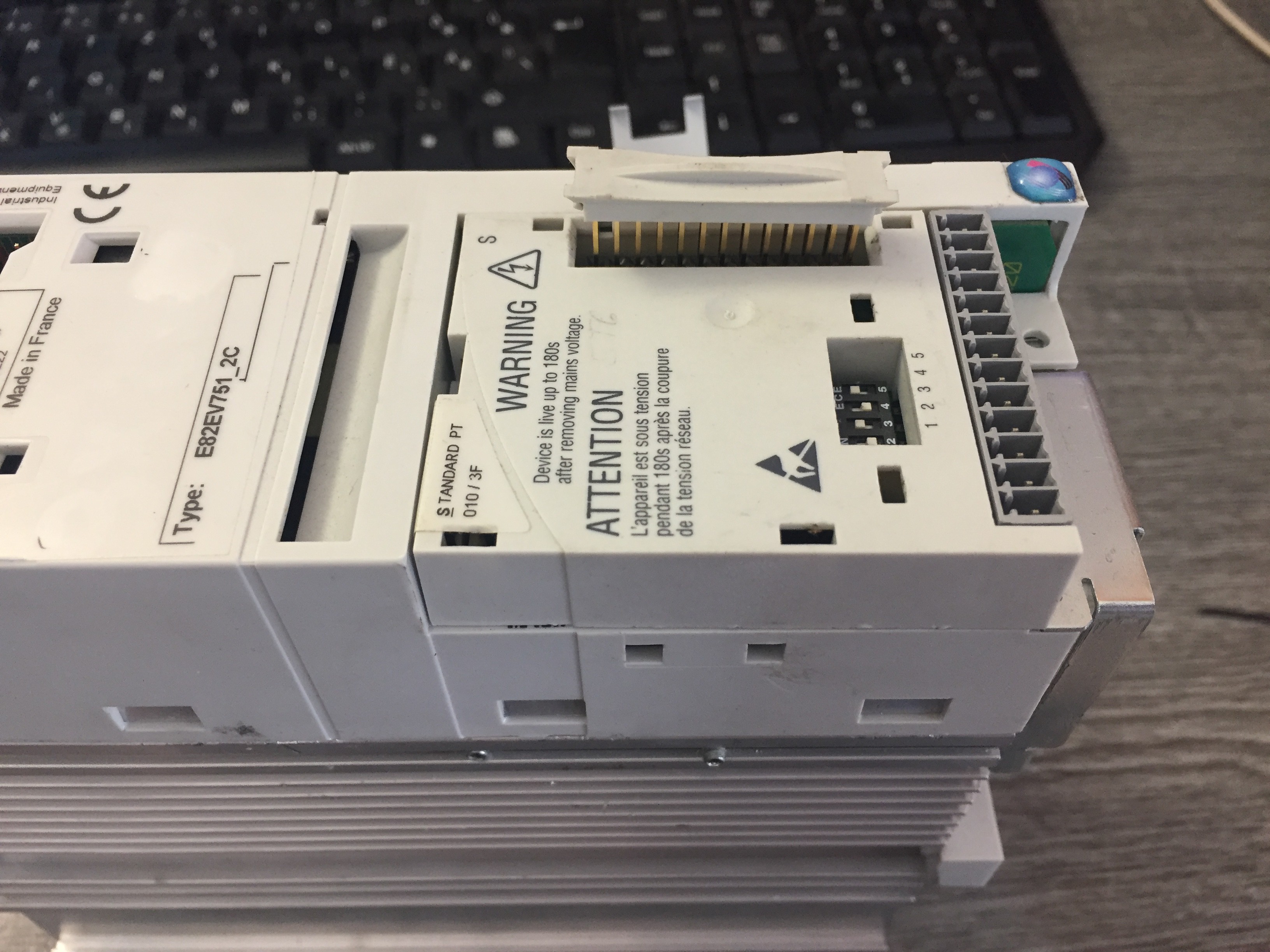
    I knew this drive was repaired before, because it was a repair company warranty sticker on it, but I was not to afraid of it, because I knew the company and they was not the best. The Lenze 8200 vector drives has a separated I/O modul, which I got with the unit, so I was lucky this time.

    As you can see it is a 3 phase 230V input modell, and it is capable of driving a 3 phase 0,75kW motors.

    For first time I looked if it hase any burn or smoke marks on the case, but this one was okay.

    It is important, you have to check the input rectifier diodes and the IGBTs before you can connect any power to it!

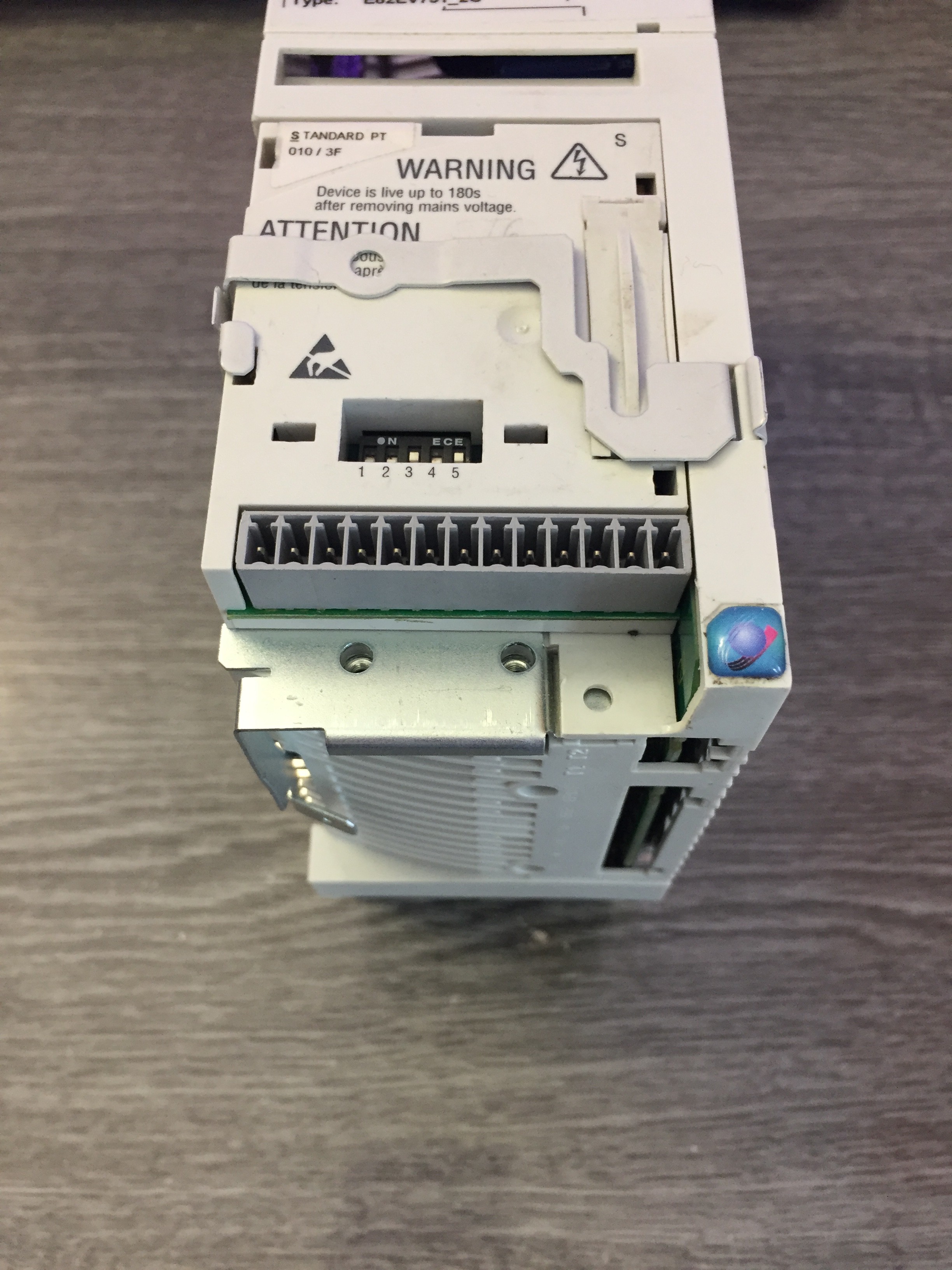
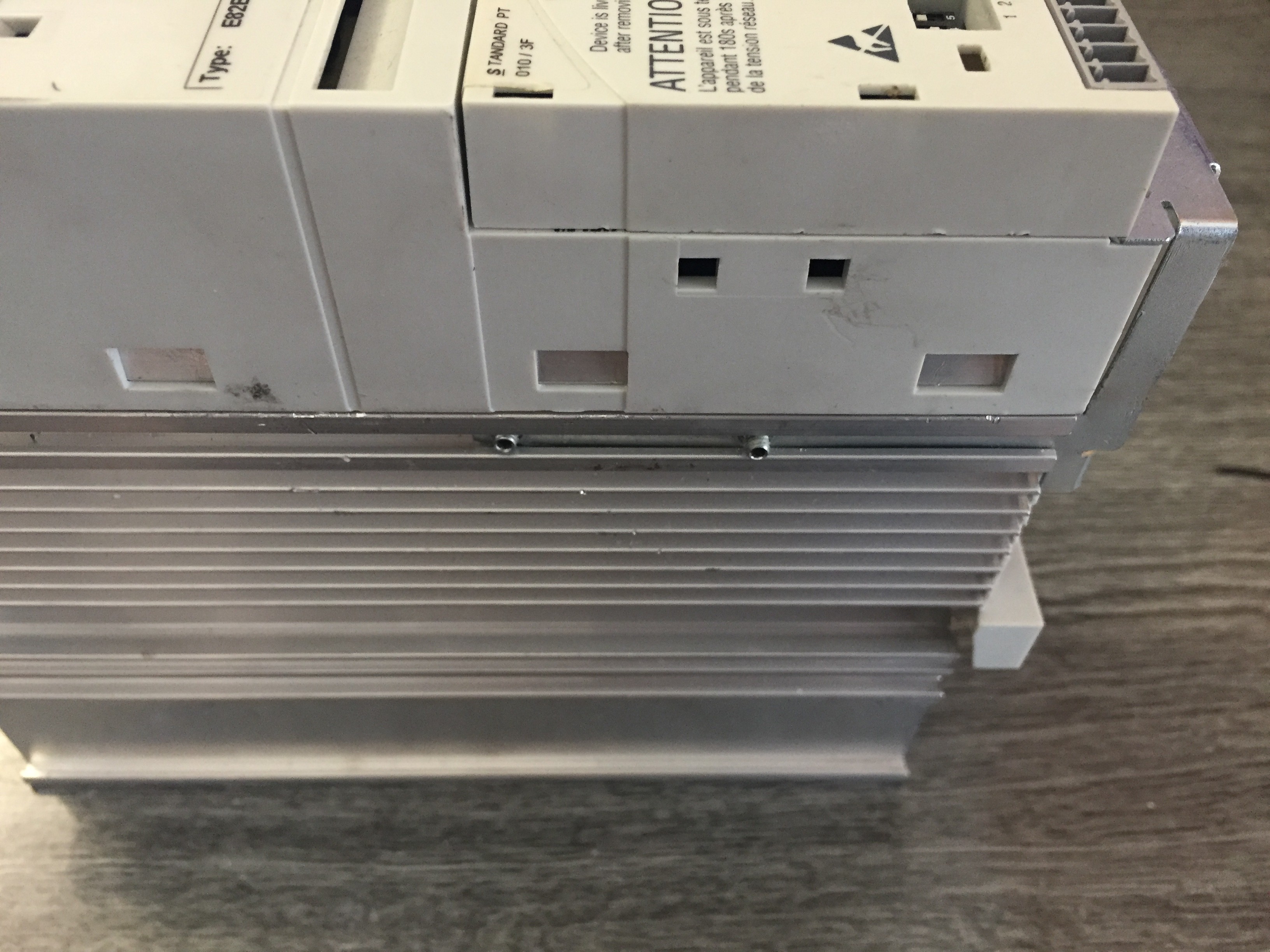
    This drive has all the main connections on the botton and the top.


    First you need a mutimeter with diode check mode and you have to find a way to measure the DC-BUS sometimes they make a connection for those like on this device marked like UG+/UG- . If you do not have those points you have to disassembly the device first.

    If you have those like I had, you can check the rectifier diodes if you put one multimeter probe on the DC-Bus (UG+/UG-) and the other you put on the input, marked with R-S-T or L1-L2-L3 you shoud get a  measurment like 0.5 or 0.6 V, if you have any continuous beep you have a shorted diode, so do not apply any power to the drive before you fixed it.

    You can chech the output the same way, but you measure the output marked with U-V-W and you shoud get as well 0.5-0.6V measurment on the multimeter. If you get 0V- you have a shorted IGBT, or if you have nothing you try to switch the probes if it is still nothing you have a bad IGBT as well.

    In my drive I measured both the inputs and the outputs, I got for shorted rectifier diode at the input, but no damage at the output side, so I was lucky, because I knew it would be a easy fix for me.

    Next step was, disassembly the case.

    On the smaller Lenze vector drives you first have to unscrew those two screw first, on the left side on the drive. After that you can pull backwards that metal.


    The second step is only if you have a I/O modul installed, you have to pull up the header with a flat screwdriver, after you can pop up the modul.


    The third step is pop the clips up on the case with a flat screwdriver.

    You shoud get the same result like I had.


    Now you can see it is not an easy assembly, because you have to bend the left side of the metal to get free those IGBTs and Diodes. If you bend it a little bit, you can push the circuit board out the metal heatsink/ case.

    You can see here I already disoldered the three diode and I left the six IGBT in place (left side top). 

    In the middle you can see a big IC, which is an integrated 3 phase IGBT driver. (IR2133J)

    At the middle bottom there is the transformer and next to it left the processor board vertically.

    Lets see those rectifier diodes:


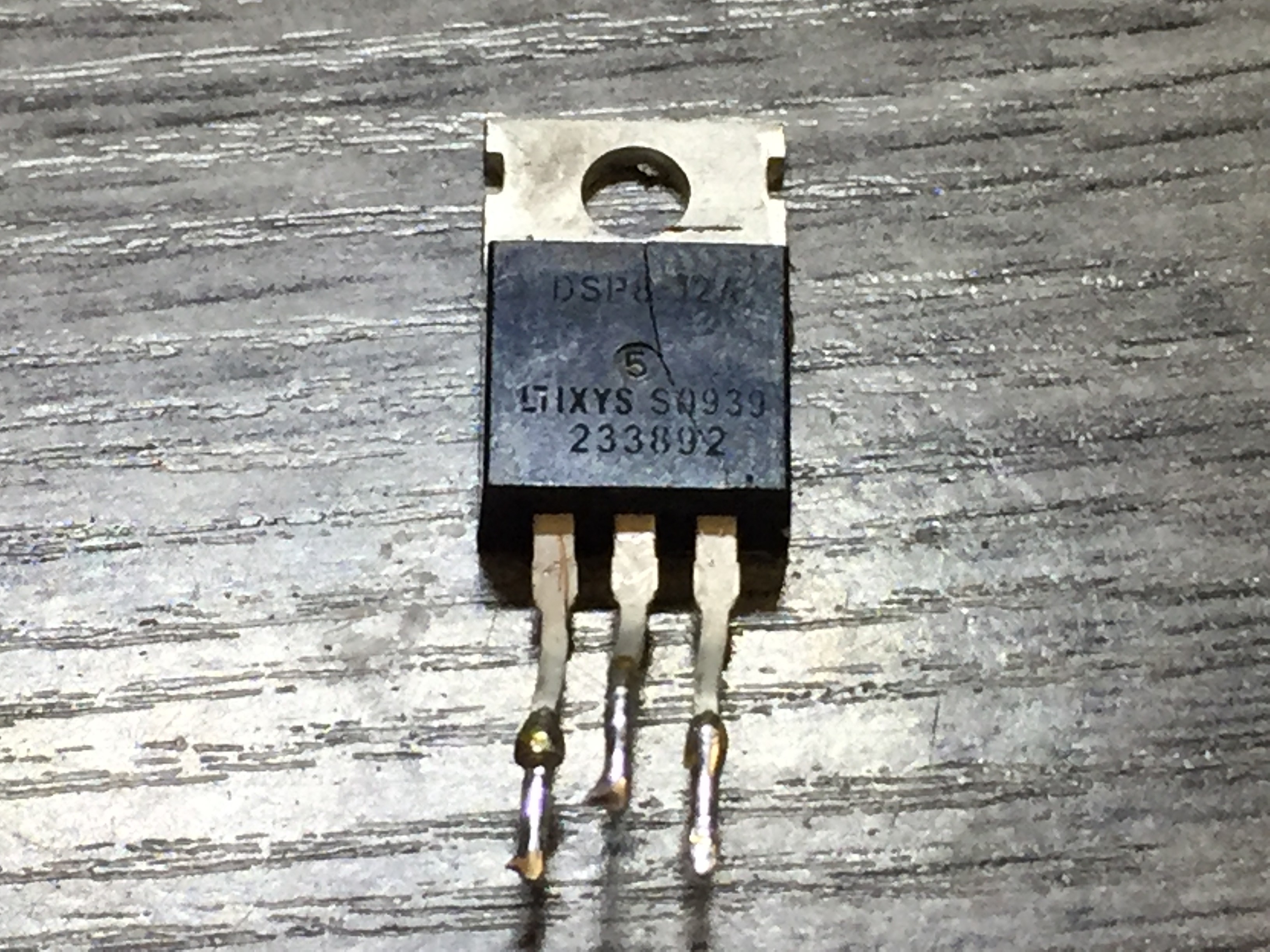
    One of the three locked like this, it cracked half, so it was obvious it is bad with an other on as well, which was not cracked, but that was short.

    I orderred three new one, because if one dies, useally an other get damage as well, so it is recomended to change all at the same time. 

    I changet it and assembled the drive and tested it with one phase. I put series with the drive an 100W light bulb, so if it changed there mind of the state of fixed, I shoud be safe, because the light bulb must limit the current so it would not blew up with that much energy.

    I had a success with the repair, I tested the drive and it worked perfectly.

View project log

Enjoy this project?

Share

Discussions

Ibrahim wrote 12/11/2023 at 08:55 point

hi. Thankyou for your shairing. I want to ask two questions.

1) my vfd gives constantly 540 V from break pins. Which section can I check?

2) My other VFD gives Over voltage fault. What do you think about its problem?

I will grateful if you response my questions.

  Are you sure? yes | no

Venkataramadasm wrote 09/17/2021 at 10:05 point

hi

i am looking for an book or on youtube about repairing the vdf and ac &dc drives.

thank you,

  Are you sure? yes | no

calennora wrote 08/20/2021 at 09:44 point

There are lots of solution available in the market but this guide is pretty unique thanks for sharing this project details here I am working on office removals project and needed this information for that.

  Are you sure? yes | no

espnmatv wrote 12/28/2019 at 19:55 point

I would like to add that the precharge circuits in a Powerflex 700 (Frame 4 and below) have either 1 relay or 3 relays in parallel depending on Frame size. The 3 in parallel act as one so if any of them short then the circuit will bypass the inrush resistors thus shorting them to zero Ohms. The precharge circuits with relays often go out on drives with many power cycles.  If any of these relays short then the precharge resistors are stuck in bypass. This issue WILL cause an inrush current that is not mitigated by the 41 Ohm precharge circuit and could charge the DC BUS Capacitors too fast causing dangerous catastrophic failure of a capacitor. Capacitors that sit for extended periods of time such as 2 years or longer need to be "reformed" before use in a drive or could potentially fail. The capacitors are configured in series if you have two. The capacitors are configured in series/parallel if you have four. Since they are 400VDC (480VAC 3 phase drives) this makes for 800VDC capacity and the Bus voltage (480 x 1.4) sits around 700Volts giving a hundred volt buffer for Deceleration spikes which generally only get to 750VDC.  If you have seen YouTube videos on capacitor failure then you may understand the seriousness of a failing capacitor. I would like to add that the capacitors blowing up on YouTube are not 400V nor are they thousands of Micro-farads so the magnitude is like comparing a BB to a Cannonball. Serious Injury or death can occur if safety measures are not taken into consideration when dealing with VFD operation or repair. Hopefully this post will inspire you to take extra precautions before performing repairs if you insist on being a hero. However I recommend you send your VFD to a reputable company such as ISAelectric for repair. The turnaround is very fast and it is safer to let a qualified person do the work that comes with a 2 year warranty. Always check that the BUS voltage is drained before touching any VFD, if the bleedoff resistors have an open circuit your BUS Voltage is there even without Line Voltage applied. Be Safe Please, Good Luck.

  Are you sure? yes | no

ubaldo.nava.0921 wrote 07/03/2019 at 16:01 point

hi! Let me congratulate you for your work it's awesome 

I would like to know if you can help me with something 

  Are you sure? yes | no

Máté Tóth wrote 10/22/2019 at 18:59 point

Hi! Sorry for the late reply, thanks for reading my post. What is the question?

  Are you sure? yes | no

m.hoseyn.karimi wrote 05/22/2019 at 11:38 point

hi

i am looking for an book or pdf about repairing the vdf  and ac & dc drives .

if anyone can help me , pls send me an email ?

  thank u so much

www.m.hoseyn.karimi@gmail.com

  Are you sure? yes | no

Similar Projects

Does this project spark your interest?

Become a member to follow this project and never miss any updates