 Turo Heikkinen
-
1ESP 8266 pin uses and restrictions
Not all ESP 8266's GPIOs are born equal, something I have now and then been banging my head at (and burned some ESPs). Some are hard wired for some use, like SPI clock and data, some wired to functionality like flashing and booting. For now Wemos D1 mini's pins, others to be added. Some limitations/features might be missing, to be added when bumped into.
Dev board Dx, Arduino IDE alias GPIO # Notes D0 16 - Wire to RST for timed wake from deep sleep
- Doesn't support interrupts, PWM, I²C, one-wireD1 5 Default I²C SCL, but others except D0 fine for that too. D2 4 Default I²C SDA, but others except D0 fine for that too. D3 0 - Needs to be pulled up for booting, down for flashing. Wemos has 10k pull-up, convenient for I²C.
- Used for booting/flashing, don't hard wire to GND/Vcc. Wemos has hard pull-down for flashing by serial RTS.
- Otherwise after boot works as a generic digital I/OD4 2 - Built in LED
- Wemos has 10k pull-up, convenient for I²C.
- Used for booting, doesn't boot up if pulled down while starting. ESP-12 doesn't seem to require a pull-up but recommended to have one.
- Otherwise after boot works as a generic digital I/OD5 14 Hardware SPI clock, but others can be used for software SPI. Fine for other uses. D6 12 Hardware SPI MISO, but others can be used for software SPI. Fine for other uses. D7 13 Hardware SPI MOSI, but others can be used for software SPI. Fine for other uses. D8 15 - Need to be pulled down for booting up, Wemos for example has 10k pull-down. Not good for I²C, which would require pull-up.
- Otherwise after boot works as a generic digital I/OA0 A0 ADC input, 0-1 V for generic ESP8266, 0-3.3 V for Wemos D1 mini (which has a 220k/100k resistor voltage divider) TX 1 Serial TX, other GPIO use possible RX 3 Serial RX, I²S DMA output, other GPIO use possible - 10 In ESP-12 modules and boards using them GPIO10 is connected to the internal flash, but in a pinch might be usable for own applications, if quad SPI modes not used. GPIO9 usually doesn't work but might, if you know what you're doing.
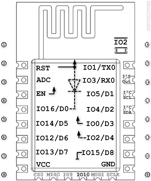
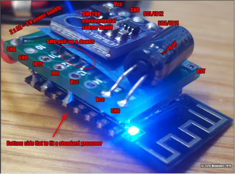
When running on batteries, I use ESP-12E/F (12S would be convenient as it has the required pull-up/downs internally, but I've had bad experience waking them from deep sleep due to too high resistance behind RST). This template I print on paper (six fit nicely on an A4) for planning/marking connections:![]()
Explanation:
- RST & EN pulled up (by a ~2.2-12k resistor)
- For wake-up from deep sleep, add a diode from RST to IO16 - this allows pulling RST low without interfering IO16
- Pull IO0 up (by a resistor)
- Recommended to pull IO2 up (by a resistor)
- Pull IO15 down (by a resistor)
- The LED is controlled by IO2, inverted
- IO3 / RX0 is also the I²S out pin, used for WS281x addressable LEDs etc
- IO4 & 5 are the default I²C SDA & SCL pins, others can be used as well but the defaults often allow running example code etc without modifications.
- The round pins 1-8 & 9-16 beside the ESP-12 image represent 1/10" / 2.54mm headers, can be used to plan wiring to a SOT-16 adapter, as below, or whatever PCB.
![]()
-
2Serial communication
After soon 60 years the RS-232 standard is doing strong, as that's what we're talking with to our most modern IoT thingys (yep I know about TTL vs positive/negative levels, pretty close anyway I'd say). Pretty much any MCU board talks RS-232 to the computer, nowadays generally through a UART inside the MCU board or cable, thus the Serial library is probably the most common denominator that's always available for I/O.
Initialization
None needed
Setup()
  Serial.begin(115200); //9600 would be more common, albeit slow, 74880 would print boot loader info as clear text instead of garbage
  while (!Serial) {} //Wait for OK
Use
//Output
    Serial.println("hello"); //With line feed
    Serial.println((String)"Temperature: " + temp + " humidity: " + humidity); //See Note
    Serial.printf("Temperature: %f humidity: %f\n", temp, humidity);
//Input
    if (Serial.available() > 0)
      if (Serial.peek() > 42) { //Ignore LF,CR etc
        int userInput1 = Serial.parseInt(); //Adjust number of these as needed. See Note2
        int userInput2 = Serial.parseInt();
      } else {
        Serial.readString(); //Ditch useless data
      }
Note1: The String concatenation method is something you should never do. Unless if lazy. just prototyping and have excess memory. Not that unlikely, if you are reading this.
Note2: parseInt is a dirty way to do input, quick for testing some parameters but for production you will write a proper input function.
-
3Network connectivity - TCP/IP and HTTP
For pretty much any ESP project I'd want the data to be sent to somewhere, thus networking would be like garlic in cooking - first chop it and then start wondering what are you actually going to cook.
Initialization
#include <ESP8266WiFi.h>
#include <ESP8266HTTPClient.h>
const char *WLAN_SSID = "My-network-SID-address";
const char *WLAN_PASSWORD = "My-network-pw";
HTTPClient http;
Setup()
WiFi.mode(WIFI_STA);
WiFi.begin(WLAN_SSID, WLAN_PASSWORD);
while (WiFi.status() != WL_CONNECTED) {
    delay(200);
    Serial.print(".");
}
Serial.println((String)"\nConnected: " + WiFi.localIP() + " RSSI: " + WiFi.RSSI());
Use (HTTP GET call)
// Helper function int doHttpGet(char *url) { int httpCode = -1; for(int i = 0; i < 20; i++) { http.begin(url); int httpCode = http.GET(); http.end(); Serial.print("URL: "); Serial.println(url); Serial.print("HTTP return code: "); Serial.print(httpCode); Serial.print(" "); Serial.println( http.errorToString(httpCode)); if(httpCode > 0) //Other retry codes can be added break; delay(5000); } return httpCode; } // Do the request: doHttpGet("http://my.url?val1=42&val2=4");3"); -
4Thingspeak
Values from all the sensors need to be sent somewhere to be visualized and processed. Thingspeak is a great free-for-hobbyists platform for that, you can store up to 3M measurements for one year, do all the possible processing with Matlab and easily visualize the stuff. Plus, you can any time easily export your data, should they change their hobbyist pricing policy or for long time storing.
THE SNIPPETS UNDER CONSTRUCTION, THE sendHttpThingspeak() FUNCTION DOES NOT WORK AS IS. Trying to figure out a general, elegant and compact way to send n values. I'd rather get rid of String, but Arduino's missing sprintf ("%f") is PITA.
These snippets require the networking ones from the previous section.Initialization
#define THINGSPEAK_URL "http://api.thingspeak.com/update?api_key=";
#define THINGSPEAK_KEY "YOURCHANNELKEYHERE"
Setup()
Nothing for Thingspeak - networking obviously needed, see previous section.
Use
// Helper function int sendHttpThingspeak(float v1=0,float v2=0,float v3=0,float v4=0,float v5=0,float v6=0,float v7=0,float v8=0) { String url = (String)THINGSPEAK_URL+THINGSPEAK_KEY+"&field1="+v1+"&field2="+v2+ "&field3="+v3+"&field4="+v4+"&field5="+v5+"&field6="+v6+"&field7="+v7+"&field8="+v8; return doHttpGet(url); } // To send the data (max 8 values): sendHttpThingspeak(temp1,humi1,pressure,humidity,WiFi.RSSI()); -
5Writing float to character buffer (obsolete, as ESP with Arduino IDE nowadays supports floats fine with sprintf)
When you'd normally do sprintf(myBuffer, "%f",myFloat ), you won't when coding with the Arduino suite, as the embedded sprintf library doesn't do floats.
Serial.print etc do support floats, but if you really insist on formatting the number in a character buffer, you might do something like this:
#include  //Required by dtostrf
pi = 3.141592654;
char tempBuf[32];
char outBuf[64];
int decimalPlaces = 3;
sprintf(outBuf, "Pi ~ %s\n",dtostrf(pi, decimalPlaces+2, decimalPlaces, tempBuf)); //ouBuf contains "Pi ~ 3.142"
And how exactly do dtostrf parameters work?
dtostrf(13.141593, 5,3, buf) -> [13.142]
dtostrf(3.141592, 5, 3, buf) -> [3.142]
dtostrf(13.141593, 0, 3, buf) -> [13.142]
dtostrf(314.592654, 8, 2, buf) -> [ 314.59]
Also the String class of C++ is available in the Arduino framework, often seen evil in the embedded world, as these C++ classes don't tend to be that resource friendly. So, let's try some options; manual, dtostr and String:
- printf("Pi ~ %d.%d\n",(int)pi,(int)((pi - (int)pi) * 1000 ));
- 2x above for 2 float inserts
- 2x printf("Pi ~ %d.%d, pi2: %d.%d, pi4: %d.%d\n",(int)pi,(int)((pi - (int)pi) * 1000 ),(int)(pi+2),(int)(((pi+2) - (int)(pi+2)) * 1000 ),(int)(pi+4),(int)(((pi+4) - (int)(pi+4)) * 1000 ));
vs
- printf( "Pi ~ %s\n",dtostrf(pi, decimalPlaces+2, decimalPlaces, tempBuf) );
- 2x above
- 2x printf( "Pi ~ %s, pi2: %s, pi4: %s\n",dtostrf(pi, decimalPlaces+2, decimalPlaces, tempBuf),dtostrf(pi+2, decimalPlaces+2, decimalPlaces, tempBuf),dtostrf(pi+4, decimalPlaces+2, decimalPlaces, tempBuf) );
vs
- printf( ((String)"Pi ~ " + pi + "\n").c_str() );
- 2x above
- 2x printf( ((String)"Pi ~ " + pi + ", pi2: " + (pi+2) + ", pi4: " + (pi+4) +"\n").c_str() );
Flash / RAM use results as tables:
Flash 1 float insert 2 6 Manual 222047
+0222063
+0222103
+0dtostr 223935
+1888223967
+1904224095
+1992String 224585
+2538224665
+2602224777
+2674As expected, the manual way is the clear winner and String the last, not too much after dtostr. With ESPs having megabytes of flash, I'll generally be happy to sacrifice ~2.5K for a great amount of readability, maintainability and reduced bugs. Professionally I'm not using C++ Strings with MCUs, but for my home hacks I don't see any problem.
Good to see that the compiler scales all the options really well, for example generating two Strings with three floats each increased size just 136 bytes, about 5% of the original overhead of String.
RAM 1 2 6 Manual 31580
+031580
+031612
+0dtostr 31616
+3631616
+3631632
+20String 31596
+1631596
+1631612
+0Not that much difference here, String with two strings and 6 float inserts actually took exactly as much RAM as the manual way.
-
6GPIO & timer interrupts, sleep
For anything battery powered you don't want the CPU be looping your code full speed while just waiting for some action. For this there are interrupts, for example timer and GPIO state change ones.
GPIO state change
#define GPIO_INTERRUPT D5 //Anything but D0/GPIO16 OK
bool actionRequest = false; //Flag for action
//Function to be executed when interrupt occurs
void interruptAction() {
  actionRequest = true; //We cannot use much time here
}
setup() {
  pinMode(GPIO_INTERRUPT, INPUT_PULLUP);
  attachInterrupt(digitalPinToInterrupt(D5), interruptAction, FALLING); //Or RISING | CHANGE
}
loop() {
  if(actionRequest) {
    doAction();
    actionRequest = false;
  }
}
Timers
#define TIMER_INTERVAL_MS 30 * 1000
extern "C" {
  #include "user_interface.h" //For os_timer_t etc
}
os_timer_t myTimer;
bool actionRequest = false;

void timerActionFunction(void *pArg) {
  actionRequest = true; //Again have to be quick
}
setup() {
  os_timer_setfn(&myTimer, timerActionFunction, NULL); // Set timer callback
  os_timer_arm(&myTimer, TIMER_INTERVAL_MS, true); // Set timer time
}
loop() {
  if(actionRequest)
    doTimerRequestAction();
}
Deep sleep
For battery use you'll want deep sleep, with 10-20uA current draw. To get there need also to pop off the LED and UARTs, thus Wemos D1 Mini might not be the primary choice.
Code for deep sleep is rather trivial, but to actually wake the ESP you need to wire D0/GPIO16 to RST. Pulling RST low by an external sensor/switch/reed switch also wakes it up. Waking up means booting from scratch, so need to reconnect to WiFi (which is BTW much quicker -like 200 ms vs 4 s- with fixed IP vs DHCP, quite a difference when on tight energy budget), if connection required. Also RAM is lost, so things to remember need to be written to EEPROM (to be documented) or somewhere in the clouds.
#define SLEEP_SECONDS 5 * 60 //Max 4294 seconds = 71 min 34 sec
ESP.deepSleep(SLEEP_SECONDS * 1e6); //microseconds, max 2^32-1
// Execution never gets here
The ESP library: https://github.com/esp8266/Arduino/tree/master/cores/esp8266
-
7Persistent variable storage - EEPROM, RTC, SPIFFS
With the ESP it is common to use the deep sleep mode to conserve power, but when waking from deep sleep it starts from the beginning, contents of every variable forgotten. Often this is OK, but if you want to store a state, configuration value or a previous measurement value for future reference, you'll have several options.
With all the options, remember that a reset occurring while writing (not as unlikely as it may sound; writing requires some power, thus lowering voltage, which may cause a reset) will likely corrupt your data being written, use CRC and/or backup data to confirm your data is OK.
EEPROM
Probably the easiest way is to use the "EEPROM", which in an ESP actually is a sector in the flash memory. Rather easy to use, but has a limited number of writes. The flash chip used in ESP8266-12E/F, which the Wemos also contains, is specsed to 100k writes, which would be OK for 27 writes per day over 10 years, not good for writing every five seconds. For writing seldom changed configuration data, like SSID & password for WiFi networks, that would be plenty, for measurements you decide. Up to 4096 bytes can be saved there.
#include

void setup() {
  EEPROM.begin(512); // Size to reserve, 4 to 4096 bytes
}
void storeByteToEeprom(int start, uint8_t val) { //Address in EEPROM, value
  EEPROM.write(start, val);
  EEPROM.commit(); //Needed to execute the write
}
uint8_t readByteFromEeprom(int start) {
  return EEPROM.read(start);
}
void storeStringToEeprom(int start, const char* str) {
  for (int i = 0; i <= strlen(str); i++) {
    EEPROM.write(start + i, (uint8_t) str[i]);
  }
  EEPROM.commit();
}
char * readStringFromEeprom(int start, char * charBuf, int bufLen) {
  for (int i = 0; i <= bufLen; i++) {
    charBuf[i] = (char)EEPROM.read(start + i);
  }
  return charBuf;
}
(Parameter checking to be added, the exact code to be tested..)
Internal RTC memory
The "RTC" of an ESP might be slightly misleading, as it only keeps time from the first power on, but for this purpose we're fine. Inside the ESP there are 128 32-bit slots = 512 persistent bytes available for reading and writing. Doesn't seem to be clear what kind of memory it is, likely survives more write cycles than the flash "EEPROM".
uint8_t slot = 0; //0 to 127,4 bytes each
uint32_t dataBuffer[64]; //Max 512 needed
uint32_t numberOfBytesToStore = 64; //4 byte chunks, 4-512 bytes
if( !ESP.rtcUserMemoryWrite(slot, dataBuffer, numberOfBytesToStore) )
  Serial.println("Storing data to RTC failed");
if( !ESP.rtcUserMemoryRead(slot, dataBuffer, numberOfBytesToStore) )
  Serial.println("Reading data from RTC failed");
Easy interface to the RTC memory with checksum validation:
The RTC memory is written as 32 bit slots - these two functions use the low 16 bits as the value itself and the high ones as the checksum (XOR of the value). This way we can be pretty sure a value read is something we have written earlier ourself, very important and not trivial after a fresh boot. Sure it does waste half of the memory for simplicity; if you need more than 16 bits times 128 slots you'd want to write your own functions having common checksums for larger blocks, or whatever suits your needs.
// Write 16 bit int to RTC memory with checksum, return true if verified OK
// Slot 0-127
// (C) Turo Heikkinen 2019
bool writeRtcMem(uint16_t *inVal, uint8_t slot = 0) {
  uint32_t valToStore = *inVal | ((*inVal ^ 0xffff) << 16); //Add checksum
  uint32_t valFromMemory;
  if (ESP.rtcUserMemoryWrite(slot, &valToStore, sizeof(valToStore)) &&
      ESP.rtcUserMemoryRead(slot, &valFromMemory, sizeof(valFromMemory)) &&
      valToStore == valFromMemory) {
        return true;
  }
  return false;
}

// Read 16 bit int from RTC memory, return true if checksum OK
// Only overwrite variable, if checksum OK
// Slot 0-127
// (C) Turo Heikkinen 2019
bool readRtcMem(uint16_t *inVal, uint8_t slot = 0) {
  uint32_t valFromMemory;
  if (ESP.rtcUserMemoryRead(slot, &valFromMemory, sizeof(valFromMemory)) &&
      ((valFromMemory >> 16) ^ (valFromMemory & 0xffff)) == 0xffff) {
        *inVal = valFromMemory;
        return true;
  }
  return false;
}
A very simple example using the above:
uint16_t counter = -1;
readRtcMem(&counter);
counter++;
writeRtcMem(&counter);
If the slot zero hadn't been initialized by a number+checksum earlier, readRtcMem() would fail and leave counter as is = -1 = 0xffff, which would then be increased to zero and written to the RTC memory. The next time the RTC slot zero would contain 0xffff0000, be validated OK and returned as zero, increased by one, written back and so on.
A more detailed deep sleep counter example using the above functions:
void setup() {
  Serial.begin(115200);
  uint16_t counter;
  if(readRtcMem(&counter)) {
    counter++;
  } else {
    counter = 0;
  }
  Serial.printf("Counter: %u\n",counter);
  if(!writeRtcMem(&counter)) {
    Serial.printf("RTC write failed\n");
  }
  ESP.deepSleep(5 * 1000000);
}
Data read/written in 4 byte chunks. Check your slot & buffer length values, ESP.rtcUserMemory* have bugs there.
- Esp.cpp defining the functions used above
External RTC memory
External I²C or SPI Real Time Clock chips like the DS1307 or modules based on that or DS3231 (which doesn't have memory of its own) have/may have NVRAM or more durable EEPROM than the ESP.
- NVRAM doesn't have any write cycle limitations but require battery back-up and are small like 56 bytes of user memory.
- EEPROMs have kilobytes (typically 4 or 8) of storage but limited write cycle count (1M for Atmel 24C32, ten times that of an ESP module).
Using NVRAM of a DS1307:
#include
#include
RtcDS1307<TwoWire> Rtc(Wire);
void setup() {
  Wire.begin(3, 4); //To define I2C pins
  Rtc.Begin();
}
void loop() {
  //Storing and retrieving a byte
  Rtc.SetMemory(0, 42); //Store byte "42" in address 0. Address can be 0 to 55.
  uint8_t recoveredValue =  Rtc.GetMemory(0); //Get it back
  //Storing a string and its lenght
  const char dataBuffer[] = "Data to be stored";
  uint8_t lenWritten = Rtc.SetMemory(2, dataBuffer, sizeof(dataBuffer) - 1); //Store string (minus terminator) starting from address 2
  Rtc.SetMemory(1, lenWritten); //Store string length to address 1
  //Retieving the string
  uint8_t lenToRead = Rtc.GetMemory(1);
  uint8_t readBuffer[20];
  uint8_t lenActuallyRead = Rtc.GetMemory(2, readBuffer, lenToRead);
  if( lenToRead != lenActuallyRead )
    Serial.println("Couldn't read all data from external RTC);
}
(Need to get a DS1307 to test the code. Have used NTP for real time clock so far.)
- External RTC Library
- DS1307 datasheet (with 56 bytes non-volatile RAM, unlimited writes)
- DS3231 datasheet (no persistent memory of its own)
- Atmel 24C32 EEPROM datasheet (used in many RTC modules, 1M write cycles)
SPIFFS
SPI Flash Filing System (SPIFFS) is a simple flat file system supported by the ESP. Files like images, static web pages or templates can be stored in the flash memory using SPIFFS, it has wear balancing to make it live beyond the 100k writes.
Haven't used it so far, code to be added when getting to know it better.
Plenty of information available to start from.
-
874HC4051 Multiplexer
When I needed to get data from three analog sensors (MQ-131, MQ-135 and TG-2602 gas/air quality sensors) to be sent somewhere to be stored and graphed, I thought of the then brand new ESP32, and its freely configurable analog input mapping. Too bad I couldn't find an ESP32 dev board that would support an external antenna, and the internal antennas of the ones I got didn't reach far enough. Back to ESP8266, with a single ADC (Analog to Digital Converter) input. No problem, let's get an analog multiplexer like the 74HC4051, which supports eight analog lines multiplexed to one, selected by three pins. I didn't have such a nifty breakout board as the Sparkfun above, but soldered a SOP16 on a SOP-to-DIL adapter board. In the Sparkfun board you can see the pinx Y0-Y7, one of which is always connected to the pin Z, selected by the pins S0-S2.
When using a 74HC4051 directly without a breakout board like the one above, you need to wire Vee to either ground, if using only positive analog voltages, or minus whatever, if +/- voltages required (with the SparkFun board unsolder JP1 to use negative voltages).
The active-low E pin should be pulled down by a resistor ( 1-10k or something, doesn't really matter). At least the ones I got are active if left unconnected, but might not be reliable.
Initialization
//Pull down S1, S2, if not wired to MCU
#define PIN_MUX_S0 D5
#define PIN_MUX_S1 D2  //Leave out, if 2 pins enough
#define PIN_MUX_S2 D1  //Leave out, if 4 pins enough
#define MUX_MYANALOGSENSOR1 0  // Y0
#define MUX_MYANALOGSENSOR2 1  // Y1
#define MUX_MYANALOGSENSOR3 2  // Y2
Setup()
  pinMode(PIN_MUX_0, OUTPUT); digitalWrite(PIN_MUX_S0, LOW);
  pinMode(PIN_MUX_1, OUTPUT); digitalWrite(PIN_MUX_S1, LOW);  //Leave out, if 2 pins enough
  pinMode(PIN_MUX_2, OUTPUT); digitalWrite(PIN_MUX_S2, LOW);  //Leave out, if 4 pins enough
Use
//Helper function float analogReadMux(uint8_t analogPin, uint8_t muxSelected) { digitalWrite(PIN_MUX_0, bitRead(muxSelected,0)); digitalWrite(PIN_MUX_1, bitRead(muxSelected,1)); //Leave out, if 2 pins enough digitalWrite(PIN_MUX_2, bitRead(muxSelected,2)); //Leave out, if 4 pins enough return analogRead(PIN_ADC); } //The actual read commands: int sensor1value = AnalogReadMux(PIN_ADC, MUX_MYANALOGSENSOR1); int sensor2value = AnalogReadMux(PIN_ADC, MUX_MYANALOGSENSOR2) -
9MCP4725 I²C DAC
Digital to analog converters (DACs) are best known for playing music or video, but are useful for many use cases of controlling the analog world from the digital domain. For example, switching power converters' output voltage can be controlled by a DAC , thus allowing motor (like computer fans)) or light control using a MCU. With such DAC based control, ESP's sleep mode can be used, as the low power DAC holds the voltage while the MCU can sleep, unlike PWM which needs the MCU running all the time.
Library: https://github.com/adafruit/Adafruit_MCP4725
Datasheet: http://ww1.microchip.com/downloads/en/DeviceDoc/22039d.pdf
Initialization
#include  // I2C
#include
#define DAC_OPERATING_VOLTAGE 3.3 // For dac_voltage2value. MCP4725 Vcc 2.7-5.5 V, output voltage 0-Vcc.
Adafruit_MCP4725 dac; // Add lines for dac2 etc for multiple MCP4725 devices
Setup()
  Wire.begin(D3,D4); //Line not required for (D2,D1)
  dac.begin(0x62); //Other addresses possible. Multiple devices need to be configured to different addresses.
Use
//Helper function uint32_t dac_voltage2value(float voltage) { int32_t value = voltage / DAC_OPERATING_VOLTAGE * 4095; value = value < 0 ? 0 : (value > 4095 ? 4095 : value); return value; } To set the DAC voltage: dac.setVoltage(dac_voltage2value(2.0)); // 2 volts. -
10Analog to Digital Converter (ADC)
![]()
Embedded computing is basically computing integrated to the real world, and the real world is pretty much analog. By default, electrically measuring analog real world values produces analog voltage or current (which can be converted to voltage using a resistor) ranges. Sure there are many sensors with digital interfaces, but often analog sensors are cheaper and/or more available than digital ones. Also user-etc-mechanical input with variable resistors or resistor ladder setups produces analog voltages. All in all, measuring (and generating as well, check "DAC") analog voltages is an important task in the embedded world.
Measuring voltage is done by an Analog to Digital Converter, ADC, which can be anything between a few resistors to devices costing thousands of dollars. The ESP8266 has one 10-bit ADC, measuring values between 0 and 1 volts. Some modules such as the Wemos D1 Mini have an integrated resistor ladder for supporting broader voltage ranges like D1's 0 - 3.2 volts. ESP32 has two 12-bit ADCs, that can be mapped to 18 of the GPIOs. Using ESP32's ADC is quite a topic of its own, I'll write about that later.
Reading analog values:
uint16_t analogValue = 0;
analogValue = analogRead(A0); // Returns integer value 0-1023
Converting to voltage:
#define ADC_MULTIPLIER 3.2 //1 for plain 8266, 3.2 for Wemos D1 Mini etc

uint16_t Adc2Voltage(uint32_t raw) { //32 bits so that we can freely multiply later
  long res = raw * 1000 * ADC_MULTIPLIER / 1024; //mV
  return res;
}

uint16_t voltageMv = Adc2Voltage(analogRead(A0));
Cooking it further to return a given range:
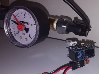
#define ADC_MULTIPLIER 3.2 //1 for plain 8266, 3.2 for Wemos ETC
#define ADC_VOLTAGE_MIN_MV 500 //Input mapping minimum
#define ADC_VOLTAGE_MAX_MV 4500 //Input mapping maximum
#define ADC_OUT_MIN 0 //Output mapping minimum
#define ADC_OUT_MAX 12000 //Output mapping maximum

uint16_t AdcConvRaw(double raw) {
  double res = raw * 1000 * ADC_MULTIPLIER / 1024; //mV
  res = (res - ADC_VOLTAGE_MIN_MV) * (ADC_OUT_MAX - ADC_OUT_MIN) / (ADC_VOLTAGE_MAX_MV - ADC_VOLTAGE_MIN_MV) + ADC_OUT_MIN;
  return 0.5 + res > ADC_OUT_MAX ? ADC_OUT_MAX : res < ADC_OUT_MIN ? ADC_OUT_MIN : res;
}

#define AVG_WINDOW 100

double analogSum = 0;
for(uint8_t i = 0; i < AVG_WINDOW; i++)
  analogSum += analogRead(A0);
analogSum /= AVG_WINDOW;
uint16_t analogPressure = AdcConvRaw(analogSum);
The above snippet reads and averages 100 samples and converts the float result to integer pressure value for a liquid pressure sensor. In this case we have a multiplier of 3.2 for a Wemos or so, which will measure 3.2 volts or more as the full ADC value 1023. This sensor has a linear voltage-pressure relation; 500 mV means 0 bars (difference to atmosphere) and 4500 mV means 12 bars (defined as millibars above).
Using floats clearly is not the most cycle friendly method, but this way I can easily use oversampling to increase resolution and in most real world data gathering devices I don't really care if the process takes micro- or milliseconds (unless optimized for battery).
ESP cookbook
Collecting snippets that can quickly be copied to assemble a program for different sensors etc. Mostly about ESP8266/32 with Arduino IDE.
Discussions
Become a Hackaday.io Member
Create an account to leave a comment. Already have an account? Log In.