 Turo Heikkinen
-
21Placeholder-2
Stuff to be added here.
-
220.96" / 1,3" I²C OLED displays
These require only two GPIOs (shared with other I²C devices) for full pixel control, and U8G libraries make them very easy to use. The 0.96" ones are small-ish for many applications, where the display might be further than your hand, but cheap enough (can be had at about $2.5 from eBay, AliExpress etc) to add into pretty much any project for some troubleshooting output. The big brother 1.3 inch one has almost twice the screen area, and is much more useful for wall thermometers etc, price about twice of the smaller one.
All my displays use either SH1106 or SSD1306, which are mostly compatible, but if some pixel columns show random data, try initilizer for SH1106.
Initialization
#include <U8g2lib.h>
#include <Wire.h>
#define PIN_OLED_SCL D3
#define PIN_OLED_SDA D4
//Check others from U8g2 documentation, if doesn't work
U8G2_SSD1306_128X64_NONAME_F_SW_I2C u8g2(U8G2_R0, PIN_OLED_SCL, PIN_OLED_SDA);
setup()u8g2.begin();Use
u8g2.setFont(u8g_font_unifont); u8g2.clearBuffer(); u8g2.drawStr( 0, 12 , "Hello"); u8g2.sendBuffer(); u8g2.setCursor(0,27); u8g2.print("world"); u8g2.sendBuffer(); -
230.96 / 1.3" SPI OLED displays
Accidentally got a bunch of these weird 6-pin SPI displays disguised as I²C (or multi-protocol) ones. The item title mentioned IIC and I2C four times, and the photo had the I²C pins SDA & SCL, so kinda thought they would be I²C displays, but SPI only they were. Fortunately AliExpress understood and I got full refund, without needing to return the displays.
BTW, these SH1106/SSD1306 based displays seem to have a rather standard layout 30-pin flex cable, whose pinout can be found for example here. That matched with the display controller's datasheet (SH1106 and SSD1306 are pretty much compatible, AFAICS just a couple of pixels coordinate shift due to 1306 having a narrower display buffer) tells that the trace number 11 (BS1 / IM1) should be changed from low to high to switch to I²C. My displays' IM1 traces are hard wired to ground somewhere out of sight so haven't bothered trying to convert them.
SCL and SDA do not belong in SPI, thus wiring is not obvious. Anyway, here's what worked with my displays:
Display ESP8266 GND GND VCC 3V3 SCL (clock) D5 (ESP's hardware serial clock SCK, in software SPI most GPIOs OK) SDA (data in) D7 (ESP's hardware MOSI line, in software SPI most GPIOs OK) RST (reset) D4 (most GPIOs should work) D/C (data / command) D0 (most GPIOs should work) (No chip select pin) U8X8_PIN_NONE can be used for non-existing CS Initialization
#include #include <Wire.h> #include <U8g2lib.h> #define OLED_ROTATION U8G2_R0 //Rotation 0-3 #define PIN_OLED_SCK D5 //Hardware SCK line, can be changed in software SPI - "SW" in the constructor #define PIN_OLED_MOSI D7 //Hardware MOSI line, can be changed in software SPI - "SW" in the constructor #define PIN_OLED_RESET D4 #define PIN_OLED_DC D0 #define PIN_OLED_CS U8X8_PIN_NONE // Screen buffer 1|2|F -v vv--- HW for hardware SPI: SCK and MOSI fixed to D5 & D7, not working with my displays U8G2_SH1106_128X64_NONAME_F_4W_SW_SPI u8g2(OLED_ROTATION, PIN_OLED_SCK, PIN_OLED_MOSI, PIN_OLED_CS, PIN_OLED_DC, PIN_OLED_RESET); ?setup()u8g2.begin(); u8g2.setFont(u8g2_font_ncenB14_tr); //Pick yours from 8G2 fontsUse
Three ways to do the same thing, the first one being the only one to support low RAM buffers
// Works with all screen buffer modes 1, 2 & F u8g2.firstPage(); do { u8g2.setFont(u8g2_font_ncenB14_tr); u8g2.drawStr(0,24,"Hello World!"); } while ( u8g2.nextPage() ); // _F_ ull screen buffer only (takes more RAM) u8g2.clearBuffer(); u8g2.setCursor(0,24); u8g2.print("Hello World!"); u8g2.sendBuffer(); // or, u8g2.clearBuffer(); u8g2.drawStr(0,24,"Hello World!"); u8g2.sendBuffer(); -
24SPI LCD displays
Requiring more GPIOs and not as generic as the OLED displays above, but support much bigger displays and touch controls at decent price (like $7 for 2 inch or $9 for 2.8 inch displays, with SD card readers).
SPI generally has four wires, plus one per device. No device specific address, like with I²C. ESP8266 has some of the pins hard-wired, could possibly use software SPI to use other pins but for performance and convenience I'd suggest just being happy with the hardware ones:
- SCK (Serial Clock) - D5 / GPIO14 - Used between all SPI devices
- MISO (Master In, Slave Out) - D6 / GPIO12 - Data from slaves to master (sensors for example)
- MOSI (Master Out, Slave In) - D7 / GPIO13 - Data from master to slaves (displays for example)
- SS (Slave Select) - D8 / GPIO15 - To select the ESP by some other master, to select other slaves most GPIOs work.
2" ILI9225, non-touch
This display requires SCK (D5), MOSI (D7), CS (any GPIO) and RS & RST (any GPIO) signals/pins.
Library, instructions: https://github.com/jorgegarciadev/TFT_22_ILI9225/wiki. This seems very slow as it's drawing everything pixel by pixel, hoping to find a quicker way.
Initialization
#include
#include
#define PIN_TFT_RS  D2
#define PIN_TFT_RST D4
#define PIN_TFT_CS  D8
//The last parameter supports backlight control, if available in the display
TFT_22_ILI9225 tft = TFT_22_ILI9225(PIN_TFT_RST, PIN_TFT_RS, PIN_TFT_CS, 0);
setup()
tft.begin();
Use//Just a set of example commands that could be used tft.clear(); tft.setOrientation(0); // 0 to 3 tft.setBackgroundColor(COLOR_YELLOW); tft.setFont(Terminal12x16); tft.drawText(90, 30, "BIG", COLOR_RED);2.8" ILI9341 touch display, with Adafruit GFX library
Convenient display for home weather displays etc, touch display can be used for user input without external keys or rotary encoders.
More detailed instructions: http://nailbuster.com/?page_id=341
Libraries
- Display: https://github.com/Links2004/Adafruit_ILI9341 (built in)
- Touch controller: https://github.com/spapadim/XPT2046
- Adafruit graphics library (for the button in these snippets): https://github.com/adafruit/Adafruit-GFX-Library
Initialization
#include
#include
#include
#include
#include
#define PIN_TFT_DC D4
#define PIN_TFT_CS D8
#define PIN_TOUCH_CS D2
#define PIN_TOUCH_IRQ D1
Adafruit_ILI9341 tft = Adafruit_ILI9341(PIN_TFT_CS, PIN_TFT_DC);
XPT2046 touch(PIN_TOUCH_CS, PIN_TOUCH_IRQ);
Adafruit_GFX_Button button;
setup()
  SPI.setFrequency(ESP_SPI_FREQ; //Guess this won't be mandatory
  tft.begin();
  tft.fillScreen(ILI9341_BLACK);
  tft.setRotation(1); //0 - 3  touch.begin(tft.width(), tft.height());  // Must be done before setting rotation
  touch.setRotation(XPT2046::ROT90);
  touch.setCalibration(209, 1759, 1775, 273); // May need to be changed for a given screen
  //Draw a button
  button.initButton(&tft, 40, 25, 70, 40, ILI_9341_DARKCYAN, ILI9341_BLUE, ILI_9341_GREENYELLOW, "Clear", 2);
  button.drawButton();
Use
// Touch coordinates, screen draw uint16_t x, y; if (touch.isTouching()) { touch.getPosition(x, y); tft.drawPixel(x, y,ILI9341_BLUE); } // Button handling button.press(button.contains(x, y)); // Passthrough actual press to code if (button.justReleased()) { tft.fillScreen(ILI9341_BLACK); button.drawButton(); // draw normal } if (button.justPressed()) { button.drawButton(true); // draw invert! } -
25WaveShare SPI 2.9" e-Paper display
Battery powering ESP-based devices always take some consideration, as WiFi, if not used sparingly, quickly sucks all the battery you can get. However, by having the device in deep sleep and only waking up for updates every n minutes makes it totally possible to run the device for weeks or even years using batteries. However, displays would be difficult to add to this equation, as they generally suck relatively lot of power, and need the MCU running. Until e-paper, which don't need power or controller to keep displaying their image.
The one I though would be convenient size, decent-ish price (<$20) and easy to control is WaveShare 2.9 inch SPI display, that one I ordered and it seems to keep those promises. The U8G2 library, which I have been using with OLED displays for some time, has recently got support for these e-paper displays, so it was a breeze to get it displaying.
Download the latest U8G2 lib from https://github.com/olikraus/u8g2 (might be already in the Arduino library manager as you're reading this), choose the example U8G2/page buffer/HelloWorld and uncomment the constructor line with "WaveShare 2.9 inch eInk/ePaper Display", enjoy.
Connections for the snippets:
Display Esp8266 DIN (blue) D7 (hardware SPI MOSI) CLK (yellow) D5 (hardware SPI clock) CS (orange) D8 (anything goes) DC (green) D6 (anything goes) RESET (white) D0 (anything goes) BUSY (purple) Doesn't seem to be required. Initialization
#include
#include
U8G2_IL3820_296X128_1_4W_SW_SPI u8g2(U8G2_R1, /* clock=*/ D5, /* data=*/ D7, /* cs=*/ D8, /* dc=*/ D6, /* reset=*/ D0);
setup()
u8g2.begin();Use
  u8g2.setFont(u8g2_font_inr30_mf);
  u8g2.firstPage();
  do {
     u8g2.drawStr(0,30,"Hello world");
  } while ( u8g2.nextPage() );
Resources
- Waveshare's hookup information: http://www.waveshare.com/wiki/2.9inch_e-Paper_Module
- Another library: https://github.com/ZinggJM/GxEPD
-
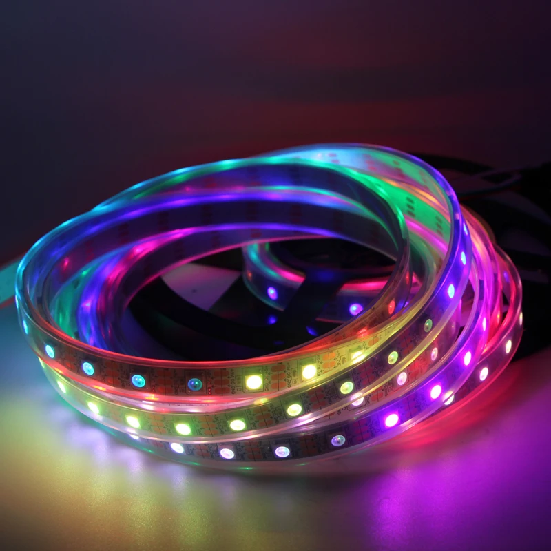
26WS2811, WS2812, WS2812B, WS2813 individually addressable LEDs
![]()
If you have been wondering (being here I know you have, or knew this stuff already) about the wiring and amount of control electronics required to drive the millions of LEDs for modern sport rinks' perimeter displays, these things are how to do it. Each "LED" is actually a package consisting of three LEDs (R,G,B), a capacitor and a rather complex control IC that can from an incoming signal take just its part to control the LEDs and pass the rest to the next ones. This way long chains can be controlled by a single MCU, just need to deliver power to all the LEDs and daisy chain their inputs and outputs together.
Some proper snippets to be added, I'm still a bit puzzled with reliably using 2811 vs 2812 vs 2813 with various libraries and I²S DMA vs bit bang modes. The RX pin used by I²S libraries is in the Wemos tied to the UART, figuring out the best way to make it work properly.
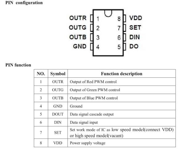
![]() The WS2811 is a LED controller chip, requiring external R,G,B LEDs. At 5 V
uses one LED per channel, at 12 V three LEDs. This is why 12 V VS2811
strips have three RGB leds per IC, and control in those bunches of three
instead of one.
The WS2811 is a LED controller chip, requiring external R,G,B LEDs. At 5 V
uses one LED per channel, at 12 V three LEDs. This is why 12 V VS2811
strips have three RGB leds per IC, and control in those bunches of three
instead of one.![]() WS2812 is basically a 2811 embedded inside a 5x5 mm RGB LED case. Separate power supplies for LEDs and control. Requires external capacitor.
WS2812 is basically a 2811 embedded inside a 5x5 mm RGB LED case. Separate power supplies for LEDs and control. Requires external capacitor.![]() WS2812B is a simplified layout version of the 2812, common power for LEDs and control. Requires capacitor.WS2812B
WS2812B is a simplified layout version of the 2812, common power for LEDs and control. Requires capacitor.WS2812B![]() WS2813 has an internal capacitor, which eases making DIY arrays and
stuff. Also has a safe break feature, that each LED's output is routed
to the next (DIN) and the next over that (BIN), thus one failing 2813
doesn't blank all the successive LEDs.
WS2813 has an internal capacitor, which eases making DIY arrays and
stuff. Also has a safe break feature, that each LED's output is routed
to the next (DIN) and the next over that (BIN), thus one failing 2813
doesn't blank all the successive LEDs.
Resources- WS2811 datasheet: https://cdn-shop.adafruit.com/datasheets/WS2811.pdf
- WS2811 information:https://wiki.hacdc.org/index.php/WS2811_Digital_RGB_LED
- WS2812 datasheet: http://www.alldatasheet.com/datasheet-pdf/pdf/553088/ETC2/WS2812.html
- WS2812B datasheet: https://www.kitronik.co.uk/pdf/WS2812B-LED-datasheet.pdf
- WS2813 datasheet: https://www.element14.com/community/servlet/JiveServlet/downloadBody/82240-102-1-346305/WS2813.pdf
-
27Data output using the LED (or buzzer)
![]()
ESP-12 environment logger blinking its IP address Outputting debug codes, IP addresses etc is generally done using serial console (requiring a computer etc terminal) or a display module (increasing cost, size, power consumption and complexity).
Pretty much every ESP module has at least one LED, so why wouldn't we use that? A single LED isn't the most intuitive display device, but allows showing status codes, or even IP addresses etc as binary codes, which likely aren't that unfamiliar to the average reader. Longer codes can be videoed for easier decrypting, they could be shown at boot or when pressing a GPIO interrupt button.
The LED sure can be replaced by a buzzer, might be handy with the blinkMorseChars() function in case of physical/environmental blindness.
Initialization
#define LED_BUILTIN 2 //Not needed, if the pre-defined value OK
#define LED_REVERSED 1 //Set to one, if logical zero = LED on
setup()
pinMode(LED_BUILTIN, OUTPUT);
Functions (pick the ones needed, often the first one would be enough)
/******* Begin IntBlinker (C) Turo Heikkinen 2019 *******/
// Blink one integer, or some bits of it
// Setting "bits" to >0 will also display leading zeroes
void blinkInt(uint16_t in, uint8_t bits = 0) {//0 = starting from first "1"
  for(int8_t i = (bits ? bits : 16) - 1; i >= 0; i--) {
    uint8_t blinkTime = 250; //On time for "1"
    if((in >> i) & 1)
      bits = 1; //Enable blink
    else
      blinkTime = 50; //On time for "0"
    if(bits || i == 0) {
      digitalWrite(LED_BUILTIN, 1 ^ LED_REVERSED);
      delay(blinkTime);
      digitalWrite(LED_BUILTIN, 0 ^ LED_REVERSED);
      delay(400 - blinkTime); //400 = Time of one bit
    }
  }
  delay(400); //Wait between bytes
}

// A "start bit" to tell when a message starts
void blinkStart() {
  digitalWrite(LED_BUILTIN, 1 ^ LED_REVERSED);
  delay(800); //"Start bit" length
  digitalWrite(LED_BUILTIN, 0 ^ LED_REVERSED);
  delay(200); //Wait before first bit
}

// Blink several integers from an uint array
void blinkIntArray(uint16_t *bytes, uint8_t len, uint8_t bits = 0) {
  blinkStart();
  for(uint8_t i = 0; i < len; i++)
    blinkInt(bytes[i], bits);
}

// Blink a list of integers
void blinkInts(int n, ...) {//n=num of params
  va_list vars;
  va_start(vars, n);
  blinkStart();
  for (uint8_t i = 0; i < n; i++)
    blinkInt(va_arg(vars, uint));
}

// Blink string as morse code
void blinkMorseChars(char * in) {
  const uint8_t codes[] = {31,5,15,5,7,5,3,5,1,5,0,5,16,5,24,5,
    28,5,30,5,1,2,8,4,10,4,4,3,0,1,2,4,6,3,0,4,0,2,7,4,5,3,4,4,
    3,2,2,2,7,3,6,4,13,4,2,3,0,3,1,1,1,3,1,4,3,3,9,4,11,4,12,4};
  for (uint8_t i = 0; i < strlen(in); i++) {
    char c = in[i] - 48; //Start from "0"
    c -= (c > 42) ? 32 : 0; //Fold lowercase on uppercase
    c -= (c > 9) ? 7 : 0; //Pack letters after numbers
    if (c < 36)
      blinkInt(codes[c * 2], codes[c * 2 + 1]);
  }
}
/******* End IntBlinker *******/
Use examples
IPAddress ip = WiFi.localIP(); blinkStart(); //Some data to be expected.. blinkInt(ip[3]); //Often we know the three first digits blinkInts(4, ip[0],ip[1],ip[2],ip[3]); //Full IP address uint16_t intsToBlink[4]={1,2,3,4}; blinkIntArray(intsToBlink,4); if (statusOk) blinkInt(0xff, 3); //3 long blinks else blinkInt(0, 3); //3 short blinks blinkInt(0b111); //Morse "O" blinkInt(0b101); //Morse "K" blinkInt(0b000111000,9); //Morse "SOS" blinkMorseChars("SOS"); //Same, with char breaks -
28ESP-Now
Ability to connect to WiFi infrastructure is cool, but is costly energywise, if you're on batteries. ESP8266 & 32 have a semi-hidden feature called ESP-Now, that allows very quick data transmissions, like 40-50 ms total for booting up and sending data, or 60 Hz or so frequency, if not deep sleeping in between. Sure there is a catch, it is not compatible with WiFi, so you'll need another ESP listening, probably acting as a gateway.
A simple 8266 example for sending and receiving, flash it to two ESPs and pull GPIO12 of the sender one down:
#define SLEEP_SECS 5 //How often to send
#define WIFI_CHANNEL 1
#define PIN_MODE 12 //Pin low = sender mode

extern "C" {
  #include <espnow.h>
}
#include <ESP8266WiFi.h>

uint8_t receiverMac[] = {0x36, 0x33, 0x33, 0x33, 0x33, 0x39}; //Set to something not conflicting other ESP-now systems
uint8_t senderMac[] = {0x36, 0x33, 0x33, 0x33, 0x33, 0x38}; //Can be used to avoid messages from wrong senders
bool MODE_SENDER = 0; //Hardwire role here, if not using GPIO for that

// Add fields to send here
struct __attribute__((packed)) MESSAGE_DATA {
  uint32_t value;
} messageData;

void initVariant() {
  pinMode(PIN_MODE, INPUT_PULLUP);      //Comment these, if hardwiring role
  MODE_SENDER = !digitalRead(PIN_MODE); //Read role from the GPIO
  pinMode(PIN_MODE, INPUT); //No need to heat the internal pull-up resistor anymore

  WiFi.mode(WIFI_AP);
  wifi_set_macaddr(SOFTAP_IF, MODE_SENDER ? senderMac : receiverMac);
}

void sendCallBackFunction(uint8_t *mac, uint8_t status) {
  Serial.printf("\nSent message %u status %u\n", messageData.value, status);
  ESP.deepSleepInstant(SLEEP_SECS * 1000000, RF_NO_CAL);
}

void receiveCallBackFunction(uint8_t *senderMac, uint8_t *incomingData, uint8_t len) {
  //You might want to check sender MAC or a token (first bytes of the data) first to avoid conflicts
  memcpy(&messageData, incomingData, sizeof(messageData)); //Allows using the data outside this function
  Serial.printf("Newmsg %u at %u len %u from mac %02x:%02x:%02x:%02x:%02x:%02x\n", messageData.value, millis() / 1000,len,senderMac[0],senderMac[1],senderMac[2],senderMac[3],senderMac[4],senderMac[5]);
}

void setup() {
  Serial.begin(115200);
  if (esp_now_init() != 0) {
    Serial.println(F("ESP_Now init failed"));
    ESP.deepSleepInstant(SLEEP_SECS * 1000000, RF_NO_CAL);
  }

  if(MODE_SENDER) {
    esp_now_set_self_role(ESP_NOW_ROLE_CONTROLLER);
    esp_now_add_peer(receiverMac, ESP_NOW_ROLE_SLAVE, WIFI_CHANNEL, NULL, 0);
    esp_now_register_send_cb(sendCallBackFunction);
  } else {
    esp_now_set_self_role(ESP_NOW_ROLE_SLAVE);
    esp_now_register_recv_cb(receiveCallBackFunction);
    Serial.println(F("Waiting for messages"));
  }
}

void loop() {
  if (MODE_SENDER) {
    messageData.value = random(0,1000000); //Set values to send here
    esp_now_send(NULL, (uint8_t *)&messageData, sizeof(messageData));
  }

  //Receiver should do all time consuming stuff here
  delay(1000);
}
ESP cookbook
Collecting snippets that can quickly be copied to assemble a program for different sensors etc. Mostly about ESP8266/32 with Arduino IDE.
 The WS2811 is a LED controller chip, requiring external R,G,B LEDs. At 5 V
uses one LED per channel, at 12 V three LEDs. This is why 12 V VS2811
strips have three RGB leds per IC, and control in those bunches of three
instead of one.
The WS2811 is a LED controller chip, requiring external R,G,B LEDs. At 5 V
uses one LED per channel, at 12 V three LEDs. This is why 12 V VS2811
strips have three RGB leds per IC, and control in those bunches of three
instead of one.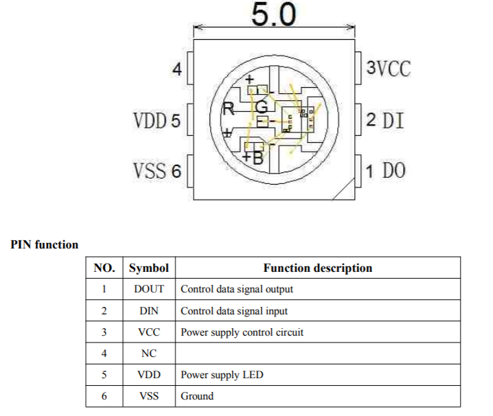 WS2812 is basically a 2811 embedded inside a 5x5 mm RGB LED case. Separate power supplies for LEDs and control. Requires external capacitor.
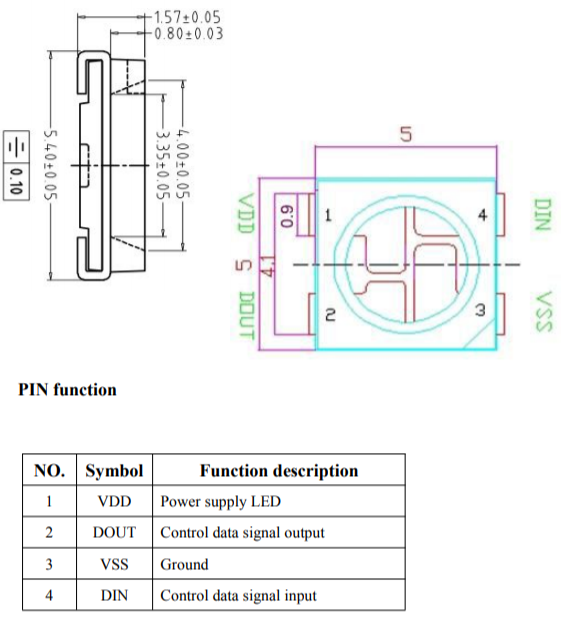 WS2812B is a simplified layout version of the 2812, common power for LEDs and control. Requires capacitor.WS2812B
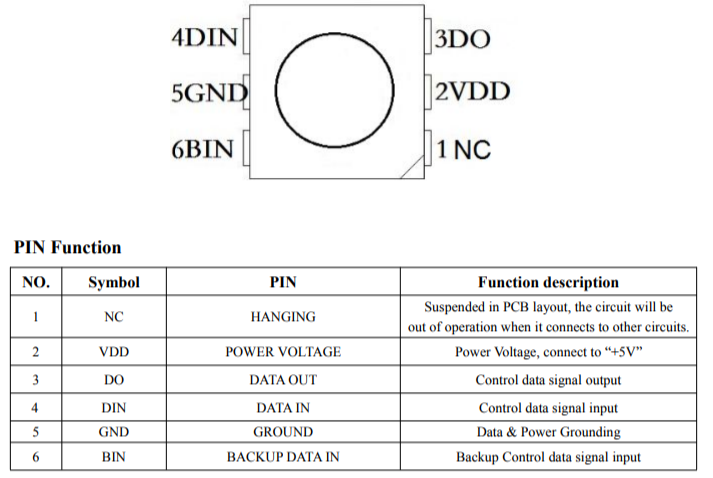 WS2813 has an internal capacitor, which eases making DIY arrays and
stuff. Also has a safe break feature, that each LED's output is routed
to the next (DIN) and the next over that (BIN), thus one failing 2813
doesn't blank all the successive LEDs.
WS2813 has an internal capacitor, which eases making DIY arrays and
stuff. Also has a safe break feature, that each LED's output is routed
to the next (DIN) and the next over that (BIN), thus one failing 2813
doesn't blank all the successive LEDs.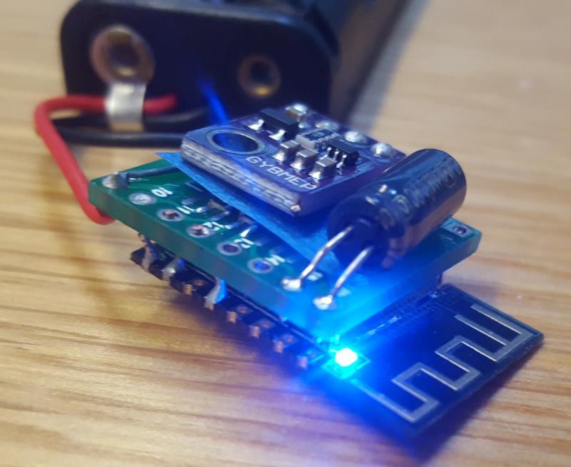
Discussions
Become a Hackaday.io Member
Create an account to leave a comment. Already have an account? Log In.