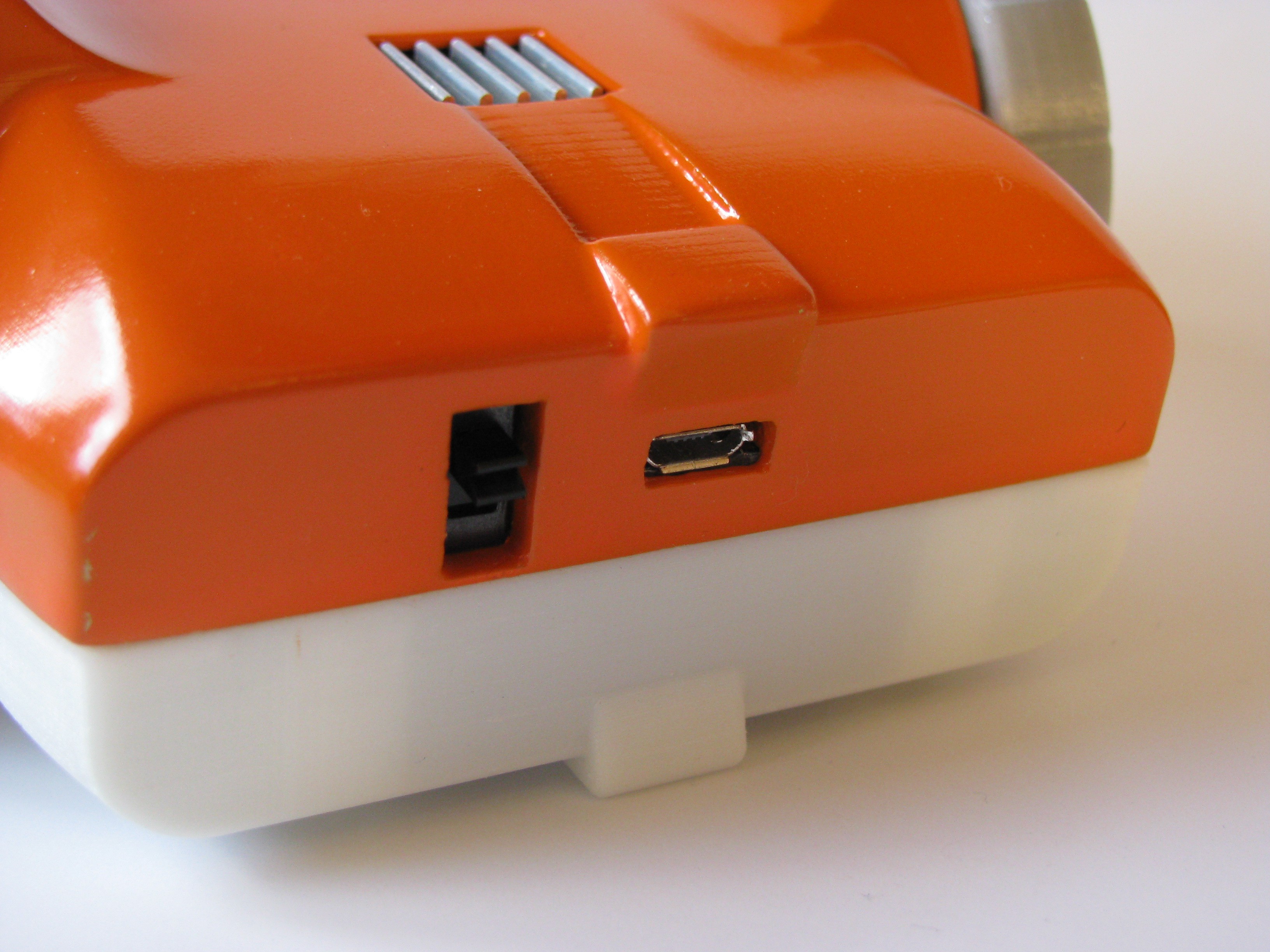
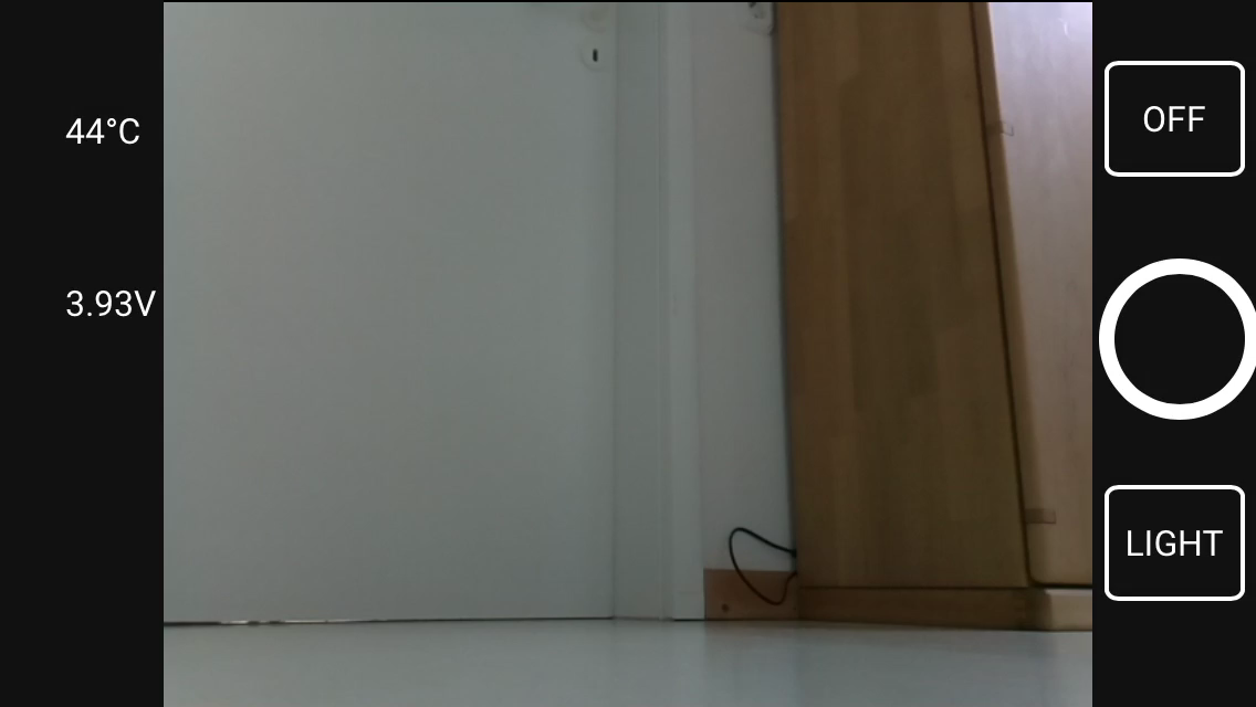
All new features: More battery power, a charging port, battery voltage sensing, headlights, camera mode, safe shutdown, new UI
The new software should work on all existing robots.
When I designed the ZeroBot last year, I wanted to have something that "just works". So after implementing the most basic features I put the parts on Thingiverse and wrote instructions here on Hackaday. Since then the robot has become quite popular on Thingiverse with 2800+ downloads and a few people already printed their own versions of it. Because I felt like there were some important features missing, I finally made a new version of the robot.
The ZeroBot Pro has some useful, additional features:
- Instead of a single battery with a power-bank circuit, the ZeroBot Pro is now powered by two 2600mAh batteries in parallel. Thanks to a cheap TP4056 Micro-USB charger the case does not have to be opened to recharge the batteries. 5V for the Pi and 6V (optional) for the motors are regulated by MT3608 boost converters.
- Thanks to a ADS1115 ADC the Raspberry can measure the battery voltage and display it on the user interface
- The entire user interface has been optimized for various screen sizes. There are now buttons for different functions:
![]()
- A photo button for taking pictures in full resolution. This is not as easy as it appears. The stream has to be stopped to start the raspistill application and then restarts.
- A toggle button to turn the LED headlights on and off. The LEDs are connected via a transistor to an IO pin. (I adopted this idea from franciscorps version of the ZeroBot: https://www.thingiverse.com/thing:2445551)
- Finally there is a shutdown button that turns the Pi off safely after displaying a confirmation prompt. This should prevent the file system from corrupting
- The 3D printed parts have been optimized as well to reduce warping and to fit the front panel more easily.
If you are interested in building the robot, you can head over here for the instructions: https://hackaday.io/project/25092/instructions
The 3D files are hosted on Thingiverse: https://www.thingiverse.com/thing:2800717
Download the SD card image: https://drive.google.com/file/d/163jyooQXnsuQmMcEBInR_YCLP5lNt7ZE/view?usp=sharing
After flashing the image to a 8GB SD card, open the file "wpa_supplicant.conf" with your PC and enter your WiFi settings.
 Max.K
Max.K

Discussions
Become a Hackaday.io Member
Create an account to leave a comment. Already have an account? Log In.
Hello, I build this project but I have to add second joystick for remote servo. Can someone help me?
Are you sure? yes | no
built this whole project yesterday. amazing little thing that the grandkids are going to love when im allowed to see them again. i think i will be making another one so we can race them! one single change id like to make, the steering is a little bit too sharp for little fingers and a small screen. is there any way i can adjust the turning speed?
Are you sure? yes | no
If only 1 battery is used, is it an issue ?
Are you sure? yes | no
How can I make the rover accessible over the web. Through port forwarding or however?
Are you sure? yes | no
Hi! Max,
May I know what's the motor driver you employed in the project? Thank you!
Are you sure? yes | no
Its an L298n, very inexpensive.
Are you sure? yes | no
Would it be possible/easy to use a Raspberry Pi 3 Model A+ instead of the Raspberry Pi Zero W?
I guess I would only need to move the screw holes to accommodate for the size of the Pi 3, right?
Are you sure? yes | no
Im using a 3 Model A +, works fine, but keep in mind im using it in a different form factor. Not sure if it would fit in the original casing.
Are you sure? yes | no
Hi,
Great project!
Why not just use a bigger power bank (5000) or two small power banks? I assume this will simplify things as the charger and the converter will not be required?
Thanks
Are you sure? yes | no
I agree, I've removed the charging and protection modules from a power bank and I am trying to utilize them.
Are you sure? yes | no
Hello, and congratulations for this beautiful robot. I'm trying to buy one for my son. I would like to know with which software you create your command interface. And that file edit, because I would add a button to add a buzzer.
Thank you in advance for your answer.
Are you sure? yes | no
Hi, really cool project. Does it have an option to control robot remotely (via internet)? Smartphone app might be a good option
Are you sure? yes | no
is there a comprehensive parts list for the zero bot pro, I used the pictures and schematic to base the parts off of, but wasn't sure if I missed it. Also what gauge wire is recommended?
Are you sure? yes | no
I have a problem with motors mounting. Motors fit nice into the bottom part, but how do i hold them to their places? When i close the upper part i can move the motor by motor shaft. See video https://www.youtube.com/watch?v=OsIr_eOK-o0
Are you sure? yes | no
Thanks for this awesome project!
I'm a beginner so it may be a simple problem that I am having trouble with but here goes...
From GPIO22 I think that I have set up the resistors and LED's and transistor (at the top of the diagram) correctly, but I dont understand what happens after the LED's, it appears as though I am supposed to connect the positive side of the LED's to the side of the switch ...before... the boost converter lowers the voltage?
I tried this and the CPU of the Raspberry Pi got crazy hot, and does this now every time its connected to power, I'm guessing I broke it due to incorrect wiring?
Are you sure? yes | no
I think something is wrong with the Pro image; there is no "wpa_supplicant.conf" file in boot to edit. I downloaded ZeroBotProWifi.7z twice, used etcher to image it three different times, same result. Any thoughts?
I can use the original SD card image, is it a good workaround to use that and upgrade to the Pro version via the given instructions?
Are you sure? yes | no
Sorry for the late reply. I recently fixed an error in the image file and forgot to add the wpa_supplicant.conf in the end. You can create the file yourself by pasting this into a text file and renaming the file to wpa_supplicant.conf:
country=DE
ctrl_interface=DIR=/var/run/wpa_supplicant GROUP=netdev
update_config=1
network={
ssid="wifi_name"
psk="password"
}
(Insert your own ssid and password of course)
Are you sure? yes | no
I had no idea it was that simple haha. I should have looked on Google for it! Thank you so much for the reply! I will use the new image and see where that gets me, thanks so much!
Do you have any crypto wallet address for donations? I would surely give at least a few bucks towards a good cause, maybe even the Pro V.2 robot!
Are you sure? yes | no
Glad I could help. The fixed image file is online now as well.
If you want to support me, you could leave a tip on Thingiverse. : )
Are you sure? yes | no
Very nice project! I just finished building mine and after modifying pins for the motor driver and the orientation of the camera video in software, everything runs perfectly.
I just used an other step-up module found here::
https://fr.aliexpress.com/item/5PCS-LOT-DC-DC-Converter-3-5V-to-5V-3A-Step-up-Power-Supply-Boost-Module/710951542.html
and plan on using this::
https://fr.aliexpress.com/item/LiPo-Fuel-Gauge-battery-detection-A-D-conversion-IIC-MAX17043/32599314036.html
for battery percentage reading. I prefer this over volts :)
Thanks for this, it's fun to make and hack!
Are you sure? yes | no
For the new sd image, the kernel fails to open, but it still opens the desktop. I can't use a keyboard or mouse. A message pops up telling me to change the password of the pi because the SSH is a security risk. Any suggestions on how to fix these errors?
Are you sure? yes | no
HI love the project and its progress. I just put one together and have a question and issue. The issue I have is control, Left moves reverse, Right moves forward, Up moves right and Down moves left. Is there a way to correct this? It does not seem to matter if its controlled on laptop or phone or the orientation of the phone?
Are you sure? yes | no
Hi, that means the cables to your right motor are flipped. You can solve this by either soldering them the other way or by changing the file app.js in the folder TouchUI: Inside that file you can change the gpio definitions (e.g. B2 = new Gpio(18, {mode: Gpio.OUTPUT});). B1 and B2 should be the right motor, but it could also be A1 and A2.
Are you sure? yes | no
Thanks for that I have resolved this and it works great!!
Are you sure? yes | no
Do you have a list of the electronics and where to get them?
Are you sure? yes | no
There is a list of everything in the instructions: https://hackaday.io/project/25092/instructions
Most parts should be easy to find via ebay/google.
Are you sure? yes | no
Ah man, this update is awesome!
Your case looks simply amazing - the finish is unreal.
I need to get someone to print this and then put one together for my son!
Are you sure? yes | no
Thank you, glad you like it!
Are you sure? yes | no