Bud Bennett
-
Fifth Time is the Charm?
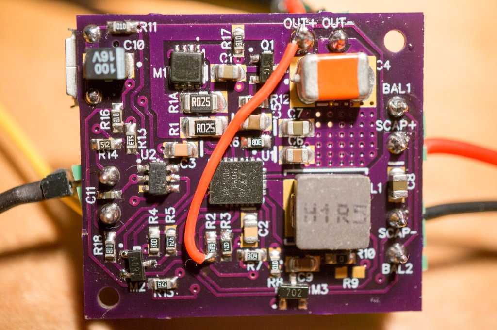
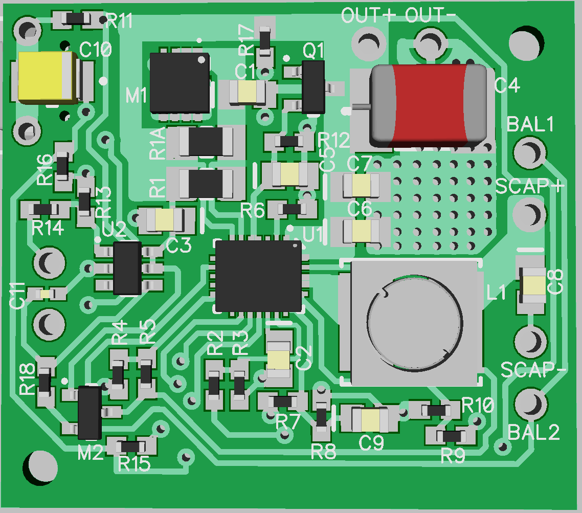
12/14/2019 at 23:12 • 0 commentsI populated one of the three PCBs received from OSH Park a couple of days ago. It is configured for a single supercap. I had to remove the LTC4041, PIC, and M1 from an LG4 PCB to avoid having to buy/reprogram a component for the new PCB. There was a problem with a trace on the LG5 PCB and I had to add a 30AWG wire to correct it. Final board looks like this:
![]()
I've contacted OSH Park about the problem...they refunded the order. But with my ugly fix the board is working as expected. I have tested the UPS with three versions of the Raspberry Pi: RPiZW, RPi2B and RPi1B. The same code works well for all of the tested Raspberry Pi variants. The new code allows the final SCAP voltage to drop to 2.3V (for a single supercap). I found that the SCAP voltage at the end of the shutdown sequence was within a few tens of mV from 2.3V. I left the target SCAP voltage with 2 supercaps at 2.4V since the rate of change is a lot higher when using two smaller supercaps -- a bit of margin to error.
In any case, the UPS is working better in all respects and I'm ready to call it a day and complete this project once again.
-
Raspberry Tests with new python code
12/11/2019 at 05:43 • 0 commentsThe updated LG5 boards just arrived from OSH Park today, so all of these results, such as they are, were obtained with a modified LG4 board.
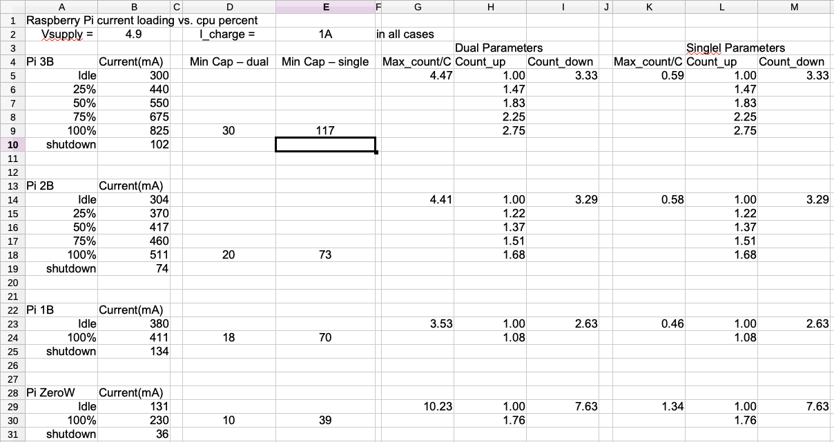
I decided to update the python code that monitors the status of the ups and decides when to shutdown the Pi. I took current load data on alll of the Raspberry Pi units that aren’t currently dedicated: RPi1B, RPi2B, RPi3B, RPiZW. The single-core units, RPi1B and RPiZW, were measured at idle, 100%, and shutdown. The 2B and 3B units were measured at idle, 25%, 50%, 75%, 100%, and shutdown. This is the data that I obtained on the units that I measured.
![]()
All of the RPi models were connected to HDMI, a powered USB expander for the keyboard and mouse, and had a 16GB thumb drive connected to the USB on the RPi (except the RPiZW). The other columns of the spreadsheet calculate the minimum capacitance values required to support the model at max current with dual or single supercapacitors, and the parameters for counting out the period to shutdown as a function of cpu loading.
The new code now takes into account the number and value of supercaps, the Raspberry Pi model, and the loading of the cpu on a dynamic basis in order to determine when to begin the shutdown procedure. The code relies on psutil to calculate the percentage of cpu activity on a second-by-second basis and adjust the time to shutdown accordingly. Since the code is written in python3, the psutil module is installed by:
sudo apt-get update
sudo apt-get install python3-psutilpowerfail.py [Edit 2019-12-14: made a few changes to improve robustness. Improved the calculation to determine time to recharge the supercap if PWRGOOD goes high before a shutdown event. Changed the calculation for a single supercapacitor to allow voltage drop to 2.3V, as long as the current draw is less than 1A. Latest code can be downloaded from the files section of this project.]
#!/usr/bin/env python
'''
This program monitors the status of the PWRGOOD signal from the UPS circuit.
PWRGOOD is normally high. If it goes low then the input power has failed.
This program senses when PWRGOOD falls and then samples it once/second. An
accumulator counts up by 1+(cpu_pc * (imax/idle - 1)) if power is bad and
counts down by icharge/idle if power is good. This accounts for the difference in
supercap charge current vs. load current.
If the accumulator exceeds count_max then it signals the UPS to disconnect the
power by asserting SHUTDOWN. This will still cause a shutdown condition even when
the power is cycling on and off. After it commits the hardware to shutdown it also
sends a shutdown command to the Linux system. The UPS will hold power up for 20 seconds
after it receives the SHUTDOWN signal, which allows the Pi to enter a shutdown state
prior to power removal.
'''
import RPi.GPIO as GPIO
import time
import logging
import logging.handlers
import psutil
from math import sqrt
import subprocess, sys

#--logger definitions
logger = logging.getLogger(__name__)
logger.setLevel(logging.INFO)  # Could be e.g. "TRACE", "ERROR", "" or "WARNING"
handler = logging.handlers.RotatingFileHandler("/var/log/bud_logs/ups_mon.log", maxBytes=10000, backupCount=4) # save 4 logs
formatter = logging.Formatter('%(asctime)s %(levelname)-8s %(message)s')
handler.setFormatter(formatter)
logger.addHandler(handler)

class MyLogger():
    '''
    A class that can be used to capture stdout and sterr to put it in the log

    '''
    def __init__(self, level, logger):
            '''Needs a logger and a logger level.'''
            self.logger = logger
            self.level = level

    def write(self, message):
        # Only log if there is a message (not just a new line)
        if message.rstrip() != "":
                self.logger.log(self.level, message.rstrip())

    def flush(self):
        pass  # do nothing -- just to handle the attribute for now


def powerfail_detect(count_max, idle, imax, ichrg, cap_num, cap_value):
    # if the count exceeds 20 the system will shutdown.
    count = 0
    Vsys = 5.0
    if cap_num == 2:
        cap = cap_value/cap_num
        Vmax = 4.5
    else:
        cap = cap_value
        Vmax = 2.68
    pwr_flip = False
    while (count < count_max):
        cpu_pc = psutil.cpu_percent(interval=1)/100 # get cpu percent over the last second
        if (GPIO.input(PWRGOOD)):
            if (pwr_flip):
                logger.info("Power is good")
                logger.info("Count = {}".format(int(count)))
                # calculate time to recharge supercap
                watt_sec = 1.1 * Vsys * idle/1000 * count  # assume booster is 90% efficient
                #logger.info("watt_sec = {}".format(watt_sec))
                count_dn = count/(cap*(Vmax - sqrt(Vmax*Vmax - 2*watt_sec/cap))/(ichrg/1000))
                if count_dn < 1:
                    count_dn = 1
                #logger.info("Count_dn = {}".format(count_dn))
            count -= count_dn
            pwr_flip = False
            if (count <= 0):
                logger.info("Returning to normal status")
                return
        else:
            if (not pwr_flip):
                logger.info("Power has failed")
            count += 1+(cpu_pc * (imax/idle - 1)) # load current dependent
            pwr_flip = True
    logger.info("powerfail iminent...shutting down the Pi!\n")

    GPIO.setup(SHUTDOWN,GPIO.OUT)
    GPIO.output(SHUTDOWN,0)
    time.sleep(0.1)
    GPIO.output(SHUTDOWN,1)
    time.sleep(0.1)

    p = subprocess.Popen(["sudo","shutdown","-H","now"])  # shutdown the Pi
    GPIO.cleanup()
    haltandcatchfire()
    return

def haltandcatchfire():
    while True:
        time.sleep(10) # hang here until poweroff
    return

# If this script is installed as a Daemon, set this flag to True:
DAEMON = True # when run as daemon, pipe all console information to the log file
# --Replace stdout and stderr with logging to file so we can run it as a daemon
# and still see what is going on
if DAEMON :
    sys.stdout = MyLogger(logging.INFO, logger)
    sys.stderr = MyLogger(logging.ERROR, logger)

# get Raspberry Pi model information
p = subprocess.Popen(["cat","/proc/device-tree/model"], stdout = subprocess.PIPE)
model = p.communicate()[0].decode("utf-8")

# set UPS parameters
CAP_NUM = 1
CAP_VALUE = 100  # value of single cap, or each of dual caps
ICHRG = 1000  # charge current in mA
if ("Raspberry Pi Zero W" in model):
    logger.info(" ")
    logger.info("Setting UPS parameters for {}".format(model))
    IDLE = 130
    IMAX = 225
    SEC2SHUTDN = 20 # seconds required for Pi to complete shutdown
elif ("Raspberry Pi Model B" in model):
    logger.info(" ")
    logger.info("Setting UPS parameters for {}".format(model))
    IDLE = 380
    IMAX = 411
    SEC2SHUTDN = 20 # seconds required for Pi to complete shutdown
elif ("Raspberry Pi 2 Model B" in model):
    logger.info(" ")
    logger.info("Setting UPS parameters for {}".format(model))
    IDLE = 304
    IMAX = 511
    SEC2SHUTDN = 20 # seconds required for Pi to complete shutdown
elif ("Raspberry Pi 3 Model B" in model):
    logger.info(" ")
    logger.info("Setting UPS parameters for {}".format(model))
    IDLE = 300
    IMAX = 825
    SEC2SHUTDN = 20 # seconds required for Pi to complete shutdown
else:
    logger.error("No UPS parameters for {}\n\tUPS is disabled.".format(model))
    haltandcatchfire  # sleep instead of terminate to avoid daemon restart

if (CAP_NUM == 2):
    # how many seconds of power loss before the Pi shuts down if idle
    COUNT_MAX = 0.9*CAP_VALUE/CAP_NUM * (4.5**2 - 2.4**2)/(2*1.1*4.9*IDLE/1000) - SEC2SHUTDN
elif (CAP_NUM == 1):
    COUNT_MAX = CAP_VALUE/CAP_NUM * (2.68**2 - 2.3**2)/(2*1.1*4.9*IDLE/1000) - SEC2SHUTDN
else:
    logger.error("Invalid number of supercapacitors -- UPS is disabled.")
    haltandcatchfire()

# set the GPIO pin assignments
PWRGOOD = 23
SHUTDOWN = 24

# configure the GPIO ports:
GPIO.setmode(GPIO.BCM)
# PWRGOOD is an input with weak pullup
GPIO.setup(PWRGOOD, GPIO.IN, pull_up_down = GPIO.PUD_UP)

try:
    logger.info("Enabled")
    logger.info("\tNumber of Supercaps: {}".format(CAP_NUM))
    logger.info("\tSupercap value: {}F".format(CAP_VALUE))
    logger.info("\tSupercap Charging current: {}mA".format(ICHRG))
    logger.info("\tLoad Current at Idle: {}mA".format(IDLE))
    logger.info("\tMax Load Current: {}mA".format(IMAX))
    logger.info("\tSeconds of Power Loss at Idle: {}".format(int(COUNT_MAX)))
    if (COUNT_MAX < 5 or (IMAX > 1000 and CAP_NUM == 1)):
        logger.error("UPS is unable to support {} with given parameters.".format(model))
        haltandcatchfire()
    while True:
        time.sleep(1)
        if (not GPIO.input(PWRGOOD)):
            powerfail_detect(count_max=COUNT_MAX, idle=IDLE, imax=IMAX, ichrg=ICHRG,
                             cap_num=CAP_NUM, cap_value=CAP_VALUE)

except Exception as e:
    print (e)
    GPIO.cleanup()  # clean up GPIO on CTRL+C exit
fourcores.py -- cpu loading is changed by varying the number in the for loop
#!/usr/bin/env python3

import time
import datetime
import multiprocessing

def busy():
    junknum = 0
    while True:
        junknum += 1

if __name__ == '__main__':
    jobs = []
    for i in range(4):
        p = multiprocessing.Process(target=busy)
        jobs.append(p)
        p.start()
I tested the code on the modified LG4 board, with two 25F supercaps, by running the fourcores.py program with a varying number of cores engaged and then pulled the power adapter from the wall. In some cases, if there was time, I would start and stop the fourcores program to see if powerfail.py could accurately predict the point at which to shutdown the system -- how close it would come to 2.5V at SCAP+. The code appears to work as intended on the limited number of Raspberry Pi models that I tested -- RPiZW and RPi2B. If it shut down too early, then the UPS would just hold up the power for several seconds until the SCAP voltage fell below 2.45V. It did not shutdown too late during my rather relaxed testing. I'll perform more thorough testing when the LG5 board is built.
-
You Get What You Pay For
12/04/2019 at 23:39 • 0 commentsAfter the failure of the eBay 100F supercaps, I plunked down a few $$ and ordered some from Digikey:
100F +30/-10% manufactured by AVX. 8mΩ ESR. $8/each.
50F +30/-10% manufactured by Illinois Capacitor. 15mΩ ESR. $4/each.
25F +30/-10% manufactured by Eaton. 27mΩ ESR. $4.35/each.
Executive summary: they all performed as expected.
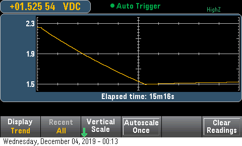
The discharge recovery of the 100F supercap was the worst:
![]()
The snap-back was 25mV after more than nearly 7 minutes of rest (and still rising).
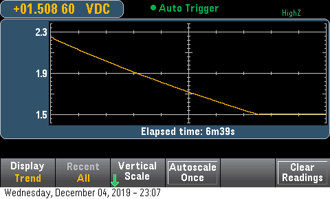
The 50F supercaps were stellar -- less than 10mV snap back (but I think they have higher leakage current):
![]()
![]()
The 25F supercaps were very good as well:
![]()
![]()
All of these supercaps would work well in the UPS. Real world testing next.
-
SuperCapacitor Quality Issues
11/25/2019 at 23:33 • 0 commentsI have purchased three sets of supercapacitors over the last few years. The first two pairs of Supercaps were 350F and 400F units that I bought directly from Digikey. I believe that they were priced somewhere around $12 per supercap (here's a link to the Digikey webpage for the 400F unit). The last two pair of 100F supercaps I bought from eBay, for about $3 per pair. I thought that the eBay stuff was a great deal...until today.
I was attempting to test the 100F supercaps in a dual supercap UPS configuration and write some new code for the UPS in general. I was getting squirrelly results. The UPS would shutdown properly, but after a few minutes it would attempt to turn on the booster, which would cause the Raspberry Pi to begin its boot sequence, but there wasn't enough juice remaining in the supercaps and the output voltage collapsed after a few seconds. This process would repeat every few minutes for what seemed like hours.
Bad Supercaps
I noticed that there was a significant difference between the two supercap voltages: 1.5V and 1.1V. At the end of each false startup attempt the larger voltage would decrease by less than 100mV, but the smaller voltage dropped to about 0.8V but then climbed slowly back until the total of the stack reached 2.65V and the LTC4041 would fire up the booster again. This behavior (behaviour?) was not supposed to happen.
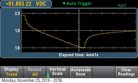
I extracted the two 100F supercaps from the breadboard and charged each of them with a power supply to 2.25V with a current limit of 0.5A. I let the charge current drop below 10mA and then I discharged each capacitor with a 10Ω resistor to 1.5V. Here are the results SCAPB (the bad one):
![]()
SCAPB dropped to 1.5V in about 2 minutes. Note the large step at the beginning of the discharge and recovery cycles. The voltage eventually recovered past 2.0V after a 20 minute wait.
SCAPA faired better:
![]()
SCAPA has a much smaller step at the beginning of the discharge, takes longer to reach 1.5V, and recovers by only 165mV (it was still increasing after 22 minutes). But even this performance is pretty bad -- two supercaps with this behavior would still creep up enough to cause the LTC4041 to enable the booster when it should not.
So I dug one of the 400F supercaps out of a junk box and repeated the experiment -- this time using a 2Ω load for discharge:
![]()
This is what the behavior should look like. There is a sharp drop when the >1A load is applied -- attributed to the ESR. There is another sharp rise when the load is removed -- ESR again. But there is no significant ballooning of the voltage afterward.
I'm tempted to spend a few $$ to obtain some legitimate supercaps in lower Farads to see if there is a difference between Digikey and eBay. I need a 100F supercap ( a real one...not from eBay) to power my heating system. I also would like to see how a couple of 20F supercapacitors from Vishay (Digikey) compare to the eBay stuff. Stay tuned.
-
Unintended Consequences
11/19/2019 at 17:25 • 0 commentsI did not understand all of the implications of changing the PIC code to monitor the SCAP voltage. I was putting final touches on the new design when I started thinking about how it would work if the input power was applied while the UPS was in the delay period after the Raspberry Pi issued a SHUTDN command to the UPS. Since the PIC is now monitoring the SCAP voltage it will not shutdown the LTC4041 charger or booster if the input power is reapplied -- the LTC4041 will begin charging the supercapacitor and the SCAP voltage won't drop below the cutoff threshold. Therefore the RPi will just hang in a shutdown state as long as power is applied.
My solution was to add M3 to force the LTC4041 into a powerfail condition after the RPi asserts the SHUTDN input. This will prevent the supercap from charging and allow the UPS to complete its booster/discharge cycle before removing power to the RPi.
![]()
It is not a perfect solution. It might be subject to noise, but I'm hoping that the deglitching in the PIC will eliminate false hits. If M3 gets a short noise pulse it will cycle the UPS to provide power for a short time -- the RPi should ride through that without issues.
The addition of M3 to the PCB layout was easier than I expected.
![]()
Unfortunately, I will now get two PCBs from Osh Park...
More Consequences:
The addition of M3 only works if the RPi keeps the SHUTDN input high during and after its shutdown or poweroff. There are methods to force this in software, but I not a trusting guy when it comes to system software not changing over long periods.
I came up with a solution in firmware (it's not software, is it?) Since the gate of M3 is connected to the PIC RA0 pin I could change the pin to be an output and force VDD, 5V, on the gate of M3 after the PIC had committed to shutdown. The 1k series resistance, R14, would prevent the RPi from changing the voltage at RA0. It only takes two lines of assembler code:
bcf TRISA, 0 ; make RA0 an output
bsf PORTA, 0 ; latch RA0 high to keep LTC4041 in powerfail mode.This is much simpler, and more robust over time, than messing with the GPIO settings during/after shutdown/poweroff. I will update the code in the files section. If it doesn't work for some reason I'll edit this log with an explanation.
Note: this might require a change to the values of R13 and R14 to prevent a latchup condition in the RPi when current is forced into the GPIO pin.
Breadboard Learning[2018-11-20]:
I decided that it might be instructive to take my only unused LG4 module and add the new components to see if there was anything else I might have missed. I had some TO92 2N7000 FETs in a box somewhere that could be used. I programmed a PIC10F322 SOT-23-6 package to replace the PIC10F202. I did not add C11, partly to see how good the noise immunity was and partly because it was difficult to add to the tenuous connection already tied to the PIC's AN2 input.
The first thing I did was reconfigure the UPS for two 100F supercaps and test for functionality. The SCAP voltage climbed slowly to 4.55V and stayed there. When I removed the input power the output voltage dropped from 5.1V to 4.84V, with a pretty light load of only 22Ω. The voltages on the supercaps was within 20mV during charging, so the balancing seems to work.
I then added all of the new components and applied 5.2V to the input, but this time I did not allow it to charge SCAP to 4.55V -- only to about 3V to keep the discharge time short with a 22Ω load. When I removed the input power the output again dropped to 4.84V and remained at that potential. The SCAP voltage dropped to 2.45V when the booster was disabled and the output voltage dropped to zero. I noticed that the SCAP voltage recovered to 2.55V after the load was removed, but the LTC4041 did not restart the booster after the 7 second disable period ended.
I performed several tests to see if there were any other unpredicted responses of the UPS to various stimulus. Most importantly, the UPS cycled properly when the input voltage was removed, the SHUTDN input activated, and then the input voltage re-applied before the 20 second one-shot period ended. This gives me hope that it will operate properly when a Raspberry Pi is used as a load.
More Breadboard Learning[2018-11-21]:
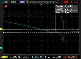
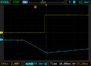
I was worried about the voltage recovery on SCAP after the load was removed, as evidence of the 100mV recovery when only a 22Ω load (220mA) was used. Today I connected a 4Ω load (1.21A) to the output, charged the 2-100F supercap stack all the way to 4.55V, and let it stay in steady state to cool down the LTC4041 a bit. I then disconnected the power and activated the SHUTDN pin shortly afterward. Here's what the voltages at OUT+ (CH1) and SCAP (CH2) looked like:
![]()
I triggered the scope just prior to removing power. The output is very steady until the booster is shutdown when the SCAP voltage touches 2.44V. The SCAP voltage immediately bounces back and climbs during the 10 second period when both CHGEN_ and BSTEN_ are above 1.4V. When CHGEN_ and BSTEN_ fall below 1.4V the voltage at SCAP has climbed to nearly 3V and the booster is turned back on for a short period until the SCAP and VSYS voltages fall below the max(SCAP,VSYS) under-voltage lockout of 2.5V. By that time the SCAP voltage has decreased below 2.5V and the booster is not re-enabled (at least not during the observed interval).
This may appear to be problematic, but I don't believe that it is. In a normal situation the Raspberry Pi will enter a low power shutdown or poweroff condition before the PIC instructs the UPS to disconnect the booster. Therefore, the snapback of VSCAP will be on the order of 100mV, instead of the 500mV exhibited by this test.
The VSCAP snapback can be managed further by using short leads on the supercaps (in this instance the leads were about 100mm long), and using supercapacitors with very low ESR. I bought these 100F supercaps from eBay, so I don't have any idea what their ESR specification is, but my perception is that it is not good. A short survey of 100F supercapacitors offered by Digikey shows a range of 8mΩ to 30mΩ. Get the 8mΩ stuff.
-
PIC Code for 2 Supercapacitor Stac
11/18/2019 at 03:04 • 0 commentsIt took a while to get this done. Apple recently updated its OS to 10.15 - Catalina - and that threw a monkey wrench into the works. Microchip’s MPLABX software is 32-bit software that Apple had declared “persona non grata”. It doesn’t work on my iMac anymore. I had to install the MPLABX software on my Parallels incantation of Windoze 10, which went smoothly, but even afterward MPLABX refused to work with the old files since they did not conform to Windoze path naming conventions. I was forced to move the Microchip design files onto the Parallels partition in order for the software to cease its complaints.
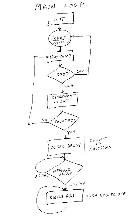
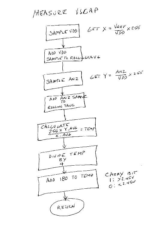
Enough of that. I managed to get the new code for the PIC10F322 working in spite of the Microchip software’s limitations. The changes from the PIC10F202 are significant. Here’s the flowchart for the 322:
![]()
Most of this is the same as the PIC10F202 program. The RA0 input is the shutdown command from the Raspberry Pi. The code requires it to be asserted for 5 continuous samples, 10ms apart, before committing to a shutdown after a 20 second delay. The only addition is to monitor the voltage on the supercapacitor stack and prevent shutdown of the LTC4041 until the voltage at SCAP has decreased below 2.5V. Even so, the code expanded dramatically. I’m kind paranoid about stuff not working in noisy environments, so I built in a few safeguards. All of the measurements are averaged via an 8-sample rolling average. This creates a bit of delay, but also reduces any interference or noise by a factor of nearly 3-fold. The MEASURE FSCAP block contains a bit of code:
![]()
The PIC10F322 has an 8-bit ADC, but it is referenced to VDD. It has an internal voltage reference, but the ADC can only use it as a in input. Therefore, in order to get rid of the VDD sensitivity, the ADC must take two measurements: one of the internal reference voltage wrt VDD, and another of the desired input voltage wrt VDD. The first measurement must be divided into the second to eliminate VDD. But...it's difficult to divide without floating point arithmetic, so I had to be a bit creative. Here's the math:
X = Vref/VDD*255
Y = Vin/VDD*255
256* Y/X = Vin/Vref * 256
I figured out that the result of the division had to be multiplied by 2^8 (256) in order to maintain the fixed point arithmetic of the division. So a ratio of 1 is equal to 255. Any result above 255 is more than unity and below 255 is less than unity. I found a PIC routine on the internet here that accomplishes this nicely. I used it almost word for word.
I also found that I needed to divide the result by a factor of 4 in order to keep it within an 8-bit range. The result of the division creates a 2-byte result, if the ratio is larger than unity. Dividing by 4 keeps it within 8-bits over the expected range. To create a threshold for high or low input value I added a constant to the divider result and checked for the overflow in the carry bit.
I programmed an 8-pin DIP version of the PIC10F322 and tested it in on the bench. The first item was the 20 second delay prior to shutdown:
![]()
Close enough. The remaining tests involved determining the accuracy of the VSCAP measurement vs. VDD:
VDD AN2
4.60V 2.442V
5.00V 2.442V
5.40V 2. 447V
That's pretty good! Better than expectations, considering the resolution of the 8-bit ADC is about 20mV.
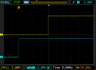
The last test was to determine what the latency in detecting the SCAP voltage falling through the threshold, given all of the mathematical processing involved:
![]()
It's not bad -- less than 10ms to detect that SCAP is falling below the threshold. The trace above shows the RA1 output responding to a falling voltage on AN2. The voltage dropped 100mV, from 2. 525V to 2.425V.
It appears the PIC code is good enough to prove the concept. I'll be ordering new PCBs from OSH Park tomorrow. The PIC code is posted in the files section of this project.
-
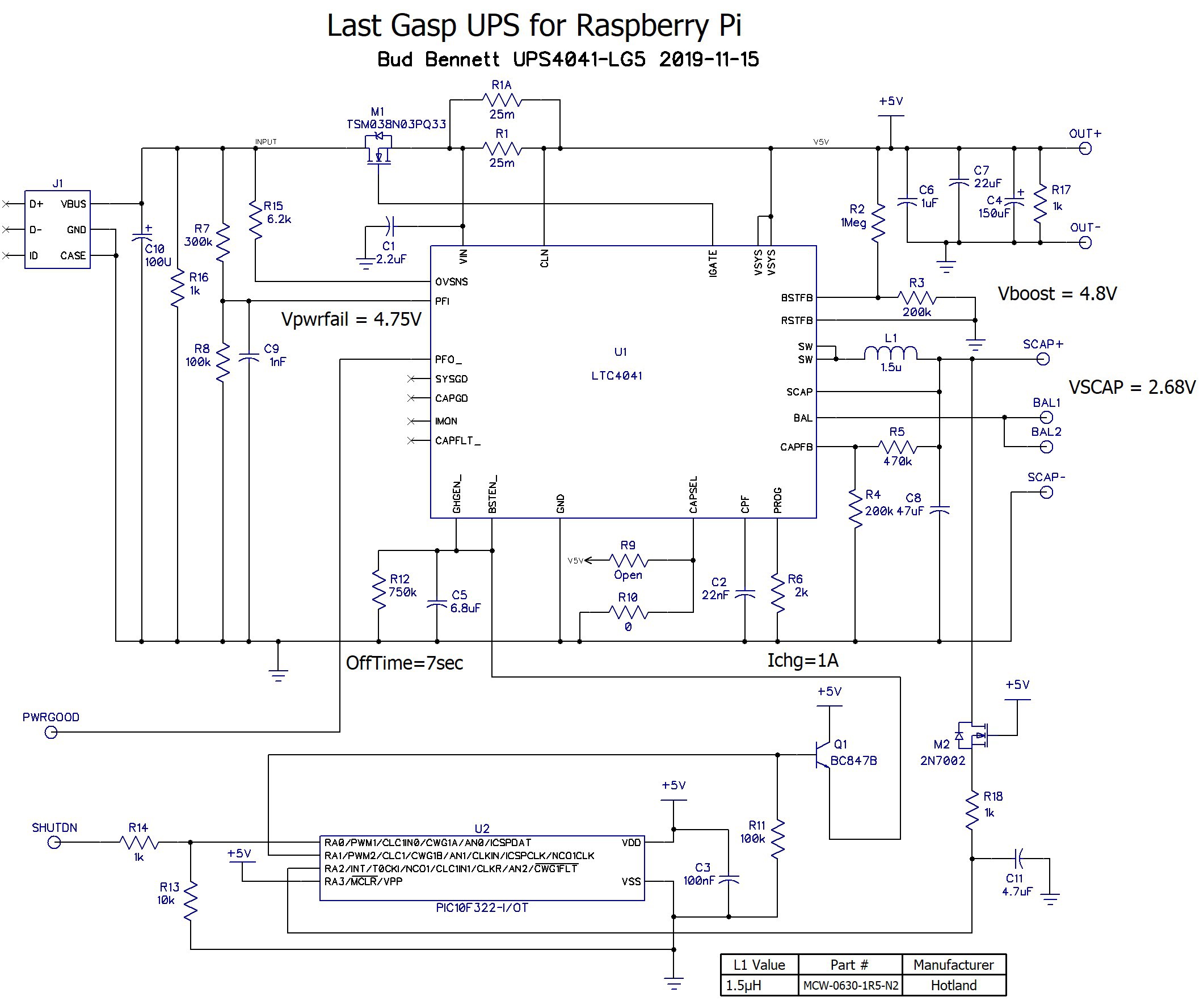
Modifications for a Stack of 2 Supercapacitors
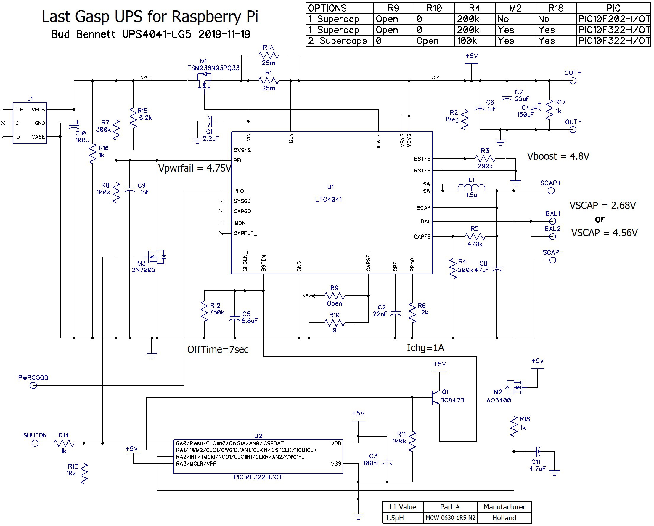
11/15/2019 at 21:40 • 0 commentsI've recently been working with Xenon462, who wants to use this design with a stack of 2 supercapacitors. It got me thinking about how to overcome the problem of insuring that the voltage on SCAP is below 2.5V before shutting down the LTC4041 by yanking on the BSTEN_ and CHGEN_ pins. I came up with this possible solution:
![]()
The changes to the previous design (the UPS4041-LG4) are the substitution of the PIC10F202 with a PIC10F322 and the addition of R18 and M2. The PIC10F322 has an internal 8-bit ADC that is assigned to RA2/AN2 to monitor the voltage at SCAP. R18 and M2 switch the SCAP voltage to the PIC to prevent unwanted current drain from the supercapacitor stack when there is no power applied.
The PIC code will be modified so that the RA1 output won't be asserted until the shutdown period has expired and the voltage at RA2 is below 2.5V. This will insure that the LTC4041 wont restart the booster when the voltage at BSTEN_ and CHGEN_ fall below their 1.4V threshold, unless there is input power present.
[Edit 2019-11-17: Added C11 as insurance.]
A side benefit to this design is that it will revert back to the UPS4041-LG4 design by depopulating R18 and M2, and substituting the PIC10F202 as U2 (it is pin-compatible.)
The changes to the PCB were straightforward and increased the size by about 0.075 inch in one dimension.
![]()
I'll be ordering new PCBs after completing the new PIC code.
-
Completed.
08/22/2019 at 20:47 • 1 commentNo Drama. I installed the latest UPS version into my Heating System/Well Monitor enclosure. I was pretty confident that I would work as designed so the only testing that I employed was to disconnect the wall adapter and then reconnected after a couple of seconds. The system didn't show any signs of distress and the log file registered the event:
2019-07-28 12:48:05,181 INFO Enabled
2019-07-28 13:17:12,174 INFO Power has failed
2019-07-28 13:17:15,181 INFO Power is good
2019-07-28 13:17:16,185 INFO Returning to normal status
2019-08-15 23:42:13,903 INFO Power has failed
2019-08-15 23:42:14,909 INFO Power is good
2019-08-15 23:42:14,912 INFO Returning to normal status
2019-08-16 09:39:35,642 INFO Power has failed
2019-08-16 09:39:44,661 INFO powerfail iminent...shutting down the Pi!
2019-08-16 09:40:47,147 INFO Enabled
Since I installed it, on 2019-07-28, there have been two power loss events recorded in the log. One event was only a second in duration so the UPS did not have to shut down the RPi (but my hot tub and range needed some service.) The second outage was long enough to cause a shutdown, but it performed as designed.
At this point I'm marking this project as completed.
-
Testing With Raspberry Pi as Load
01/10/2019 at 22:55 • 0 commentsIt took longer than expected to get results from using Raspberry Pi 2 and ZeroW. I first pugged in the RPi2, let the supercap charge and then pulled the wall wart. The red power light on the RPi2 began to flash hysterically and the dreaded lightning bolt appeared on the display. Something was wrong with the voltage delivered to the Pi. I measured 4.81V between the OUT+ and OUT- terminals on the UPS, but the PI was getting around 4.7V. It was that damn pink micro-USB cable that I got from the dollar store (for a dollar!). The power leads on that cable were pretty small -- 30 or 32 AWG. I did not want to cut into any of my other micro-USB cables, so I ordered a set of six micro-USB cables, 12 inches long, for $7 from Amazon. They arrived today.
I cut the USB type-A connector off the end of the cable and trimmed off the shielding and the unnecessary data wires. The power wires did look beefier. Substituting the new black power cable for the cheap(er) pink cable fixed the problem. I got a flash from the RPi2's red power LED when the AC adapter was disconnected, but the LED stayed on after that, and no lightning bolt appeared on the screen. I the ran the RPi2 with all 4 cores at 100% without issue. The 100F supercap voltage, after going through 15 seconds of waiting and then 20 seconds of shutting down, was 2.3V -- very acceptable.
I also tested the UPS with the Raspberry Pi ZeroW. The current drain is quite a bit lower -- the UPS can supply power to the ZeroW for 35 seconds (using a 100F supercap) before having to enter the shutdown sequence. I tried all of my various AC adapters to see if the dreaded relaxation oscillation would return, but the UPS reliably applied power and dutifully shutdown without incident, independent of the AC adapter.
I'm very close to the end of this project. The only task remaining is to swap the current UPS for this new UPS in my heating system controller. Since it is the middle of winter, and I'm a bit risk averse, that task will have to wait until warmer weather.
OLD vs. NEW:
Just for grins and giggles I took a photo of the first version of the UPS next to the latest version.
![]()
Some items of note:
- The first version did provide 2.5A from a single supercap charged to 2.7V. The latest version can't do that -- it requires a stack of 2 supercaps to output 2.5A (per spec).
- There is no trim pot on the new version -- a savings of around $1 (and board space).
- The new version can charge the supercap much faster without heating the PCB too much since it uses a switched-mode charger. The old version used a linear charger with foldback current limit.
- Input power jack. Old -- barrel jack. New -- micro USB.
- The new version is less susceptible to noise between the Raspberry Pi and UPS. The PIC SHUTDN input noise rejection seems to be working.
- The new version uses a synchronous switcher for both charging and booster -- lower power dissipation in both cases.
- The old version required nearly 4 hours to populate the PCB. I can populate the new board in less than 1 hour.
-
PIC Code
01/06/2019 at 14:59 • 0 commentsThe assembler code for the PIC10F202 is below. I will also place the hex file for programming it in the files section of this project. The main body is only 21 lines of code. The comments should clearly document what is going on, but here's an overview:
- Setup I/O and watchdog timer.
- Sample SHUTDN pin every 10ms.
- SHUTDN must be high for 5 consecutive samples to be considered "HIGH". This is a noise filter.
- If SHUTDN is high, then delay for 20 seconds and set the GP1 high for 750µs, which disables the LTC4041.
- Loop forever until power is cut by the LTC4041.
; WARNING!!! Don't erase this part before programming. It will erase the
; calibration value stored in 0x01ff.

; PIC10F202 Configuration Bit Settings

; Assembly source line config statements

#include "p10f202.inc"

; CONFIG
; __config 0xFFFB
 __CONFIG _WDTE_ON & _CP_OFF & _MCLRE_OFF

 ; General Notes:
 ; Internal oscillator is 4MHz (1MHz system clock). No external
 ; oscillator needed.
 ; Watchdog timer is set for 18ms x 16 = 288ms.
 ; Only 2 stack registers. Can't call more than 1 nested subroutine.

 ; Pin Assignments:
 ;  1 - GP0: SHUTDN input
 ;  2 - VSS
 ;  3 - GP1: Shutdown output to the base of Q1
 ;  4 - GP2: unused. Set as output.
 ;  5 - VDD
 ;  6 - MCLR_, GP3: unused. tied to VDD in circuit.


;***** Define addresses of the General Purpose Registers ****
; 24 general purpose registers available starting at 0x08
COUNT1    equ 0x08    ;First counter for delay loops
COUNT2    equ 0x09    ;Second counter for delay loops
COUNT3    equ 0x0a    ;Third counter for delay loops
SCRATCH    equ 0x0b    ;Scratchpad variable for everthing else.

    org    0x0000          ; processor reset vector

    movwf    OSCCAL        ; load the calibration value into the OSCCAL reg.

;**** Disable unused peripherals ****
    movlw    b'11001100' ; disable Wake on Change, disable Weak pullups,
    OPTION                ; internal clk -> Timer0, Timer0 source edge don't care,
                ; Prescaler Assignment -> WDT, Prescaler = 16

;**** Setup GPIO inputs/outputs ****
    movlw    b'00000000' ; load GPIO register before TRIS assignment
    movwf    GPIO
    movlw    b'00001001' ; set GP1 & GP2 as output, all others are inputs
    TRIS    GPIO

Start
    clrwdt            ; reset watchdog
    call    Delay10ms
    btfss    GPIO, 0        ; sample SHUTDN input every 10ms
    goto    Start        ; back to START if SHUTDN = 0
    movlw    d'5'        ; number of samples to deglitch SHUTDN input.
    movwf    COUNT3
Sample    call    Delay10ms
    btfss    GPIO, 0
    goto    Start        ; back to START if SHUTDN = 0
    decfsz    COUNT3, 1   ; SHUTDN must be high 5x in a row
    goto    Sample
    clrwdt            ; clear the watchdog
    call    Delay20        ; commit to shutdown at this point. Wait 20 sec.
    bsf    GPIO, 1        ; set the shutdown output high
Stuck    clrwdt            ; reset watchdog
    goto Stuck        ; infinite loop until power is cut


;**** subroutines begin here ****
Delay1                ; total count = 1Meg = 1 second
    movlw    d'8'        ; put 8 into COUNT3
    movwf    COUNT3        ; COUNT3 x (COUNT1 x 3 + 3)(COUNT2 + 5) = 1001472
    movlw    d'255'        ; put 255
    movwf    COUNT1        ; into COUNT1
Loop2    movlw    d'158'        ; put 158
    movwf    COUNT2        ; into COUNT2

Loop1    decfsz    COUNT1,1    ; counts down from 255
        goto    Loop1       ;
        decfsz    COUNT2,1    ; counts down from 158
    goto    Loop1        ;
    clrwdt            ; clear the watchdog timer every 125ms
    decfsz    COUNT3,1    ; counts down from 8
    goto    Loop2        ;
    RETLW    0

Delay10ms            ; delay = 1us x (255x3+3) x (8 + 5) = 9.98ms
    movlw    d'255'
    movwf    COUNT1
    movlw    d'8'
    movwf    COUNT2
Loop10
    decfsz    COUNT1,1
        goto    Loop10
        decfsz    COUNT2,1
    goto    Loop10
    RETLW    0

Delay20
    movlw    d'20'        ; 20 x 1 = 20 seconds
    movwf    SCRATCH        ; into SCRATCH reg.
Loop20
    call    Delay1        ; 1 sec delay
    decfsz    SCRATCH,1   ;
        goto    Loop20       ;
    RETLW    0

    END
Edit 2019-01-18: I change the shutdown output from a 750µs pulse to just a high value after the 20 second delay. Apparently, the pulse was too short to accomplish the task and it works fine with the step output. I updated the hex code in the files section to match.
Single SuperCapacitor UPS for Raspberry Pi
A last gasp Uninterruptible Power Supply for any Raspberry Pi computer.