Bud Bennett
-
4041 Version 4th Pass Results
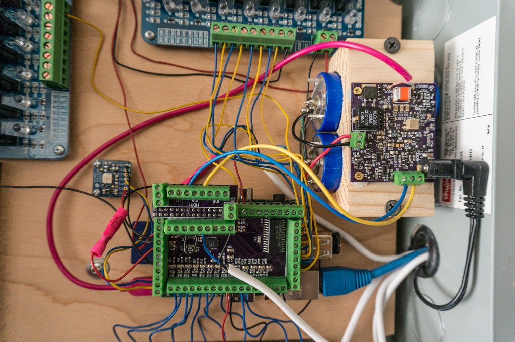
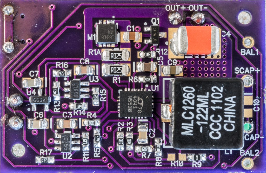
01/05/2019 at 06:22 • 0 commentsI received the LG4 PCBs last week. There was no point in assembling them since I did not have the PIC10F202 micro controllers, which arrived yesterday. I was able to program the PICs (with my new PICKit4 programmer) and populated the PCBs today. So far so good. On the bench, the circuit performs as expected; and initial testing with a Raspberry Pi2B and ZeroW are ongoing.
![]()
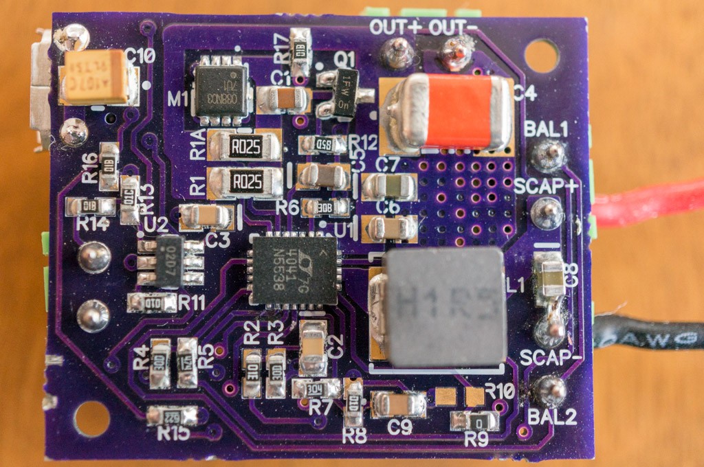
Yes, there is a solder bridge from SCAP- to C8, but it does no harm so I let it remain.
The relaxation oscillation problem from previous passes doesn't show up on this pass. I tried a couple different AC adapters without any issues. Reducing C2 to 22nF appears to have fixed it.
The PIC is performing its function as designed. I triggered the SHUTDN pin and timed out the oneshot and the off timer -- both were close to nominal design targets. There were no issues with the reapplication of power.
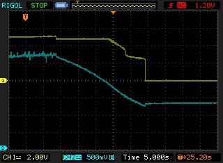
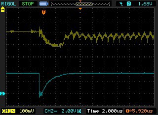
After verifying basic functionality, I attached a 4Ω load and a 100F supercap. I let the supercap charge to full (2.67V) and pulled the AC adapter out of the wall. Here's the resulting waveforms at the output and the supercap:
![]()
As expected, the 100F cap could not hold up the 1.2A load for very long -- not long enough to allow the older/slower Raspberry Pi variants to shutdown safely (but they also don't draw anywhere near this kind of current drain).
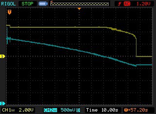
I swapped out the 100F with a 400F and repeated the test:
![]()
The 400F supercap provided 1.2A @ 4.81V for 80 seconds.
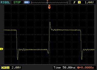
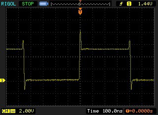
This is what the SW node looks like when charging:
![]()
and boosting to a 4Ω load:
![]()
There was no bandwidth limiting on my 100MHz scope. The switching waveforms don't have too much ringing.
Raspberry Pi Testing:
The Pi2B with the 400F supercap in the UPS is running without issues. I haven't seen any unexpected operation, but testing has been limited. I'm going to let the Pi2B/UPS combination run for a couple of days to make sure there are no spurious shutdowns or Pi hangups.
After that the ZeroW will get tested with the 100F supercap.
Almost finished...
-
A Better Way
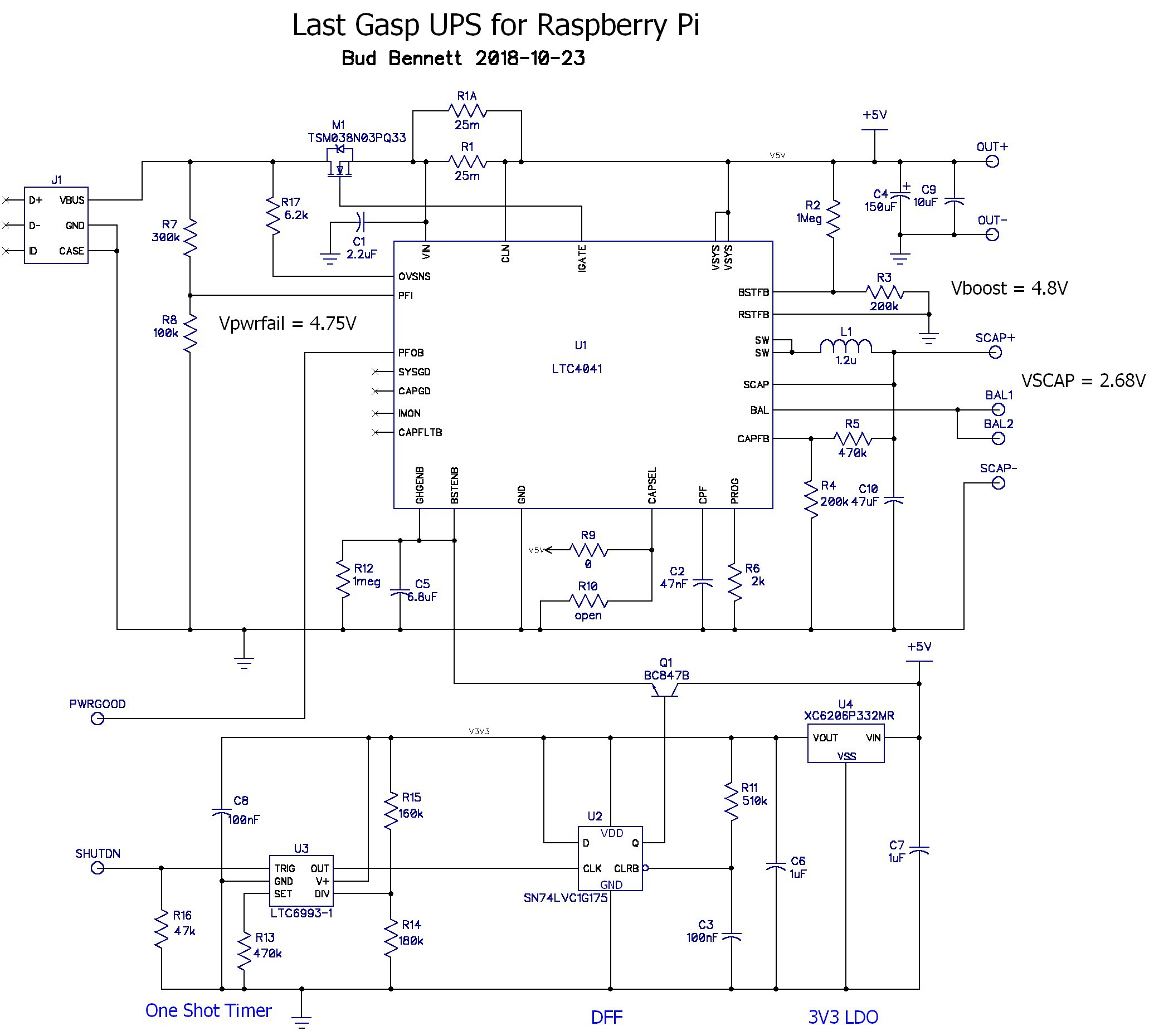
12/13/2018 at 04:13 • 0 commentsWhile I was waiting for the band-aid PCBs to arrive I got to thinking about a better approach for the timing circuits. The LTC6993-1 is cute, but at $3.50/each it doesn't seem like very good value. Plus the PCB space that the one-shot, DFF, and LDO consume doesn't justify the function. I set about to see if Microchip had any simple micro-controllers in a SOT23-6 package -- yes they do!
The PIC10F202 is a pretty bare bones µP -- just a watchdog timer, a clock/timer, and four I/O pins. A big plus is the 1% accurate 4MHz internal clock. It has a supply range of 2V-5.5V and uses TTL logic levels. Best of all, it's only $0.36 in low quantities -- and eliminates more than $4 of discrete components. I can also trade 3 SOT23 packages and a smattering of SMD components for a single SOT23-6 and two SMD passives. I'm sold.
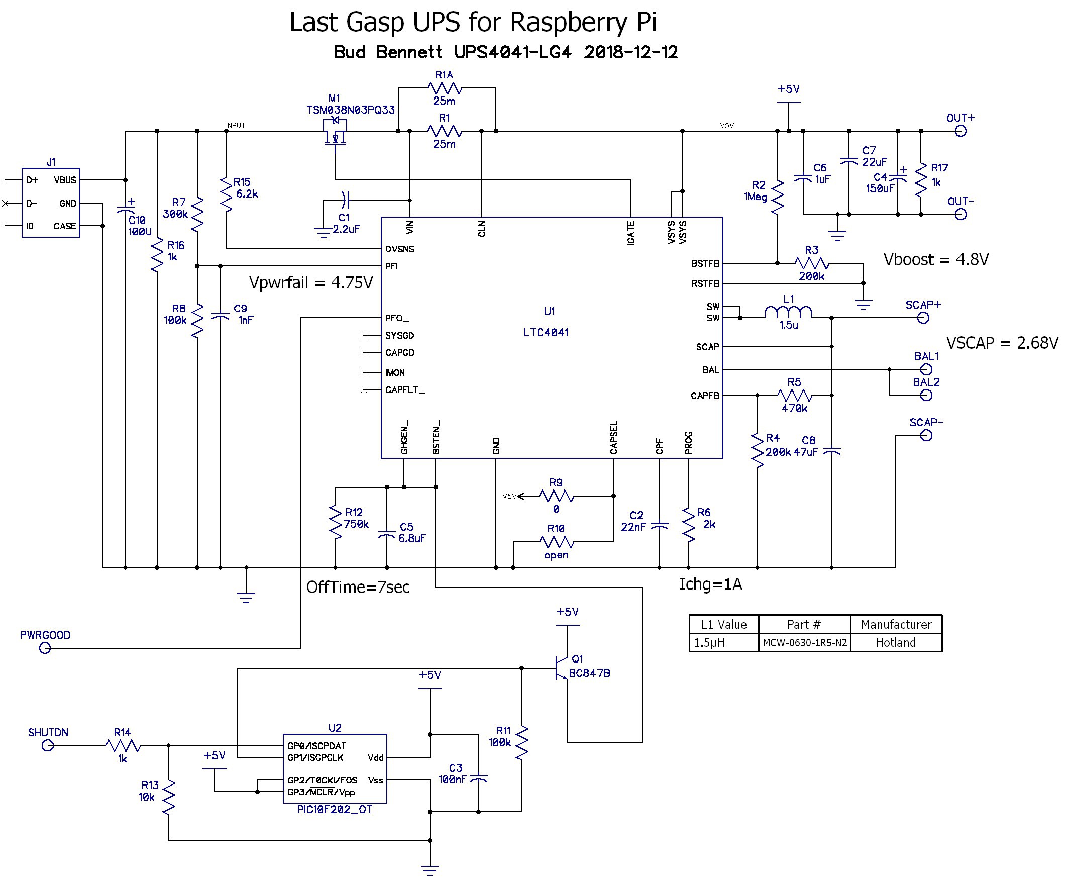
Here's the new improved schematic:
![]()
The small PIC simply replaces the one-shot, DFF and LDO. There is no noise filter on the SHUTDN input -- the PIC can provide noise filtering in the code.
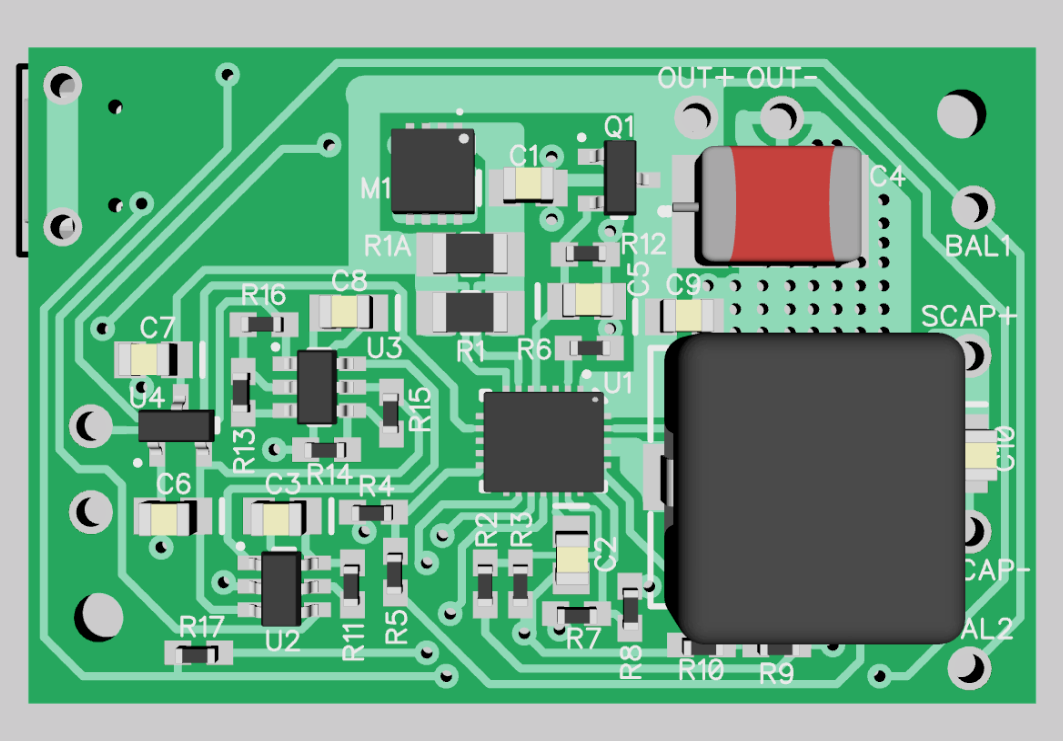
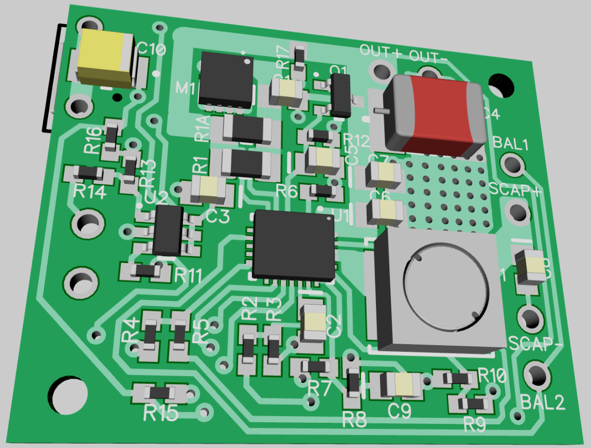
The layout is a lot smaller (1.05 inch x 1.275 inch):
![]()
The input output pads are arranged to accommodate 3.5mm terminal blocks so that all of the connections don't require soldering. The terminal blocks are mounted on the back side.
The balance leads are beefier (on the back side) and should support the 2.5A output load if you're going to employ 2 supercaps -- that was missing from earlier versions.
The option to use the larger 12x12 inductor is gone. This layout should work with most 6x6 or 7x7 inductors with adequate current/heat ratings. The inductor I'm using costs ~$0.09/each.
PCBs will be ordered soon.
-
UPS-4041-LG3 Results
12/13/2018 at 03:12 • 0 commentsI received PCBs yesterday and this afternoon I had a partially working board. I decided not to populate the LTC6993-1, the DFF and the 3.3 LDO. I was only interested in determining which band-aid fixed the problem in the simplest manner, and for that all I needed was a functional LTC4041. Refer to the schematic in the previous log for component references. A Raspberry Pi Zero W was used as a load in all of the testing.
R18, R19, and C12 were populated since I knew the impact of not having them in place from previous tests. R21 was a short and I left C13 unpopulated to see if it was needed or not. The value of C2 is 22nF, which decreased the TMIN-BACKUP time that the LTC4041 spends ignoring the power-fail comparator after it has tripped.
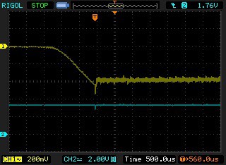
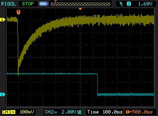
It turns out that this was all that was needed to fix the problem. I suspected that the relaxation oscillation was caused by the 500ms TMIN-BACKUP time being too long, which allowed the output voltage of the UPS to decay to zero during that interval. Decreasing TMIN-BACKUP to less than 50ms doesn't allow the output voltage to decay so far and can reach a point where it is above the UVLO threshold of the LTC4041 after one or two cycles. Here's a trace of input(CH2) and output(CH1) voltage during power-up.
![]()
You can see that the output voltage jumps a couple of volts before the PFI comparator switches off and forces the LTC4041 into backup mode -- but the voltage on the supercap is not high enough and the output voltage is not high enough either to allow the boost converter to run. So the output voltage falls back a bit until the TMIN-BACKUP time ends and the input switch is closed again -- this time the output voltage has climbed high enough to keep the booster enabled (or the PFI comparator doesn't trip because the input-output differential is not enough to drag the input voltage down below the PFI threshold.) In either case the output voltage is sustained and the UPS settles into normal mode with the input switch closed and the boost converter off.
I then populated C13 with a 220µF/6.3V tantalum, but it did not appear to make any difference in operation. I did not investigate the options with C14 and R21 -- I will remove those going forward. I've got enough confidence now to finalize the UPS design.
-
3rd Pass for the LTC4041 Version
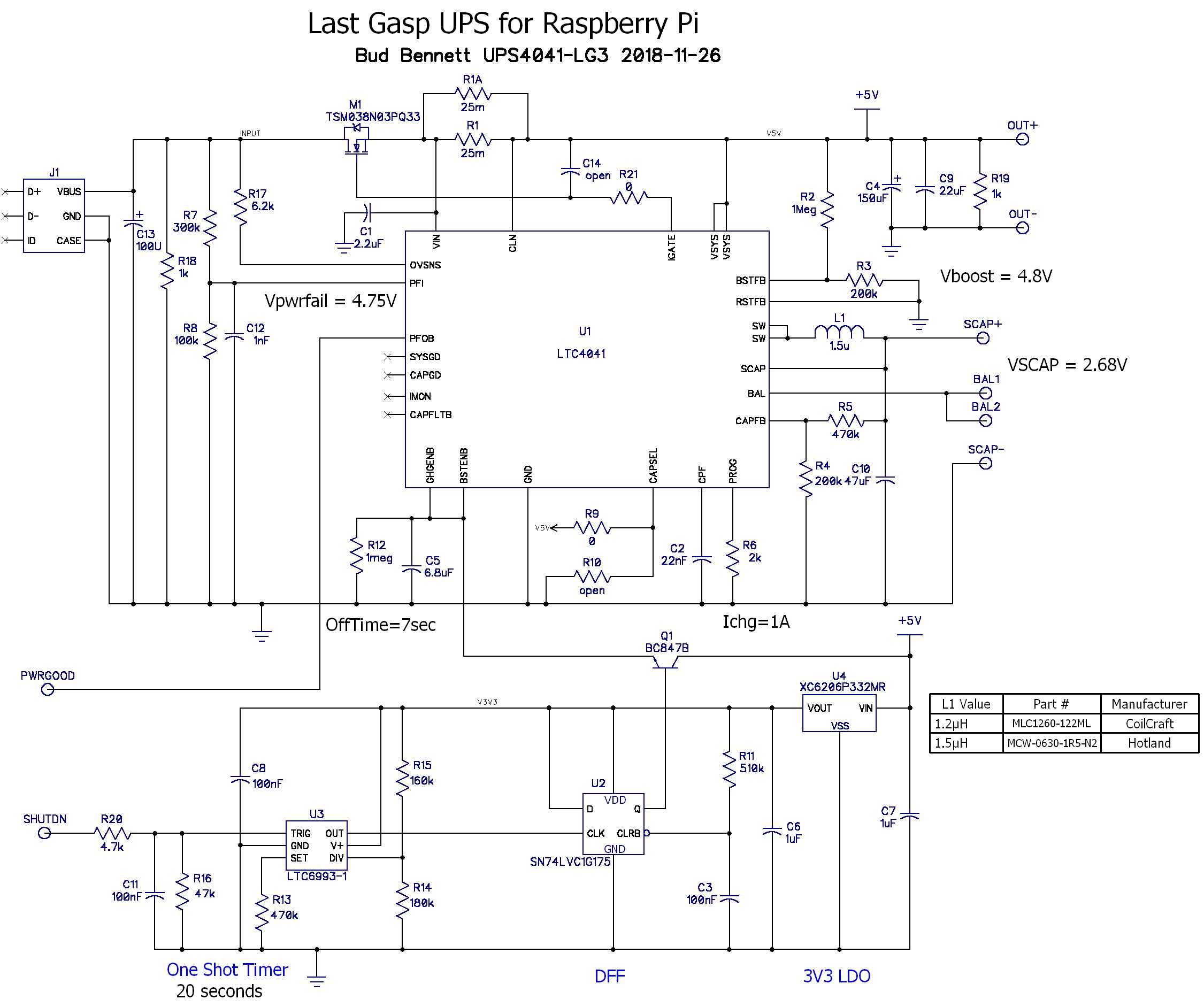
11/26/2018 at 17:11 • 0 comments![]() After an exchange of ideas with Analog Devices I have decided to apply a bunch of band-aids to try to fix the observed problems with the earlier versions. This design includes the RC filtering on the SHUTDN input, the RC filtering on the PFI pin, resistor loads at the input and output, and three modifications that deserve a bit more explanation.
After an exchange of ideas with Analog Devices I have decided to apply a bunch of band-aids to try to fix the observed problems with the earlier versions. This design includes the RC filtering on the SHUTDN input, the RC filtering on the PFI pin, resistor loads at the input and output, and three modifications that deserve a bit more explanation.Analog devices suggested the addition of an RC filter on the gate of M1, to reduce the inrush current when the input switch is turned on. The gate capacitance of M1 is already 2.5nF, so making R21 4MegΩ would slow down the switching time by about 4x. Increasing C14 to 7.5nF and setting R21 = 1MegΩ would have the same effect. I'm a bit leery of unintended consequences that may show up due to the slower turn-off time of M1, so this approach would probably be my last resort.
I added C13 at the input to help hold the input up when the input switch is closed. This may cause problems with the power fail comparator glitching after the input power is removed, but C13 can be removed if it worsens that issue. C13 is a tantalum, which should minimize voltage transients due to hot plugging the adapter.
Lastly, I reduced C2 from 220nF to 22nF. This reduces the minimum backup time from 500ms to 50ms. The reasoning behind this is to prevent prolonged relaxation oscillation by shortening the time between the input switch connections. If the output cap voltage is not allowed to fall completely back to zero then maybe after a few input cycles the oscillation will be broken. The success of this approach depends on the speed of recovery of the power fail comparator.
One more thing. I ordered a smaller inductor -- Hotland MCW-0630-1R5-N2. This new 1.5µH inductor is roughly 6.6x7x3 mm vs. 12x12x6 mm of the 1.2µH Coilcraft. The new induction is rated at 9A, which should be good enough for any intended load. The layout will accommodate either inductor.
New PCBs are on order.
-
More Problems with the LTC4041 version
11/19/2018 at 14:58 • 0 comments![]()
I installed the modified UPS board, and 100F supercap, into my heating system. It did not go well. The UPS would power the Pi and peripherals the first time that it was plugged in, but it would not apply power after a disconnection. I found two major issues that had to be fixed.
Oscillation
After unpacking the oscilloscope and looking at a few waveforms, I determined that the LTC4041 was put into an oscillation caused by its power fail comparator and the input switch. When the AC adapter is first powered up its output voltage ramps toward the final steady state voltage and it is forcing full current into the output. When the input voltage of the UPS reaches 4.75V the power fail comparator allows the input switch to connect the input to the output and there is a surge current which tends to glitch the input voltage downward. Since the AC adapter is still driving the input voltage upward it seems to overcome this glitch and the UPS powers the output just fine.
Things fall apart when the AC adapter is disconnected and then reconnected during the one-shot interval or the following power down interval. During the shutdown interval there is no current load on the AC adapter and its switch mode converter idles. When the LTC4041 comes out of the shutdown mode, the first thing it does is connect the input switch. The corresponding load spike that comes from connecting the 170µF load capacitance to the input creates a large downward glitch. (Sorry, I don't have pictures of any of this.) The glitch causes the power fail comparator to fire and try to switch to backup mode. The problem with this is that the voltage at SCAP is below 2.5V (by design) and the voltage at SYS is also below 2.5V so the backup converter is inhibited by the UVLO of the LTC4041. So nothing happens until the 500ms minimum backup time period ends and the entire cycle repeats, This is called a relaxation oscillation.
The end result is that the UPS is stuck in a loop that prevents it from connecting the input power to the output.
All AC Adapters Are Not The Same
My first attempt to get the UPS working used the AC adapter that was already working with the heating system. When I installed the UPS and plugged the AC adapter into the wall socket the UPS did not power the Pi. Apparently, that adapter could not respond adequately to the inrush current when the input switch closed so the UPS when into oscillation. Swapping out the adapter with a more responsive adapter solved that problem.
Solutions:
After grokking what was happening, my first thought was to place a huge capacitor at the input of the UPS. But that might cause the previous problem with the power fail comparator glitch to return.
My second solution was to examine the effect of filtering the power fail comparator input so that it would not respond to the short glitch when the input switch was connected. I reviewed my scope traces of a power failure event with a 4Ω load. The slope of the declining output voltage was fairly slow -- and the heating system current load was about half of the 4Ω load. I stacked an 0805 100pF ceramic cap on top of R8 -- creating a 10µs RC filter. Bench testing with the new filter showed improvement, but still occasional oscillation, so I increased the capacitance across R8 to 1nF. This stopped the oscillation, at least on the bench.
It also fixed the problem with the heating system. Now the UPS functions as designed, but I have a nagging feeling that this design needs to be tweaked for every application and so is not yet a robust, general purpose solution.
I'm thinking now that in addition to the power fail comparator filtering I should shorten the minimum backup time period, but haven't as yet worked through what effect that would have.
Updated Schematic:
This is the updated schematic with the RC filter at the PFI input.
![]()
I'm not going to replace the schematic in the project details section until I've exhausted the solution set. I've sent a query about all of this to Analog Devices. They haven't responded yet. In the meantime, I do have a working heating system.
-
New Python Code Running Under systemd
11/13/2018 at 19:35 • 0 commentsI'm no code bunny. Here's the current working code: powerfail.py
#!/usr/bin/env python
'''
This program monitors the status of the PWRGOOD signal from the UPS circuit.
PWRGOOD is normally high. If it goes low then the input power has failed.
This program senses when PWRGOOD falls and then samples it once/second. An
accumulator counts up by 1 if power is bad and counts down by 3 if power is good.
This accounts for the difference in supercap charge current vs. Zero-W load current.
If the accumulator exceeds 20 then it signals the UPS to disconnect the
power by asserting SHUTDOWN. This will still cause a shutdown condition even when
the power is cycling on and off. After it commits the hardware to shutdown it also
sends a shutdown command to the Linux system. The UPS will hold power up for 20 seconds
after it receives the SHUTDOWN signal, which allows the Pi to enter a shutdown state
prior to power removal.
'''
import RPi.GPIO as GPIO
import os, time, sys
import logging
import logging.handlers
#import traceback

# global variables
COUNT_UP = 1
COUNT_DOWN = 3 # this relates to the ratio of charger current divided by load current
COUNT_MAX = 20 * COUNT_UP # how many seconds of power loss before the Pi shuts down
# set the GPIO pin assignments
PWRGOOD = 23
SHUTDOWN = 24

#--logger definitions
logger = logging.getLogger(__name__)
logger.setLevel(logging.INFO)  # Could be e.g. "TRACE", "ERROR", "" or "WARNING"
handler = logging.handlers.RotatingFileHandler("/var/log/bud_logs/ups_mon.log", maxBytes=1000, backupCount=4) # save 4 logs
formatter = logging.Formatter('%(asctime)s %(levelname)-8s %(message)s')
handler.setFormatter(formatter)
logger.addHandler(handler)

class MyLogger():
    '''
    A class that can be used to capture stdout and sterr to put it in the log

    '''
    def __init__(self, level, logger):
            '''Needs a logger and a logger level.'''
            self.logger = logger
            self.level = level

    def write(self, message):
        # Only log if there is a message (not just a new line)
        if message.rstrip() != "":
                self.logger.log(self.level, message.rstrip())

    def flush(self):
        pass  # do nothing -- just to handle the attribute for now


# configure the GPIO ports:
GPIO.setmode(GPIO.BCM)
# PWRGOOD is an input with weak pullup
GPIO.setup(PWRGOOD, GPIO.IN, pull_up_down = GPIO.PUD_UP)

def powerfail_detect(count_max, count_up, count_down):
    # if the count exceeds 20 the system will shutdown.
    count = 0
    pwr_flip = False
    while (count < count_max):
        time.sleep(1)
        if (GPIO.input(PWRGOOD)):
            if (pwr_flip):
                logger.info("Power is good")
            count -= count_down
            pwr_flip = False
            if (count <= 0):
                logger.info("Returning to normal status")
                return
        else:
            if (not pwr_flip):
                logger.info("Power has failed")
            count += count_up
            pwr_flip = True
    logger.info("powerfail iminent...shutting down the Pi!\n")

    GPIO.setup(SHUTDOWN,GPIO.OUT)
    GPIO.output(SHUTDOWN,0)
    time.sleep(0.1)
    GPIO.output(SHUTDOWN,1)
    time.sleep(0.1)

    os.system("sudo shutdown -h now")
    GPIO.cleanup()
    return

# If this script is installed as a Daemon, set this flag to True:
DAEMON = True # when run as daemon, pipe all console information to the log file
# --Replace stdout and stderr with logging to file so we can run it as a daemon
# and still see what is going on
if DAEMON :
    sys.stdout = MyLogger(logging.INFO, logger)
    sys.stderr = MyLogger(logging.ERROR, logger)

try:
    logger.info("Enabled")
    while True:
        time.sleep(1)
        if (not GPIO.input(PWRGOOD)):
            powerfail_detect(count_max=COUNT_MAX, count_up=COUNT_UP, count_down=COUNT_DOWN)

except:
    GPIO.cleanup()  # clean up GPIO on CTRL+C exit
Note that the log file is located in /var/log/bud_logs/ups_mon.log. It will rotate the log after 1000bytes and keep the latest four logs. You can change all of that by altering the handler params.
The above script is located in /home/pi/programs/ and runs as a service using systemd on either the Jessie or Stretch version of Raspbian. You can locate it anywhere as long as the service knows the path. The powerfail.service file below is located in /lib/systemd/system/
[Unit]
Description=Powerfail Service
Before=multi-user.target

[Service]
Type=idle
ExecStart=/usr/bin/python -u /home/pi/programs/powerfail.py
Restart=on-failure
RestartSec=10
TimeoutSec=10

[Install]
WantedBy=multi-user.target
Note that the ExecStart line must have full pathnames to both python and the program. In order to activate this service you need to type the following in a terminal shell:
sudo systemctl daemon-reload
sudo systemctl enable powerfail
sudo systemctl start powerfail
Now the service is running and will automatically run the powerfail.py code upon boot. To check the status of the service simply type:
systemctl status powerfail
Here's an example of the log file output:
2018-11-13 11:38:01,870 INFO     powerfail iminent...shutting down the Pi!

2018-11-13 11:38:30,161 INFO     Enabled
2018-11-13 11:41:25,759 INFO     Power has failed
2018-11-13 11:41:29,767 INFO     Power is good
2018-11-13 11:41:30,772 INFO     Returning to normal status
I will provide a copy of powerfail.py in the files section of this project.
-
UPS4041-LG2 Results
11/12/2018 at 01:13 • 0 commentsI received the second pass PCBs on 11/7/2018. I was busy, so I did not populate one of the boards until 11/9. I had second (third?) thoughts about a couple of items so I increased C9 from 10µF to 22µF to reduce the impedance at the output and hopefully reduce the ripple voltage at the output; and I increased C2 to 220nF to increase the minimum backup time to 500ms, having some concerns about how the power-fail comparator was going to function with the AC adapter. Here's the newly populated board:
![]()
My initial testing was limited to a power supply input and a resistive load -- I found out quickly that bench testing doesn't equate to the real thing. But on the bench the UPS appeared to be fully functional.
Measured Bench Parameters:
(All of these parameters measured with single 400F supercap. )
Full Charge VSCAP voltage = 2.67V (design target = 2.68V)
Charge Current = 1.075A (measured assuming 400F ±10% supercap: time to charge from 2.5V to 2.6V = 37.2 sec.) Design target = 1A.
Backup Voltage = 4.77V with 4Ω load resistor (design target = 4.8V)
Input Power Fail threshold = 4.75V (same as design target).
Power Off time out period, after 20 second one-shot interval = 8.3 second (design target = 5-10 sec.)
Anecdotal Data:
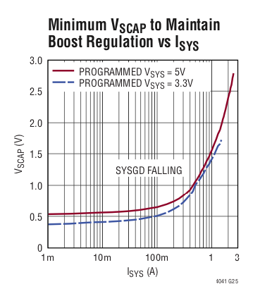
With a 2Ω load the output voltage during backup did not reach 4.8V. The output voltage dropped from 4.95V to 4.64V immediately after the input power was cut and descended below 4.5V within a few seconds. Clearly this circuit was not going to provide a 2.5A load during backup with a single supercap. The LTC4041 data sheet confirms it with this plot:
![]()
I wanted to determine if the circuit could manage two sequential power failure events. With a 4Ω load resistor the circuit maintained 4.77V at the output after 2 sequential power failures (30 second duration with a 4Ω load). The final voltage at SCAP was 2.19V.
Bench Testing Waveforms:
Here's a trace of the output voltage and PWRGOOD signal when the power was cut to the adapter (RL = 4Ω):
![]()
The initial voltage was 5.15V -- so the output voltage dropped to about 4.6V before the boost converter took action. A short glitch below the specified operating voltage of the Raspberry Pi doesn't appear to be a problem (in my experience).
In the above waveform there doesn't appear to be any indication of a power failure on the PWRGOOD signal (channel #2). If we expand the timeline it becomes clearer:
![]()
The PWRGOOD signal drops for only a few µs because the backup system takes over and removes the load from the input. Once the power-fail comparator has tripped the LTC4041 keeps the system in backup mode for a time period set by the capacitor on the CPF pin, C2. With C2 = 220nF this period is approximately 500ms. This is to allow the input voltage to relax to a low level and avoid potential oscillations. After this initial short glitch the PWRGOOD signal doesn't fall again until much later:
![]()
As it turns out 500ms wasn't long enough. When the AC power fails the AC adapter stops operating with the effect that the input just becomes a high impedance with a large capacitor. Without any load the input capacitor takes a long time to discharge and so the power-fail comparator can be fooled into thinking that there is still a power source at the input. The fix is to place a resistor at the input to discharge the input capacitance to a level below the power-fail comparator trip point before the 500ms minimum backup period expires. A 1kΩ resistor does the trick. I should have known to do this since the first discrete version of this UPS included this resistor -- but that circuit had the benefit of simulation using LTSpice.
Real World Testing:
Not wanting to destroy my more expensive Raspberry Pi units I chose a Raspberry Pi Zero-W for testing. Using a 400F supercap for the Zero-W is overkill. I had to wait 250 seconds for the supercap voltage to drop below 2.5V while in backup mode. This equates to a current draw by the Zero-W of only 300mA.
I was gratified when the Zero-W powered up and booted. But when I disconnected the AC adapter the UPS provided power but did not indicate a power failure on PWRGOOD. It took a while before I figured out that the load at the input was too light and I added the necessary 1k resistor to the input terminals. After that, the UPS provided backup power, the PWRGOOD indicator worked, and the Zero-W did not show any signs of distress as I connected and disconnected the AC adapter.
My next test was to manually shutdown the Zero-W and then manually assert the SHUTDN signal to the UPS. When I reconnected the AC adapter the Zero-W did not boot. I measured 1.2V at the UPS output. It was stuck in some weird mode and did not recover when input power was applied. The problem turned out to be too light of a load at the output. I noticed that the output voltage would drop relatively quickly to below 2V, but then just drift downward for a very long time. I think that this was interfering with the POR circuitry on the one-shot and DFF. I added another 1k resistor at the UPS output and this problem went away. The UPS would now properly time out the backup interval, shutdown the output, and properly re-apply the power when the AC adapter was reconnected.
At this point I modified the powerfail.py program and launched it. There were a few glitches with respect to initializing the GPIO properly but after that was fixed it appeared to run properly...for a while. When I turned on my soldering iron, situated nearby, the Zero-W crashed about 20 seconds later. There was something causing the SHUTDN input to trigger the one-shot when the solder iron was turned on. My first thought was to use shielded cable to connect the SHUTDN signal to the UPS, but eventually settled upon an R-C filter to fix whatever was causing the one-shot to trigger.
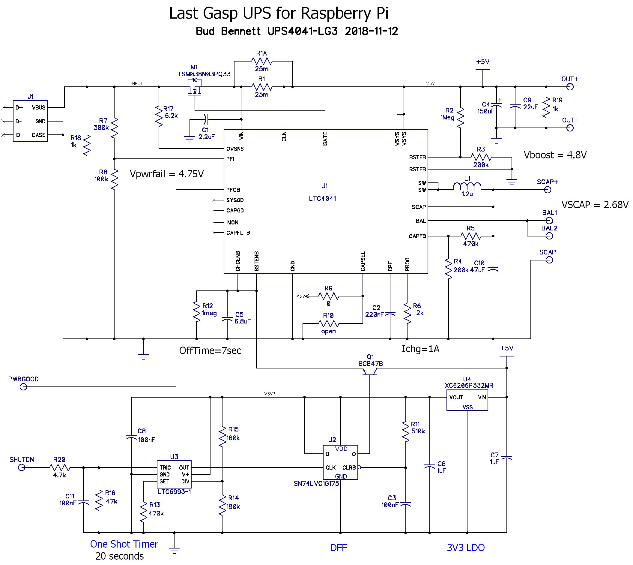
Now the UPS is functioning properly and not susceptible to any outside interference. Here's the final schematic:
![]() The newly added components are R18, R19, R20 and C11. I added the new components to the existing PCB: R18 was easy -- just scratched some of the solder mask away and soldered the new 0603 resistor in place, R19 was a through-hole 1/4W carbon resistor between the OUT+ and OUT- terminals, C11 is an 0805 cap wedged between the SHUTDN terminal and GND at C7. I decided to just put R20 in series with the wire from the Raspberry Pi to the SHUTDN terminal block. Needless to say the board is not as pretty now.
The newly added components are R18, R19, R20 and C11. I added the new components to the existing PCB: R18 was easy -- just scratched some of the solder mask away and soldered the new 0603 resistor in place, R19 was a through-hole 1/4W carbon resistor between the OUT+ and OUT- terminals, C11 is an 0805 cap wedged between the SHUTDN terminal and GND at C7. I decided to just put R20 in series with the wire from the Raspberry Pi to the SHUTDN terminal block. Needless to say the board is not as pretty now.Ready for Deployment:
My target application uses an original Raspberry Pi Model B, which doesn't consume much more current than the Zero-W. It doesn't need a 400F supercap and I don't need it to ride through a power disruption. So I changed out the 400F for a 100F supercap that I got from eBay, and connected the UPS to the Pi Model B.
The 100F supercap fully charges from zero volts in less than 5 minutes.
I changed the parameters of the powerfail.py program to allow the power to be absent for 10 seconds before initiating the shutdown procedure. This gives a total time of 30 seconds for the UPS to provide power to the Pi. I monitored the SCAP voltage while I disconnected the AC adapter. The ESR of this 100F supercap is a LOT higher than the 400F that I got from Digikey since the voltage on SCAP dropped about 50mV immediately. The voltage on SCAP after the UPS turned off the power to the Pi was 2.38V. So far so good.
I then plugged the AC adapter in, waited a few seconds, and unplugged it to see how the UPS would ride through a glitching AC source (we get that quite a bit out here in rural Colorado). The powerfail service detected the loss of power as soon as the service started and then safely shutdown the Pi before the Xwindow GUI loaded. The voltage on SCAP after the second power failure was 1.9V.
Summary:
It's ready for prime time. I just need to clean up the code in powerfail.py and install the UPS into the heating control system running in the garage. I'll post the new code when it's finished.
I probably won't build another PCB with the updated components, but I did modify the PCB layout with the changes. I'll post the latest schematic, BOM and Gerber files for the PCB layout to the files section of this project when I get the time.
-
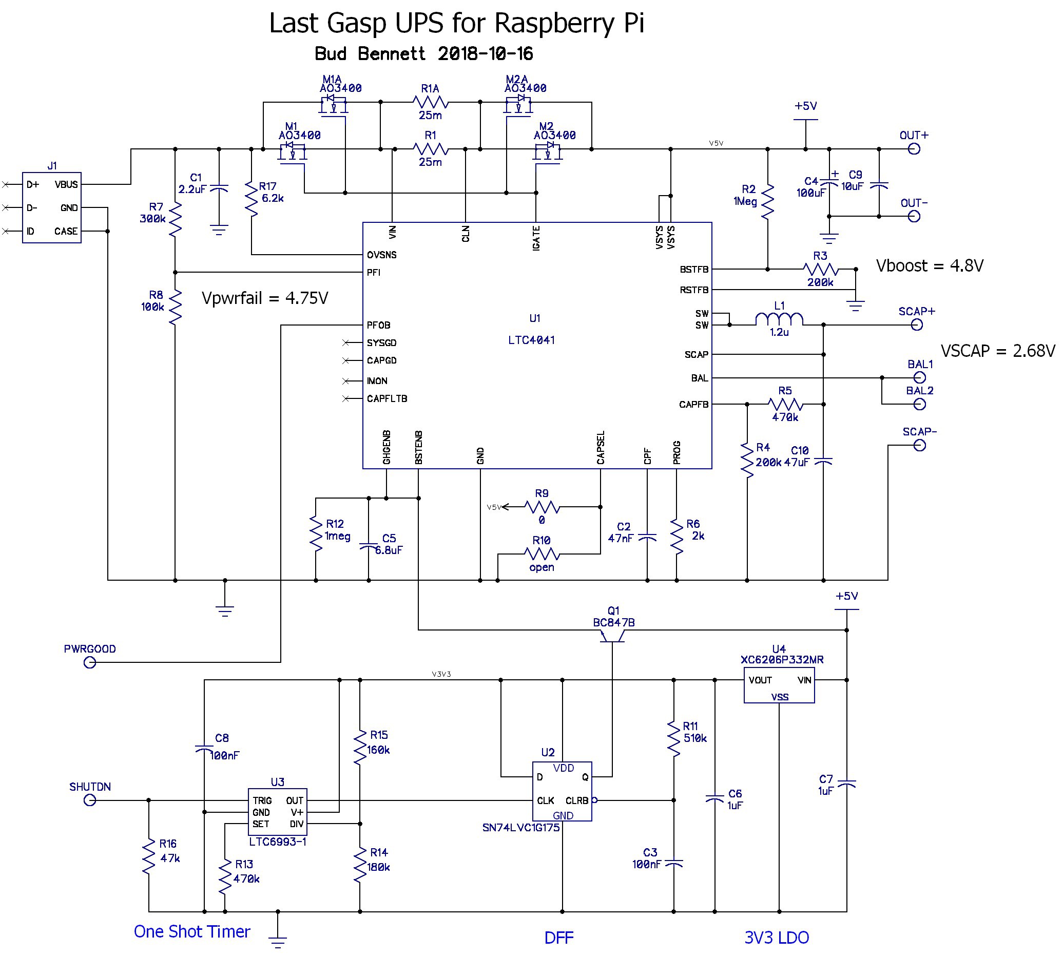
Changes to the LTC4041 approach
10/23/2018 at 21:06 • 0 commentsAs usually happens, I was thinking about some aspect of this design when I had a blinding glimpse of the obvious. It is going to cause me to toss the first version of the LTC4041 design without even populating the PCBs.
Simplifying the input switches:
The first version of the design had two pairs of FET switches to disconnect the input source. I got to thinking that I did not need to actually disconnect it since it just presents a high resistance load when the AC power fails. I could use a single FET switch if I connected the drain to the input and the source to the VIN pin of the LTC4041. This reverses the body diode of the FET so that the input won't hold up the output voltage to the load if the input power returns. But in this configuration the body diode of the input FET won't let the input voltage fall more than a diode drop below the output voltage. In this application this is not a problem -- as long as the input voltage is less than the 4.75V power fail comparator threshold of the LTC4041.
Here's the version 2 schematic:
![]()
M1 is a 30V, 4mΩ RDSon, logic level FET that I used on one of the magnetic switch projects. The package is a 3.3x3.3mm DFL powerPak, which has become pretty standard for these types of devices. I also upgraded C4 to a 150µF low-ESR tantalum (Vishay 594D157X9010D2T -- 10V, D-case, 80mΩ ESR). There are a few of these in my inventory and I haven't been able to use it because of its size, but in this case it fit.
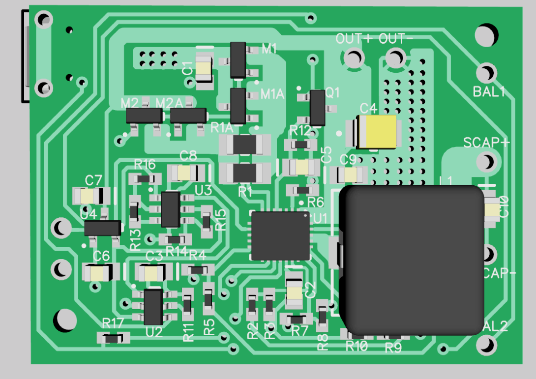
The Layout is Smaller:
![]()
1.05"x1.613" Almost 15% smaller than the first version. I don't particularly like the way that the output and input traces spiral around each other, but that was forced by the pinout of the LTC4041.
So now I will order another set of PCBs. Three of these boards should cost about $8.50 from OSH Park. It will take 3-4 weeks to get them.
-
A possible upgrade -- the LTC4041
10/12/2018 at 23:04 • 0 commentsI received a junk email from Analog Devices (they absorbed Linear Technology a short while ago) with a teaser about a new super capacitor backup IC -- the LTC4041 -- claiming to provide a 2.5A backup booster and buck-mode super capacitor charger for a single or dual super capacitor stack. I was intrigued. After downloading the data sheet, and understanding it somewhat, I decided to try to implement the Last Gasp UPS using the LTC4041 as the main ingredient.
I spent a couple of days ruminating about how to make it work as a Last Gasp UPS for the Raspberry Pi. The schematic below is my first attempt. If it works out, I'll build a couple PCB prototype boards to test the concept.
![]()
The circuit above (see this project details for the latest schematic) reflects what I have in my current inventory. I'm using AO3400 NCH FETs as the input switches because they are already in my inventory and really cheap at about $0.03/each. R1 is split into two components because I don't have a 12.5mΩ power sense resistor, but I do have 25mΩ 1206 sense resistors. The inductor, L1, is the same as what I bought before -- a CoilCraft MLC1260-122ML -- which is bigger than what Analog Devices recommends, but I can't get it because Digikey doesn't stock it.
Circuit Operation:
Normally, the input power is connected to the load by the two inputs switches, M1-M2. The super capacitor backup source is charged to either 2.7V (single SCAP) or 5V( dual SCAPs). The final voltage on the supercap(s) is determined by R4-R5. The CAPSEL pin selects programs the LTC4041 for either one or two supercaps. If there are two supercaps the charger automatically balances the voltage across them. The charge current is set to 1A by R6. If the sum of the charger and load currents exceeds 2A, set by R1, then the charge current is reduced until the sum of load plus charge currents is 2A. This is to avoid overloading the input power source.
The LTC4041 detects when the input voltage drops below 4.75V, set by R7-R8, and then disconnects the input switches (M1-M2) from the load. It also activates the boost converter to provide 4.8V to the load, using the stored energy on the super capacitor(s). The output voltage is set by R2-R3. If the input power becomes available again the LTC4041 automatically disables the booster and reconnects the load to the input. Without any intervention the boost converter would try to keep the load voltage at the programmed setting until the voltage on the super capacitors(s) was too low, then eventually drop the load voltage as the super capacitor backup voltage decreased to a point where it couldn't sustain the output power.
The added circuitry communicates the loss of power to the Raspberry Pi (the load), and then initiates a shutdown sequence after the Raspberry Pi indicates that it is committed to a shutdown sequence by asserting the SHUTDN input. The SHUTDN input triggers a oneshot timer that keeps power applied to the load for about 15-20 seconds (while the RPI shuts down its running processes). At the end of the one shot interval the DFF is clocked to a high state, which pulls the BSTENB and CHGENB pins to about 2.8V via the emitter of Q1. The LTC4041 goes into a shutdown state at this point and disconnects the input switches, M1-M2, and disables the booster letting the output voltage fall to zero. The voltage on the BSTENB and CHGENB pins floats slowly back down with a time-constant determined by R12-C5. When the voltage drops below 1.4V the LTC4041 is re-enabled to resume normal operation. If the voltage at SCAP is below 2.5V and the input voltage is low then the LTC4041 remains in a shutdown state until the input voltage rises above 4.75V.
When input power becomes available again the load is reconnected and the Raspberry Pi reboots. Then the cycle repeats.
A few things to worry about:
- This project is billed as "A single supercapacitor ...", but this chip has all of the equipage to handle one or two super capacitors. So why not? I left options to use 2 supercaps in the circuit. If 2 supercaps are used, then make sure that the voltage on the SCAP pin has discharged below 2.5V when the one-shot timer expires or else the booster could be re-enabled and reboot the Raspberry Pi even if there is no input power applied. Whether that is a bad thing or not is up to you.
- There is a race condition when the LTC4041 is disabled at the end of the one-shot interval. Q1 is attempting to pull CHGENB and BSTENB to 2.8V while the booster is disabled and the output voltage is going toward zero volts. I don't think that this will be much of an issue because the Raspberry Pi is not much of a load at this point and the output voltage should fall relatively slowly. But you never know for certain.
- I'm a bit worried about the state of the one-shot and the DFF upon application of power (the POR condition). The LTC6993-1 is supposed to remain in a reset condition for 8ms or so and not respond to TRIG inputs. The DFF is held in a reset state by R11-C3 for about 50ms. Hopefully these circuits will ride through the POR condition predictably.
The Layout:
I got in touch with the designer of the LTC4041 regarding some areas of operation that needed clarification. His answers reassured me that I was on the right track so I spent some time (& money) making a PCB for the design.
![]()
![]()
The PCB is 1.188in x 1.625in. It will be fabbed by OSH Park in 2-layer 2 oz. copper and I'll get them around the first week in November. I'm not really happy with the PCB layout -- the NE and NW corners are pretty much empty, so it's not very efficient use of space. But it's 33% smaller than my other circuit so I can't complain too much.
I'll check in again after I get the PDBs and can test it out.
-
Version 1 Installed and Working
06/26/2017 at 19:36 • 0 commentsThe following pertains to the first version of the circuit.
The heating system was in use until June 1st, so I did not want to take the chance of screwing something up and then trying to fix it in panic mode. I decided that I did not really need another super capacitor laying around so I rewired the two 350F super caps used by the previous UPS from series to parallel and connected them to the new UPS. This also made the mechanical changes easier (i.e. no mechanical changes). I had to discharge both super caps completely before messing with them. Here's the new UPS installed into the enclosure for the heating system controller:
![]()
The previous UPS was wired directly into my data acquisition "Hat". This UPS connects via the normal microUSB for power. Note the bright pink cable that I got from the dollar store...for a dollar!
I had to change the GPIO assignments for the powerfail.py code since GPIO24 was already in use. I let the supercapacitors charge to full voltage overnight and then pulled the plug on the wall wart. It went through the shutdown procedure like clockwork and shutoff the power to the Pi. When I plugged the wall wart back in power was reapplied after 5 seconds. Mission accomplished.
Single SuperCapacitor UPS for Raspberry Pi
A last gasp Uninterruptible Power Supply for any Raspberry Pi computer.

 After an exchange of ideas with Analog Devices I have decided to apply a bunch of band-aids to try to fix the observed problems with the earlier versions. This design includes the RC filtering on the SHUTDN input, the RC filtering on the PFI pin, resistor loads at the input and output, and three modifications that deserve a bit more explanation.

 The newly added components are R18, R19, R20 and C11. I added the new components to the existing PCB: R18 was easy -- just scratched some of the solder mask away and soldered the new 0603 resistor in place, R19 was a through-hole 1/4W carbon resistor between the OUT+ and OUT- terminals, C11 is an 0805 cap wedged between the SHUTDN terminal and GND at C7. I decided to just put R20 in series with the wire from the Raspberry Pi to the SHUTDN terminal block. Needless to say the board is not as pretty now.