This could almost be a log for #The Rise and Fall of Pulses but we're operating in the microsecond range, which is a relatively geological timescale compared to those pulses!
There's a certain amount of curiosity that drives this project along. The pulse generation is a point in case. As you may have noticed, I've recently been playing with the new-ish ATtiny402, a part that shares many of its peripheral and register settings with two families of parts the ATtiny 0 series and ATtiny 1 series. In theory, there's a huge amount of flexibility for an engineer to switch quickly between parts because the code will be so portable. In reality, the datasheets have suffered from what appears to be a relatively high degree of copy and paste, or at least the assumption of commonality hasn't been tested. This can mean that discovering how a peripheral needs to be set up for parts like this that don't have many readily published examples, can be a "voyage of discovery" to put it mildly.
#Yapolamp needs pulses (although as I have pondered @Sander van de Bor's #ATtiny Super Capacitor Spider which drives its LEDs purely with PWM to produce a fade effect, I wonder if protection against MOSFET failing ON could allow this to be a contender for the #Yapolamp . Anyway, I'm deep into the inductor driver rabbit hole at the moment and the delights of the ATtiny402 (not its datasheet, but the IC itself!) are more than adequately holding my attention.
You may recall that I used TCB0 on the ATtiny402 to generate a nice, duration controllable pulse on the Waveform Output (WO) pin, PA6. This was lovely because using another neat trick of the ATtiny402, I can measure the continually decreasing supply voltage from the supercapacitor to the circuit and automatically adjust the pulse to assure we were achieving the same sawtooth current profile throughout the full voltage operating range, which is over 3V. By controlling the current, I am happy that this is a proxy for brightness, so I don't need to "test" that we are maintaining the same light level across the range of supply voltage. I also chose this current profile because it represents the most efficient conversion of electrons to photons, according to my shonky tests.
But all of this was using delay() and as I'm playing with the 402, why don't we see if we can generate the pause, after the pulse, during which we wait for the inductor to discharge through the LEDs, in a more convoluted way? Great, glad you're onboard with that. Options to do this with the older ATtinies would have included timers. Here's the timer option set for the 402:

We have already committed TCB0 to doing duty on the single shot pulse generator, so that's off limits. We do have TCA0 on the ATtiny402, although this is reserved in the megaTinyCore for all the Arduino timing stuff, exactly like millis(), delay(), micros() and microSeconds(). So best not to mess with that for now (although you can mess with what you like if you can live with the consequences). The last one, the RTC, is a nice little thing not really with an equivalent in the older ATtinies. It runs from the 32kHz oscillator though, so the fastest period it has is 1/32000 or ~ 30us. My sawtooth discharge at 12-14mA takes around 10us, so we'd be extending total duty from between 30-60% (for 1.8v - 4.8V respectively) down to 25-50%. Maybe not drastic but I think we can do better, and there's no guarantee that we can actually do anything within a single RTC clock cycle. In fact, as far as I can tell from the dubious datasheet, the shortest Periodic Interrupt Timer is 4 cycles, plus whatever time it takes you to service that ISR, and the fastest you could do an event driven approach is 64 cycles. Not worth investing in for this use but definitely worth returning to, perhaps as part of #ATtiny 0 Series programming on the cheap.
Events, dear boy
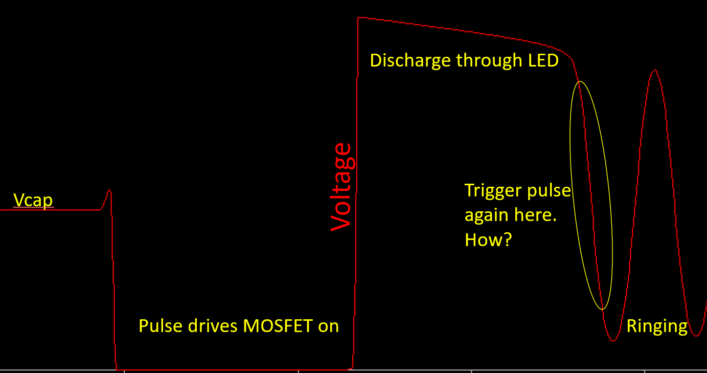
The new kid on the 0 and 1 series block is the core-independent peripherals. Core independent means that they don't need the CPU to service an ISR, some of them don't even need to wait for the clock ticks to trigger and many of them will work with low power modes. The Events System is like the glue that ties all your peripherals together and I wanted to try using this to optimise the driver MOSFET pulse, beginning as soon as the current had stopped discharging from the inductor through the LEDs. In voltage terms, we can see this drop in the voltage at the connection between the inductor and MOSFET.

I managed to use the Event System to glue the logic of a falling edge from the inductor attached to an input pin on the ATtiny402 and set that to generate the pulse using TCB0 in single shot mode. However, real life often turns out differently than (a badly set up) SPICE simulation. The lowest point on the inductor falling edge never got low enough to trigger a logic low on my GPIO. This meant the whole closed-loop feedback died after the first pulse. At least I could see this on my oscilloscope - it really is an amazing tool. So then I tried a voltage divider and VICTORY! There was light...
However, my joy was short lived, because when I tested this arrangement across the 1.8V - 4.8V working range of Yapolamp 1.1, above 4V this arrangement didn't work because the voltage dip didn't drop low enough. If I adjusted the voltage divider ratios, the feedback seemed to fail at one or other end of the operating voltage range.
At this point, I have found another way around. I know that the peak voltage of my inductor input into the ATtiny402 is Vcapacitor + Vforward for my LED. This means that if I "knock" Vforward off the top of the pin input, it will see more normal ranges of 0V - Vcapacitor. So far, a 7th LED is acting as my voltage drop diode in this way, with a V - 4.7k - 10k - GND voltage divider in series. This sustains the feedback loop at all operating voltages. The disadvantage is that now I have a small current across the voltage-dropper LED, so I will be looking into how to turn this off when we get to some power saving techniques for the "always on" or "find me in the dark when I'm turned off" mode.
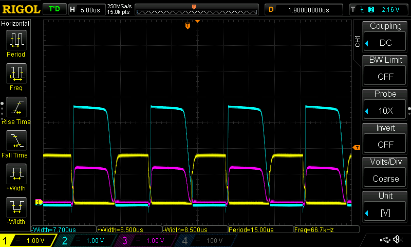
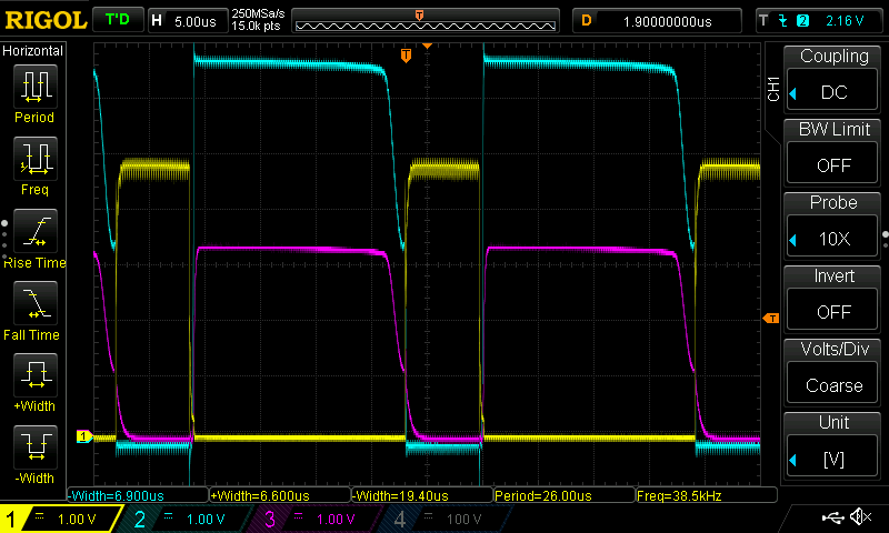
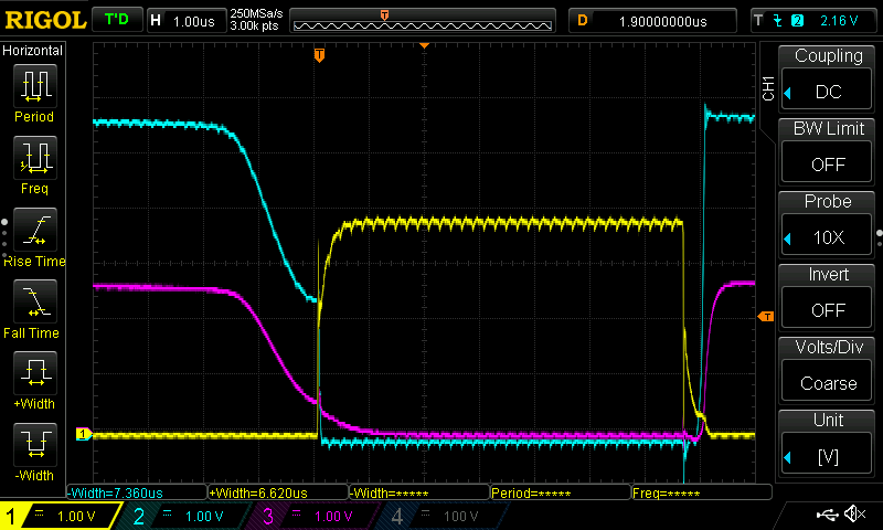
In the following traces, yellow represents the MOSFET gate-driving pin on the ATtiny402, so high means the MOSFET is ON, blue represents the "full" voltage at the inductor and going into the LEDs, and magenta represents the "dropped" voltage going into the ATtiny402's input, from which the asynchronous pulse is generated using the Event System.
Just to clarify, the following pulse regime has NO code running in the loop() section. There is ONLY one timer and the Event System dynamically adjusting to the varying discharge durations. There is a noticeable change in brightness because the discharge durations vary with the inductor charge voltage (Vcapacitor), but we already have a solution for varying driver pulse duration automatically, which will drop nicely into loop() later!
1.8V

4.8V

Close up

I have suffered some painful grappling with the datasheet of this new-ish chip, thanks in part to the ambiguity and perhaps errors in the datasheet but also due to me being unfamiliar with reading microcontroller datasheets. I have certainly learned a lot and will see if I can maintain this trend for CPU-independent performance. It may come in handy when we need #Yapolamp to go to go low power...
 Simon Merrett
Discussions
Become a Hackaday.io Member
Create an account to leave a comment. Already have an account? Log In.
@Alan Green, this afternoon I've been looking at the AC event to replace the digital logic event (with voltage dropper+divider) as the pulse trigger but I think two factors are conspiring to prevent this with the 402. Firstly, we are unable to use VDD as a VREF setting in the 0 series. This means we need to connect VDD to AC_NEG or AC_POS pins. And we need to connect Vinductor to the other one. Unfortunately, AC_NEG pin on the 402 is the same as TCB0 Waveform Out, which is generating our MOSFET-driving pulse.
The promising news is that the 204/404 have separated the TCB0 WO pin from both the AC_NEG/POS pins, so this could work perhaps with one of those. I'm probably going to get a version done with the dropped digital feedback on the 402 and may look at the 404 for a future version.
Are you sure? yes | no
I'm all for using the 404. On Digikey, it's the same price as the 204, but has twice the flash, a whole quarter KB of memory, many I/O pins and all in an easy to solder SOIC package.
For the AC, it would be possible to compare to the voltage reference at 1.1V or 0.5V, and use that to drive the MOSFET on. Yapolamp currently triggers on a digital input high-low transition, meaning it senses the drop somewhere between 0.7 Vdd and 0.3 Vdd which is 1.26V to 0.54V at Vdd=1.8V. You would still get the certainty of a transition point that didn't vary with Vcap, though I have no idea whether it is worth the additional complexity.
Are you sure? yes | no
I'm avoiding the fixed VREFs because at Vcap = 4.8V the numbers look rather different. We'd then be into the case of setting AC VREF based on the measured Vcap, which because it isn't jumping up and down, would be possible. But the current digital version is using the extra LED and 2 resistors, so an AC version would have to yield the parts savings to be worth it from this perspective.
404 in future. Looks nice to play with.
Are you sure? yes | no
Ahh. Makes sense.
Are you sure? yes | no
Hi Simon! Neat entry. I'm glad you mentioned the cut-and-pastishness of the ATTiny datasheets. You've given me an idea for a project to ferret out the actual differences between parts' peripherals as documented in the datasheets.
Here are some drive-by thoughts. I guess you've thought of most of these already.
1. Had you considered using the analog comparator? AC0 can use the internal voltage reference as a threshold, which will give more certainty than a digital input, where the threshold is proportional to Vcap. Mind you, according to the oscilloscope reading you have, this isn't an issue you currently have.
2. Most digital input pins have an input capacitance of 3pF. A quick calculation indicates that you could up your voltage divider to 47k/100k without compromising the timing too much. 470k/1M might even work OK.
3. For turning off the voltage divider, you could tie the ground side of your voltage divider to an I/O pin. When you want to read the voltage divider, you set the ground side of the voltage divider to ground. When you don't want to read it, you set the ground side to high impedance, and no current flows through the divider. A potential (this will be a pun - wait for it) issue here is current flowing through the ATTiny's clamping diodes back to Vcap. To avoid that the divider would need to be connected to ground whenever the inductor is generating a potential.
I am enjoying the thorough description of issues and how you work through them. Thank you for sharing!
Are you sure? yes | no
Hi Alan, thanks. Just a quick reply as I'm still making progress!
1) Yes but I couldn't get my head round some of it. That was over 48hrs ago and I have processed a lot more of the datasheet and tested various ways of doing things (much trial and oodles of error). It may be time to return to the AC. Someone had said the VREF is not able to be VCC (Vcap) so perhaps that's another reason I had mentally discounted it, but looking again, I presume that one can just connect VCC to AINP0 or AINN0 and the pulse pin to the other? Next thing I've been looking at is low power mode compatibility. Although I'm not lowering cpu or peripheral power when the Yapolamp is full on, the 45uA and mention of reduced response time in STANDBY might have put me off initially. Any thoughts on the AC input swinging higher than VCC? Or could use the internal VREFs but they aren't particularly smoothly stepped. Or could use Vcap and Vinductor with equal dividers to a GPIO GND. That's more like it, I think, to protect AC inputs.
2) Thanks for doing my homework for me - I would never have thought to improve what I've currently got...
3) ...partly because I have already implemented a GPIO as a switchable GND. Great minds, eh?! Do you think my diode-dropped and resistor divided feedback into the GPIO is a problem, in terms of damage to the pin hardware?
Are you sure? yes | no
Yes, looking at the datasheet, the only way to use the AC to compare to VDD is to put VDD on one of those pins.
You've made me read the datasheet, and I learned something new! According to section 31.2 "Absolute Maximum Ratings" If VDD is 4.9V or less, then you can safely use the clamping diodes up to 15mA. This is amazing. I am amazed. It looks like you're absolutely safe to hook up Vinductor via the voltage divider, right?
My experience with using the clamping diodes is accidental but extensive. I've yet to damage a 0-series or 1-series chip by feeding a pin a high voltage, and now I know why. I will definitely be making use of this feature in a project.
Yet another reason to love the new series ATtinys!
Are you sure? yes | no
@Alan Green now you have reminded my why this conversation is familiar - @Jan and I were discussing limiting the current that was running through the clamping diode for his #Universal LiPo/Li-ion UVLO (undervoltage lockout) project. Maybe this will win him over to the 0 side...
Working on other stuff today but keen to try the inductor -AC thing. I'll get another 402 soldered up, just in case...
Are you sure? yes | no
Yes, the internal clamping works well. The application note which I first read about it was this one: http://ww1.microchip.com/downloads/en/AppNotes/Atmel-2508-Zero-Cross-Detector_ApplicationNote_AVR182.pdf
I do use the same technique, as @Simon Merrett already mentioned. The voltage divider uses high resistances, so if V_out of the divider goes above Vcc of the µC it doesn't get damaged because of the low current fed into the chip!
Are you sure? yes | no
Ah yes, that's a classic app note!
Are you sure? yes | no
@Alan Green @Jan Just wanted to add the note from the datasheet, including for other's benefit:
"If VPIN is greater than VDD+0.6V, then a current limiting resistor is required. The positive DC injection current limiting resistor is calculated as R = (Vpin-(VDD+0.6))/ICn."
From 31.2 Absolute Maximum Ratings, Note 1.
In the example of #Yapolamp , we're looking at say a max VPIN from the inductor of VDD + Vf of the LEDs, say 4.8V + 2V = 6.8V. R = (6.8 - (4.8 + 0.6)) / 0.001 [if we want 1mA to be safe]. So R = 1.4 / 0.001 = 1400 Ohms. We'll just pop a 2.2k resistor in and be done.
Are you sure? yes | no