 Bud Bennett
2017-06-07:
The latest PCBs arrived on Tuesday afternoon. I used the soldermask stencil this time and the TPS61236p went down easy, but the MSOP-10EP was still a mess of shorts. In fact I put too much heat on the part to try to remove the shorts and I think it is damaged. I ran into a few other issues as well. If I make another stencil I will reduce the openings slightly on the MSOP part (but I'm seriously thinking of not using the MSOP package ever again). Since I put solder paste over the entire PCB I had to work quickly to get everything attached. Some of the parts did not stick very well -- there were 2 resistors that were open and had to be resoldered by hand.
Some Issues:
First, I did not check to see if the correct program was loaded into the PIC -- it wasn't. The board did not work at all and for some reason I could not reprogram the PIC either. So I eventually desoldered the PIC and programmed it with the correct code, tested it on a breadboard, and then soldered it back on to the PCB. Then it worked.
The PWRGOOD indicator works well, as far as I've tested it, but I had to increase C7 to handle the no-load situation. I ran into an interesting race condition: With no load attached and the wall wart is unplugged, if the battery is charging then it provides a load until the PWRGOOD signal goes low and the charger is shutdown. With the lighter load the PWRGOOD signal pulses on/off (because C7 is too small to handle the pulse mode duty cycle of the TPS61236p) and that lets the battery charger cycle as well. I increased C7 to 10nF to stop this madness.
I've tested all of the functionality and so far it all looks good. No parametric data yet since I've just been using a 20Ω load.
This first board looked pretty good until I let it charge the battery to full. It overcharged it to 4.6V! I could not find the cause so I built another board -- this time I only used the soldermask stencil on the TPS and did the MSOP part by hand...still getting shorts. The second board won't charge the battery at all. At this point I think I'm going to try to replace the charger part with one of the LTC4064 parts that are on previous boards to see if that will work. I'm still hoping to get one of these boards fully functional. So close.
I made the second board with shorting resistors for R9, R12 and R14 to see if that would correct the inability to program the PIC while in the circuit. It did, so now I'll have to go back in and replace those shorts one-at-a-time to see which resistor is preventing the program action. I suspect that it is R14 so that will get replaced last, if at all.
2017-06-08:
The charger on board #1 magically began to work today. I was able to charge the battery 3 times without incident. I'm thinking that the battery protection somehow misbehaved yesterday. With the charger working I could perform some discharge under load testing. The results are pretty much what I expected -- don't expect a small battery to handle a big load for very long. I'm using a KeepPower 14500 800mAh black battery. This is supposed to be from a reputable manufacturer -- I measured it's capacity at 722mAh when charged to 4.2V and discharged to 3.0V at 500mA. Here's the data:
Discharge test:
Load 2.5 Ohm.
Initial 14500 bat voltage=4.00V
Battery dropped to 3.25V upon load (reported by I2C)
Initial Vout/no load = 4.99V
Initial Vout/w load = 4.94V
Duration = 2 minutes 54 seconds
Final Vout = 4.94V
Final Vbat = 3.0V (bounced back to 3.7V after shutdown)
Other observations: Booster IC and inductor were slightly warm to touch. Battery slightly warm. Reported battery voltage via I2C was stable and within 10mV of DVM.
Discharge test:
Load 4 Ohm.
Initial 14500 bat voltage=3.99V
Battery dropped to 3.46V upon load (reported by I2C)
Initial Vout/no load = 4.99V
Initial Vout/w load = 4.95V
Duration = 13 minutes 22 seconds
Final Vout = 4.95V
Final Vbat = 3.0V (bounced back to 3.52V after shutdown)
Other observations: Booster IC and inductor were not warm to touch. PCB was slightly warm. Battery was warmer than electronics. Reported battery voltage via I2C was stable.
From the above data you can estimate the battery internal resistance at around 0.35Ω-0.4Ω. That's probably too high to support 2.5A. There might be 14500 batteries with lower resistance out there...
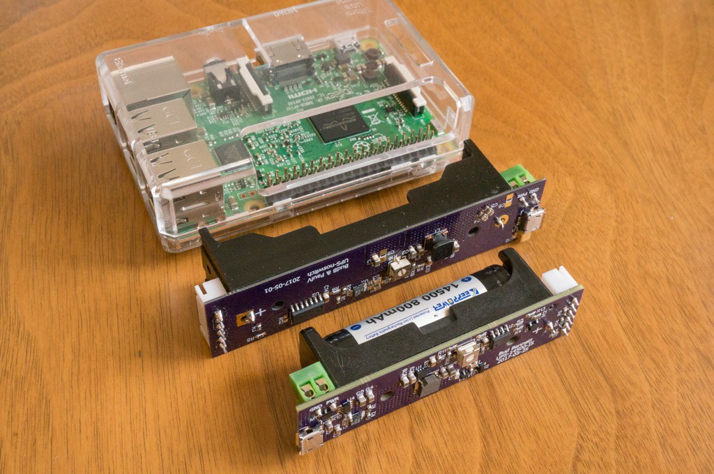
Here's a photo to prove that I actually built this thing. Compare the size with the previous 18650 version and a RPi3B. See how thin that inductor is? It costs 3x the taller inductor.
 It's finally summer here. I have to do some Spring cleaning. The fish are calling...
Discussions
Become a Hackaday.io Member
Create an account to leave a comment. Already have an account? Log In.