mclien
-
send time -not, too-
09/07/2014 at 20:20 • 0 commentsI spend some time today to generate my own signal using this method:
dcf77 , wich is (for the non german speakers) basicly the idea to let a linux machine generate a black/white pattern on the screen. This pattern let the Monitor generate an electromagnetic wave which equals the 77.5 kHz carrier wave for the time signal and is then mudlated to transmit the time information.
After installing some packeges to get the code compiled and setting the xserver to a lower color depth (16bits) I could generate the patterin in a high enought framerate.
For testing I used a common radio controlled alarmclock, which gets the official time signal very well. The signal from the littlt dcf77 programm starts sending ttime at a fake value of 23:23, so success is easily recognizable (unless you run the test at 23:"3, of course). But you can run anny starting time with parameters.
So far I wasn't able to set the clock to my own time with this method. ONly "success" was that I could prevent the clock to get the official time signal while in the range of the monitor, which was sending the fake time.
-
Case Design thoughts
08/23/2014 at 18:05 • 0 commentsThe exapmle case in the picture is a rendering made by sisam with blender. So it' mostly an visualisation of the way it will look like.
Main ideas for the design are those "driver" watches, which will come hany for recumbent riders like me also.
It was asked, if I have any idea how to manufature that. Well, in big sice production it will most likely be a mold injected resin part. For small/ handcrafted/ DYI quantities that's not affordable. So I most like ly will start with parts made in the same way a did another project/hack:
http://hackaday.io/project/2850-WristPDA-%28Abacus%29-Battery-upgrade
(It's not finished by noe, but I'll try to get some usable information ther in only a couple of days. So stay tuned)
-
Licenses
08/20/2014 at 15:15 • 0 commentsIf not mentioned otherwise these licenses will apply for my project:
arduino board: well, I gues that's pretty well documented by arduino.cc and know. Any custom/special board that will come from my project will therefor published under the same license (Creative Commons Attribution Share-Alike)
code/source code: all code generated for this project will be released under the GNU/GPLv3. Code written by other will be marked in the comment/head section.
pictures: all pictures are licensed under the CCbySA
The DCF77 receiver: the one I use so far is made by "Kundo xt" for "Reichelt Elektroni" here in germany. From the documents for it I couldn't firgure out which kind of license it gas. This is to be done.
-
receive time -not-
08/19/2014 at 18:04 • 0 commentstried to get the next step for receiving the time, not just the bits by using the code written by Mathias Dalheimer. UNforunatelly I wasn't able to compile it, same result by using the modified code from Frank Staude.
ONly to realized that this couldn't work, becuse I use an arduino micr which has an ATmega32u4 instead of a ATmega328, so alle the timer variables won't match, of course.
...so: to be continued
-
Display Test
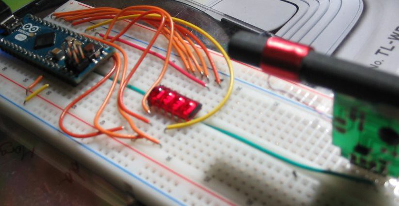
08/19/2014 at 11:59 • 0 commentsYesterday we were testing the display.
Only connecting the display, sisam wrote a code to just display numbers by editing the code of the sketch to have an idea what it looks like
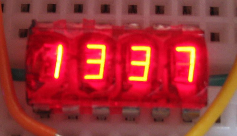
left: breadboard setup, right: displaing 13:37 in full brighness
![breadboard setup]()
![LED]()
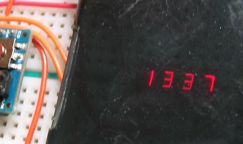
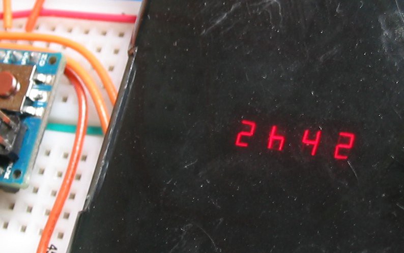
left: Time with grey acryll, right: appointment alarm, appointment in 2h42min
![]()
![]()
Datasheet for the display:
http://www.electronctl.net/Note/BB_QDSP_DS.pdf
Here is the matrix to connet the Display to the arduino:
Display PIN 1 2 3 4 5 6 7 8 9 10 11 12 Arduino PIN 3
pwm0 1 5
pwm4 6
pwm7 2 9 10
pwm11 12 Funktion Cathode
Digit 1Anode
eAnode
cCathode
Digit 3Anode
dpCathode
Digit 4Anode
eAnode
dAnode
fCathode
Digit 2Anode
bAnode
a -
receive test
08/18/2014 at 18:58 • 0 commentsfirst step was to simply connect the DCF77 receive modul to a arduino and see if I get those 0 and 1 bits received.
I used this code:
#define DCF77PIN 2
unsigned char signal = 0;
unsigned char buffer;
void setup(void) {
  Serial.begin(9600);
  pinMode(DCF77PIN, INPUT);
}
void loop(void) {
  signal = digitalRead(DCF77PIN);
  if (buffer != signal) {
  Serial.println(signal);
  buffer = signal;
}
}
after searching a better position for the antenna (don't place it near the computer), I got the 1-0-1-0-1-0 response on the serial monitor. Fine
Smart DCF77 Wirst Watch
A retro style Wirst Watch with a LED segment Display. Receiving time over DCF77 and personal reminders over a hacked/modified DCF77 signal.