I loved the Fotokite Phi project, but for some reason it is not available anymore...
So I decided to test the proof of concept of making my own, based on the cheap X56 frame (it can be ordered as low as 45€ shipped these days).
Event if I didn't want to use the onboard Wifi Camera (it's a poor 0.3Mpix), I ordered the X56W version since it can be remotely controlled by a smartphone.
The frame is exactly what I wanted, small enough to fit a backpack when folded
I originally wanted to replace the control board by a Betaflight / CleanFlight comptatible one, but during the first tests I realized that the Wifi connection between the drone and the smartphone goes through the camera to the control board, and that there is just 3 wires between the camera and the control board.
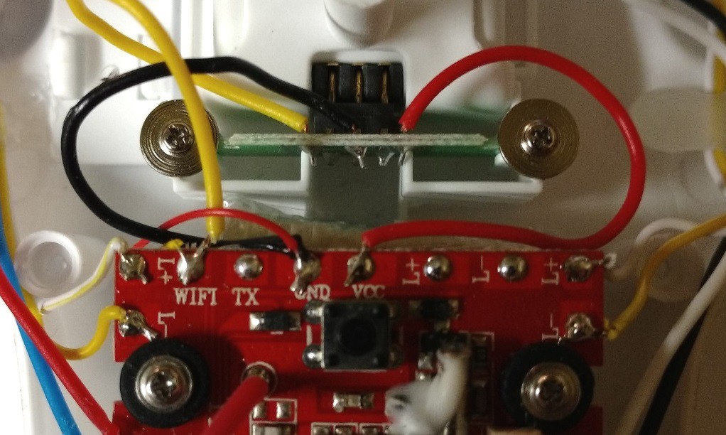 The 3 wires are VCC (3.3V), GND and 'WIFI'.
I guess that even on the X56 without 'W' the control board should have these solder pads.
Then I tried to investigate this 'WIFI' signal:
 Fine ! It's just a basic Serial link, transmitting 10 Bytes at 19 200 bauds !
Now a bit of reverse engineering:
The bytes are in order:
Byte 0 : Throttle (Int8 value - 0x80 in the middle position)
Byte 1 : Elevator
Byte 2 : Rudder
Byte 3 : Aileron
Bytes 4 to 7 are trims for the 4 previous axes (nominal value is 0x20)
Byte 8 : used to transmit extra information (like flip commands) 0 as default
Byte 10 is a checksum
It took me some time to understand how this checksum works (it's not easy to connect the logic analyzer with rotating motors...)
Finally the checksum is not so difficult to compute :
CHK = 0x55 + ( Byte0 XOR Byte1 XOR ... XOR Byte 9 )
This serial link is an opportunity to investigate the possibility to control this guy using just a regular UART link instead of the more complex PPM / SBUS signals, saving cost keeping the original control board.
I'll try to connect an ESP8266 chip to drive the control board as the next step.
 night.dav3
 danielmiester
 Mateo Estigarribia
 hebel23
 Tanmay Karpe
ATM I tried to bind it to my flysky fs-t6, but without a multi protocol unit it isn't possible I think. Anyone tried it?