The actuator body has now been designed for fatigue and to meet the requirements for Shapeways 'strong and flexible' sintered plastic (PA / polyamide / nylon 12).
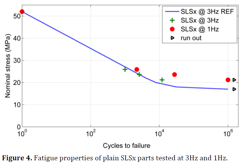
The material data for this is available by searching for PA2200 material data sheet. The stress limits come from a paper I found [ref. High cycle fatigue properties of selective laser sintered parts in polyamide 12] the key findings of which are;
- The building orientation of the SLS specimens has no influence on the fatigue properties, due to high percentage of fusion.
- The fatigue life is significantly influenced by cyclic softening if the sample temperature reaches the glass transition region, leading to brittle fracture.
- Where the print machine employs contour scanning the outer surface is of higher quality, damge to the surface by machining reduces fatigue life as cracks nucleate from unmolten powder particles and these are not present on the unmachined surface.
 The design followed an itterative process from the initial design, extending the length of the thin hinge material. Initially simply, but when I found the fatigue data a more radical solution was needed to get the stress below 18MPa for a 1.5mm deflection. This necessitated meandering the thin hinge material to fit the length between the attachement points.
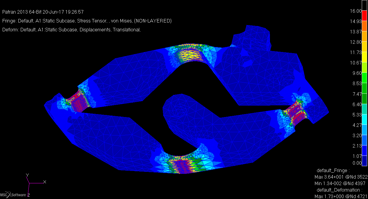
The stress analysis was carried out using MSC Patran as this is what i've been using for the last ten years at work. The model was held at the motor attachement point and the pin displaced by 1.5mm.
Below are plots of the stages of development to the final design.

Figure: Von Mises stress plot (MPa / N/mm2) clipped at 16N/mm2 showing the stress in the part. Initial design first run.

Figure: Stress plot (MPa / N/mm2) clipped at 16N/mm2 showing the stress in the part. Prior to re-design for fatigue stress limit. Investigating the behaviour of the stress and flexure to extension of the hinge length.

Figure: Stress plot (MPa / N/mm2) clipped at 16N/mm2 showing the stress in the part well below the 10^6 cycle stress of 18N/mm2.

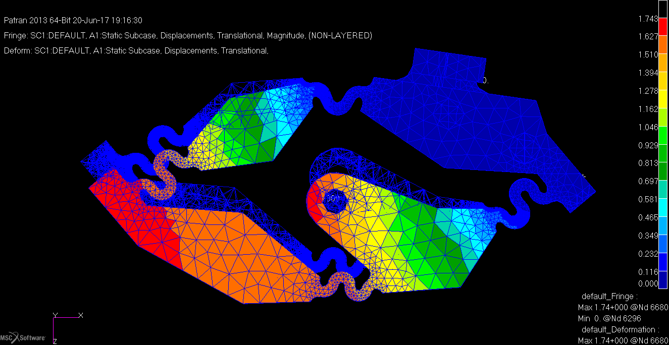
Figure: Displacement (mm), because of the constraints the movement looks a little odd, but is correct.

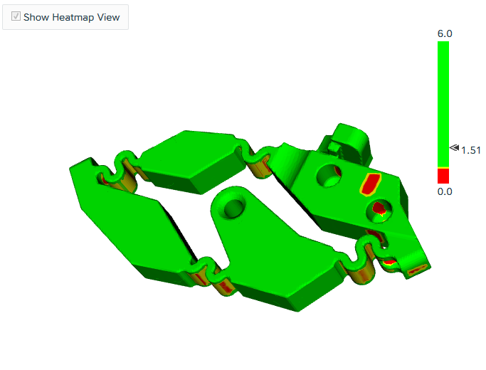
Figure: Allowable minimum thickness plot from shapeways web page, areas in red are below the minimum 0.6mm. I'm not worried by the limited areas and it passes their automated checks.
 David Brown
Discussions
Become a Hackaday.io Member
Create an account to leave a comment. Already have an account? Log In.
Great work, most useful, thanks.
Are you sure? yes | no