Bob Baddeley
-
Installation and Results
10/21/2017 at 23:08 • 0 commentsInstallation was trickier than I expected. First, I was using a power supply that wasn't good enough. After plugging in a few some of them stopped working or would work erratically, or would flash improperly. Something was up. I upgraded the power supply and that fixed it. I suspect that there may still have been some voltage sag by the end of the strand because the blues weren't as bright at the end of the strand.
I also made the mistake of trying to put them up before plugging them in. Because of this, whey weren't synchronized, so I had to take them back down, turn them on, and leave them on and synchronized while I installed. It's a real pain to synchronize them once they are in the tree because you have to press the button on the top of the icicle.
Once I had the stupid stuff figured out, installation wasn't that bad. I made a tool with a hook at the end of a long handle and used that to help place the strands where I wanted on the tree. I also threw them up to get them where I wanted. If doing a really tall tree, it may be difficult to get the icicles up into the higher branches.
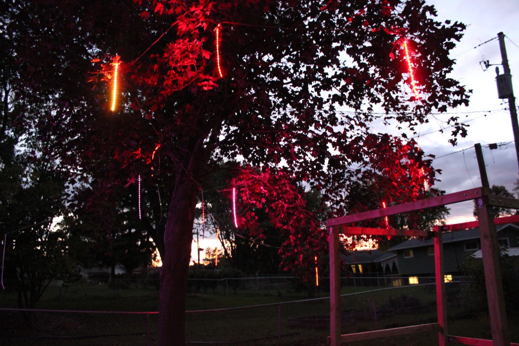
Anyway, we had the lights installed and everything looked great. We had a deadline for the Jewish celebration of Sukkot, and we had a big party in the back yard. The lights looked fantastic. We chose the "fire" mode, which makes the icicles look like they're on fire, and because they're so bright, it gives the area under the tree a flickering fire like glow as well. The party was fun and we forgot to get video of the icicles in action.
![]()
This doesn't really give a good impression of the motion of the icicles, which is a big part of the whole point, so here's a little video of the icicles doing one of the "drip" modes:
The feedback was great. Everybody loved them, and in fire mode they added to the actual flames from the fire pit that was started later. In the front yard they were in another tree and helped guide people to the party. The neighbors thought they were cool, too, and they've had bicyclists and drivers rubberneck as they go by.
-
Assembling a Batch
10/12/2017 at 15:38 • 0 commentsAssembling one on the bench and testing it is one thing; making 30 requires a lot of careful planning and repetitive steps.
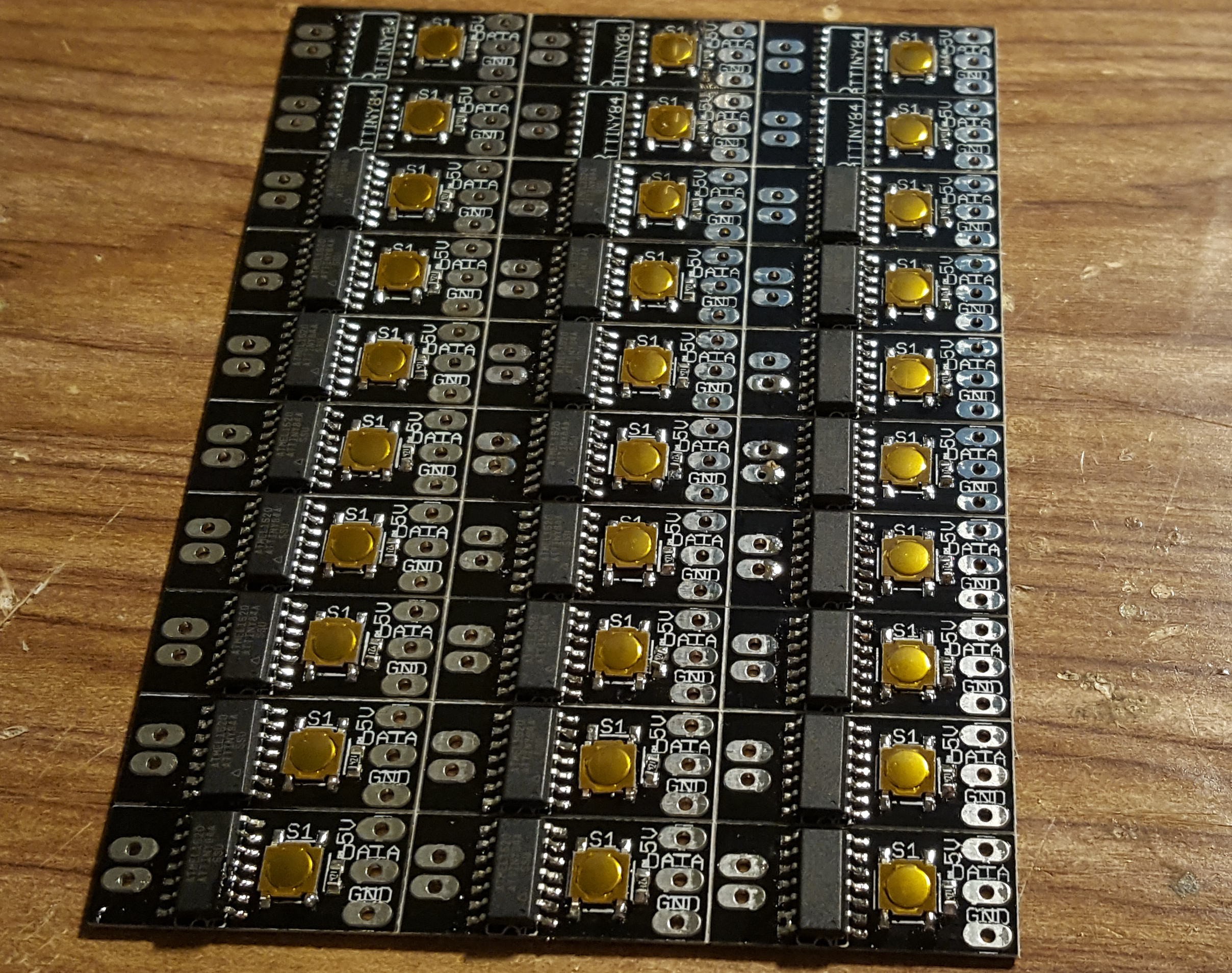
The PCBA part was easy. I laser cut a stencil, populated a bunch of boards (it was only 3 components per board!) and did a quick job on the hot plate.
![]()
The LED strips come with the silicone sleeve on it. I needed to remove the sleeve so I could cut the strips and the sleeves to different lengths (to allow for the PCB to fit into the sleeve. This leaves a little bit of extra LEDs at the end that don't have a sleeve. Since I'm doing 20 LEDs per icicle, and the strings come in sets of 150 LEDs, that's 7 icicles plus 10 LEDs left over anyway, so it works out ok.
Removing the sleeve was a challenge until I discovered an easy way to do it. The friction was very high between the LEDs and the silicone, but if I unwound the whole roll and had someone hold the LEDs on one end and I pulled the sleeve from 5M away, it all slid out very quickly and easily. After cutting, I used silicone sealant to seal the bottom 1/4" of the sleeve. It turns out that there are already caps available to purchase that would have made this significantly easier. Oh well.
![]()
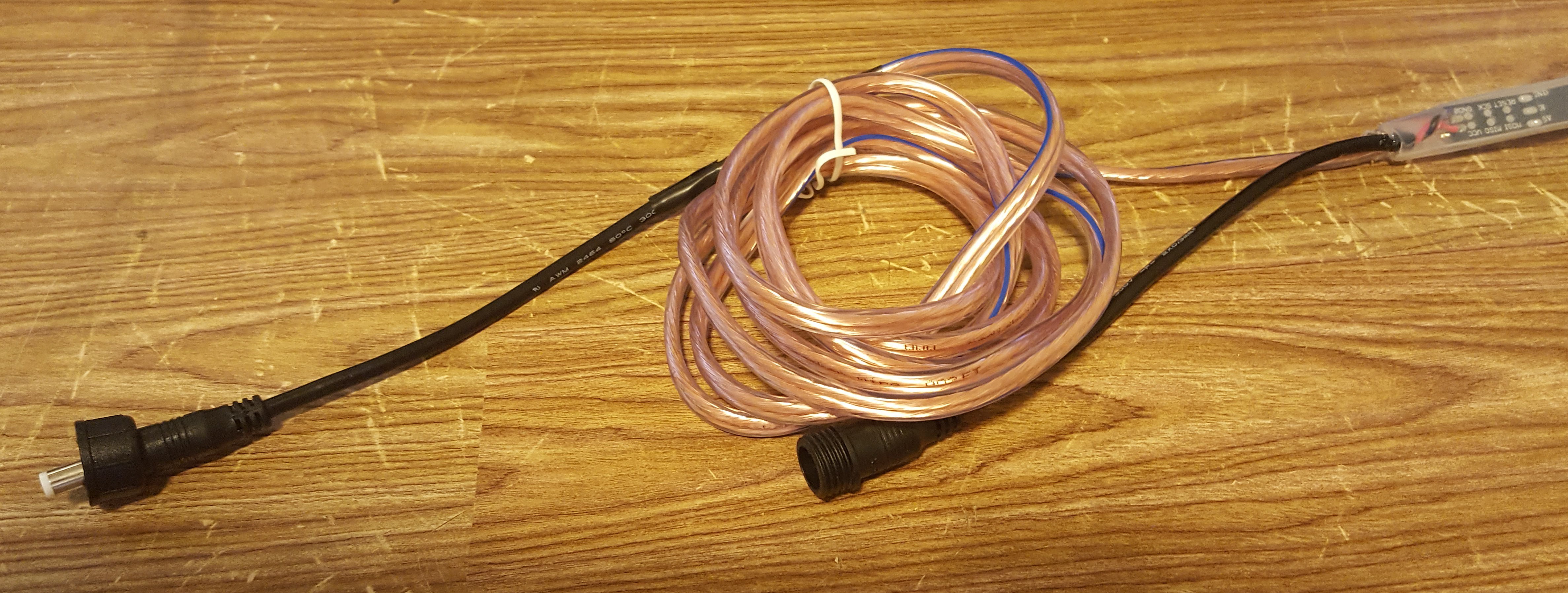
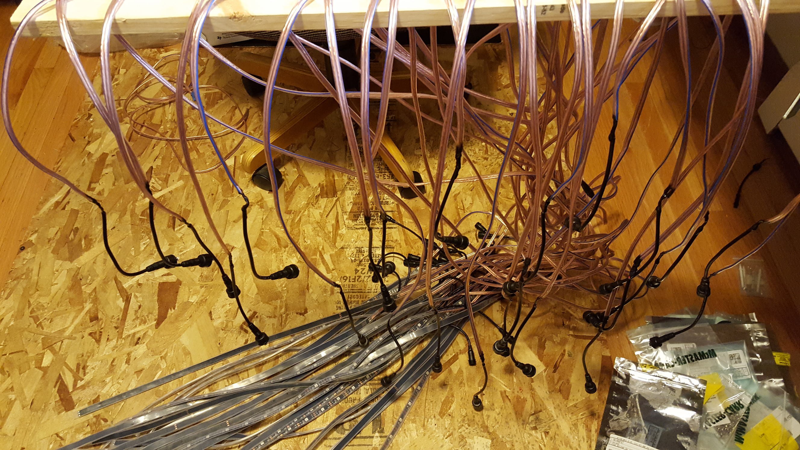
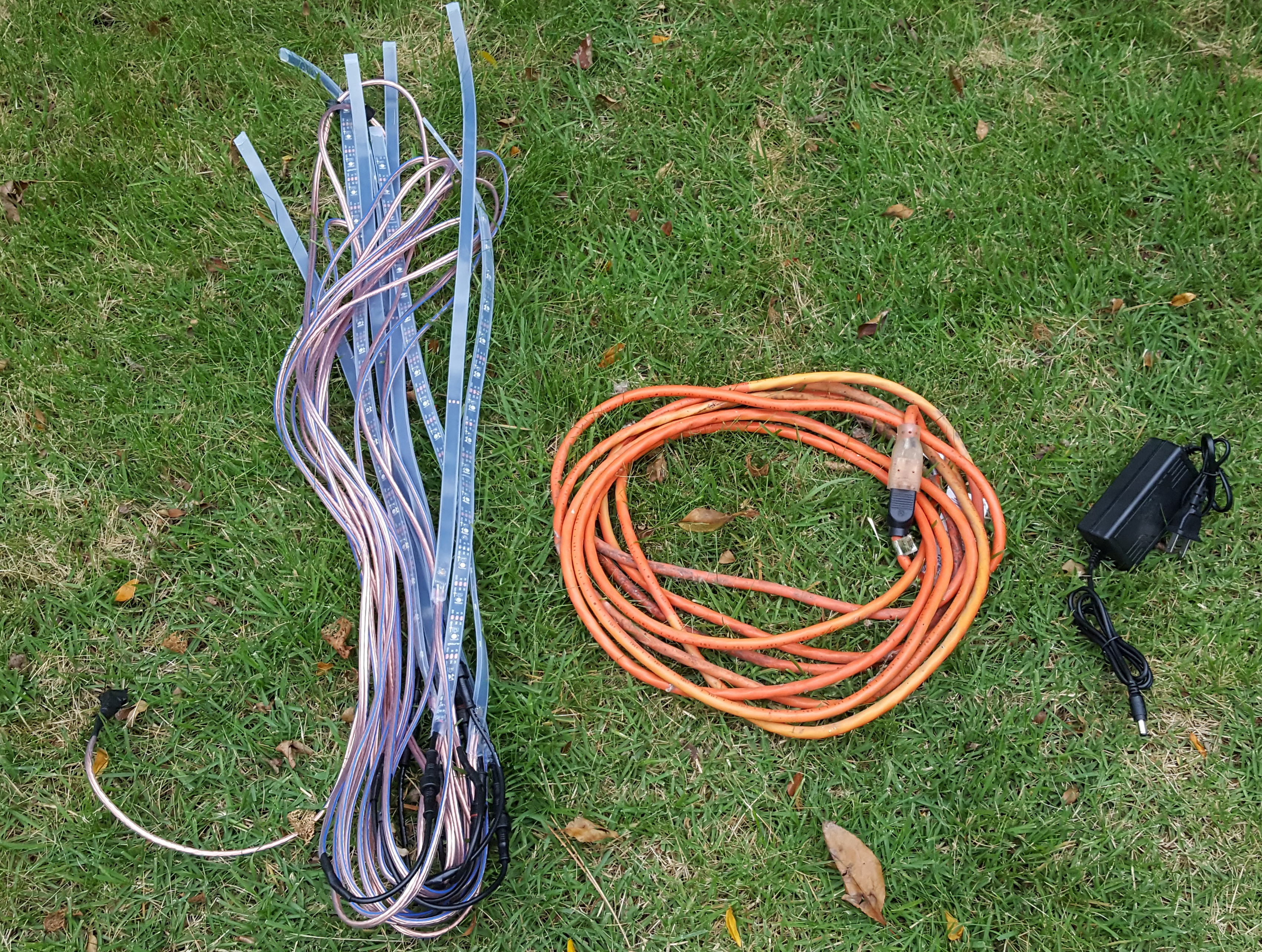
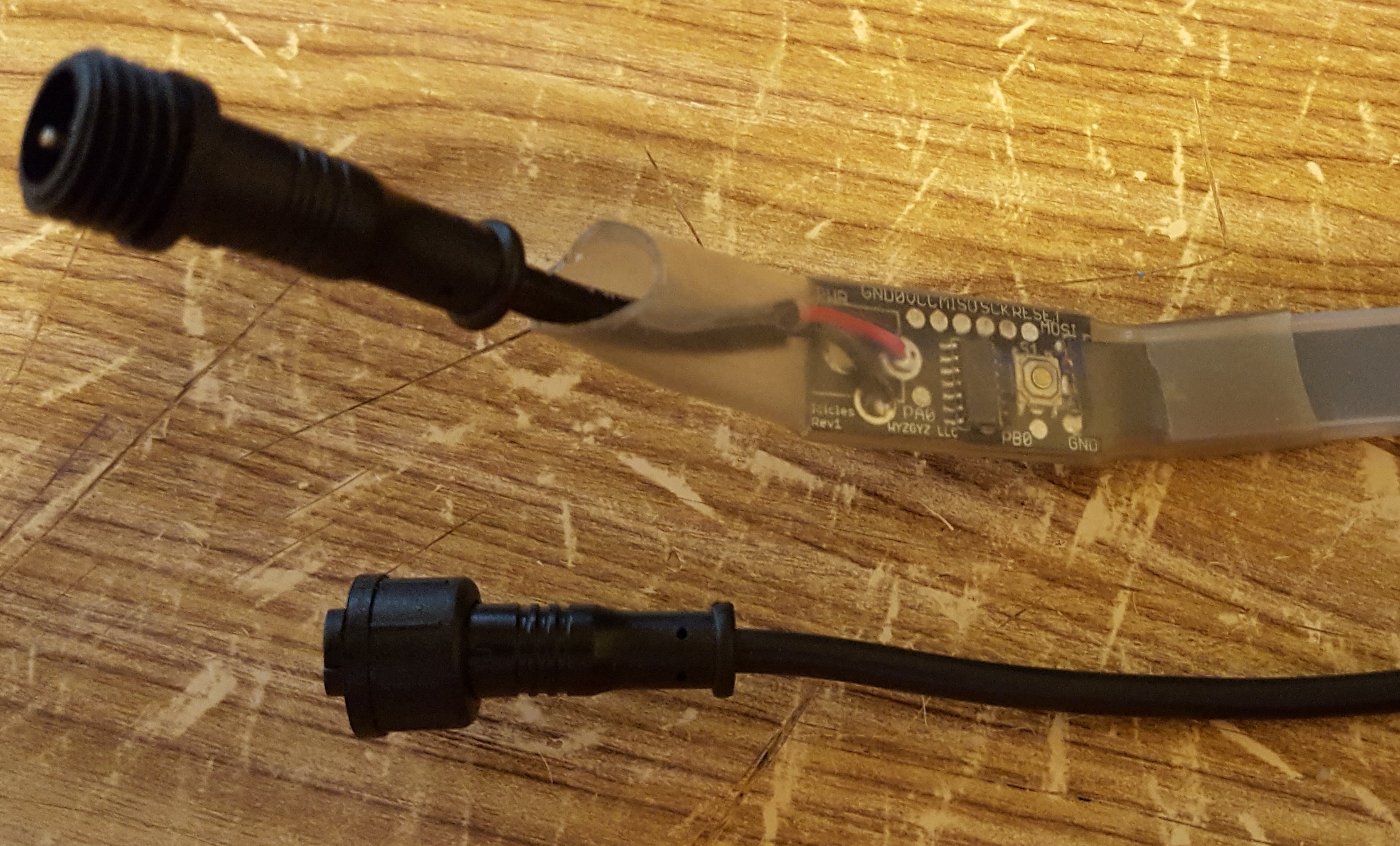
Next I soldered the PCB to the LED strips, and then two connectors to the PCB. For the string I decided that instead of a single cable that was tapped every few feet I'd make a bunch of discrete units, with one short connector and its mating connector at the end of a 6' cable. This way I could string them all along easily and they could be combined into any length.
![]()
Attaching the connector end to the cable was a little messy. I used some brush-on electrical tape, then when that dried I wrapped regular electrical tape. It had to be mechanically secure, as there would be tugging going on (especially when setting up and taking down the strands). I set up a small assembly line for this.
![]()
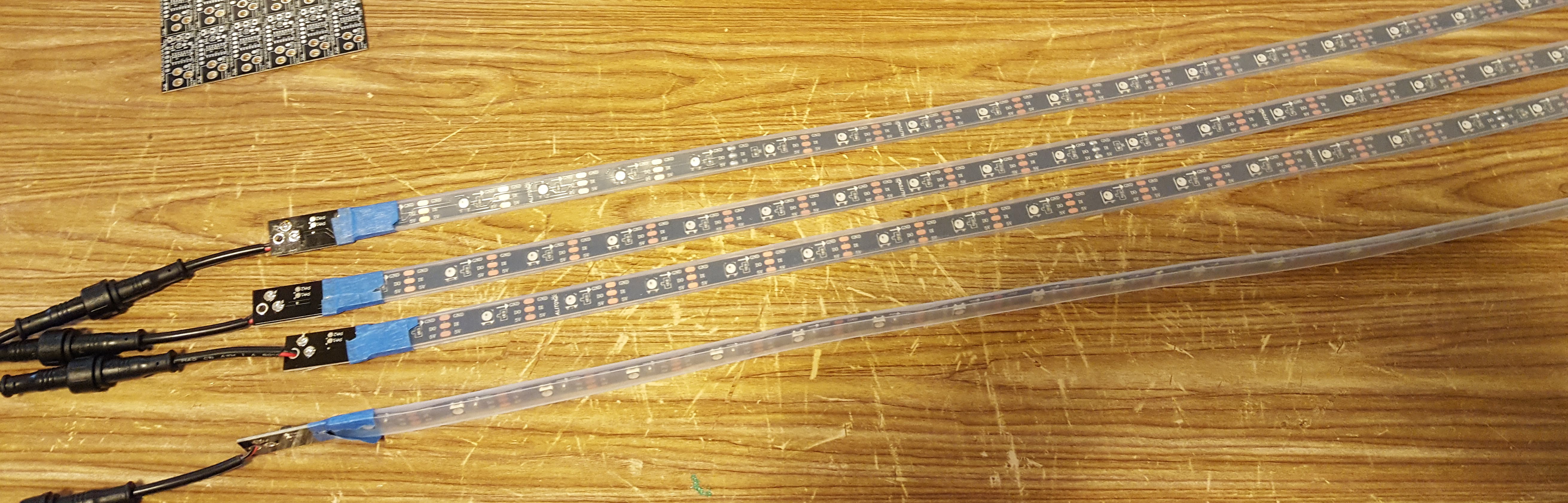
Here are the first 10 ready for installation in a tree.
![]()
-
New PCB
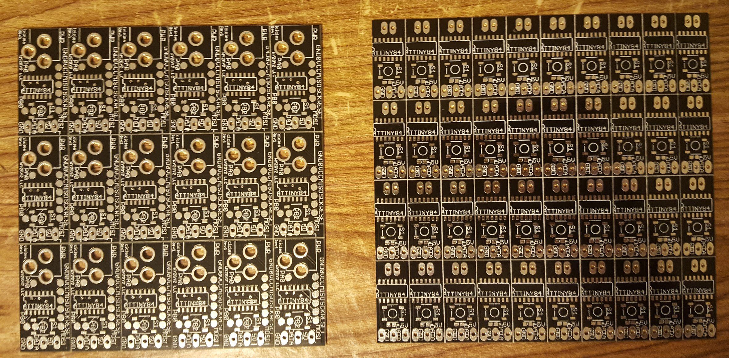
10/12/2017 at 15:10 • 0 commentsFiguring out the enclosure for the PCB was a disaster. I couldn't make it waterproof or find something easy that would work. Then I had a revelation. The LED strips are already coming in a waterproof silicone sleeve. Why not use that? I redesigned the PCB so that it was thinner (the same width as the LED strip), and tried again. When the new boards arrived, I populated a bunch and tried it out. Success! The new PCBs are smaller, so I can panelize more to a board. For $4.90 I can get 10 boards of 10x4, or 400 pcbs! The previous board was 6x3, so 180 for $4.90. I just halved my PCB cost and eliminated the need for a separate enclosure, and reduced PCBA cost because it's more dense!
![]()
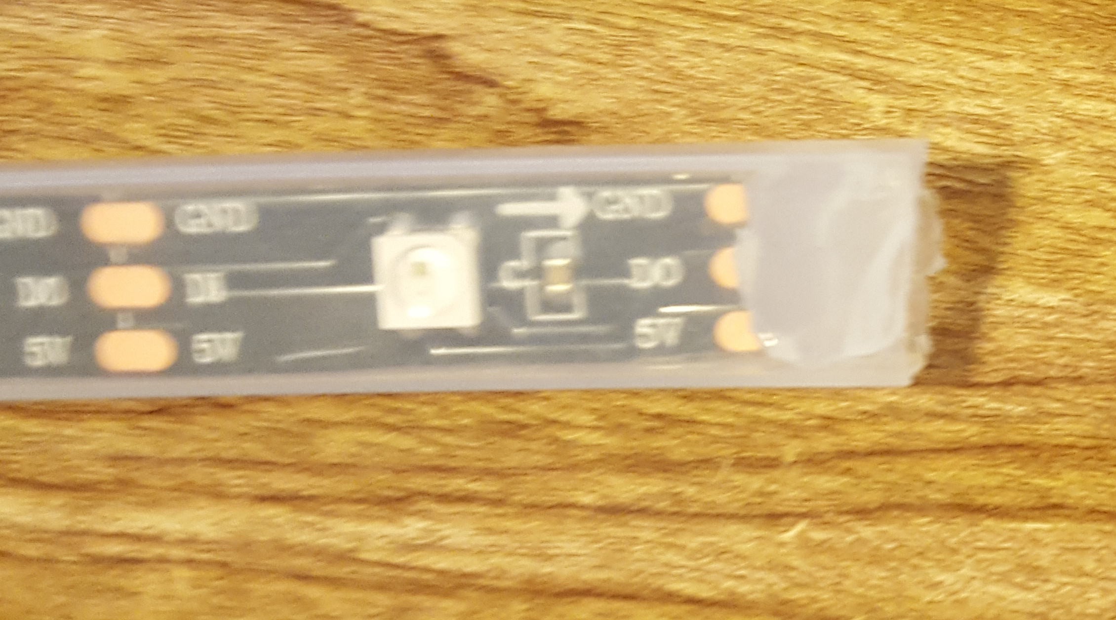
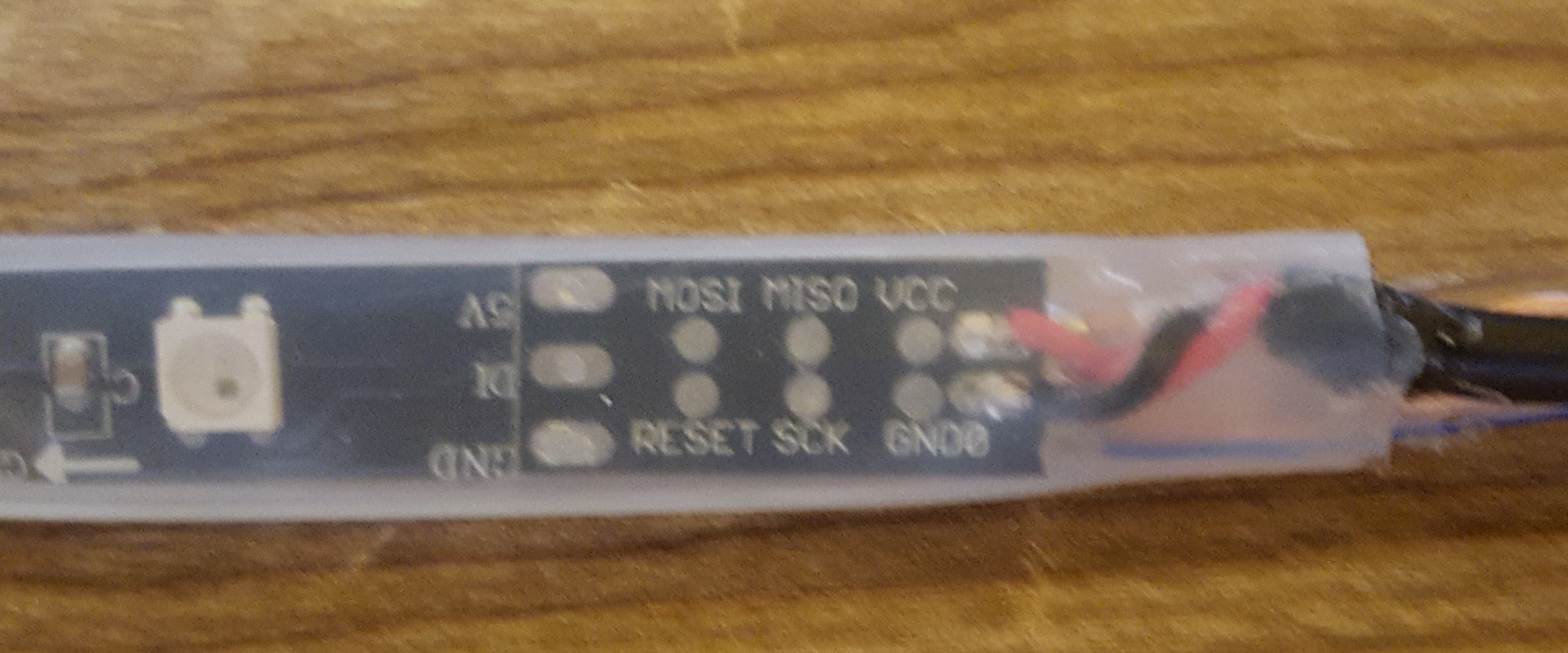
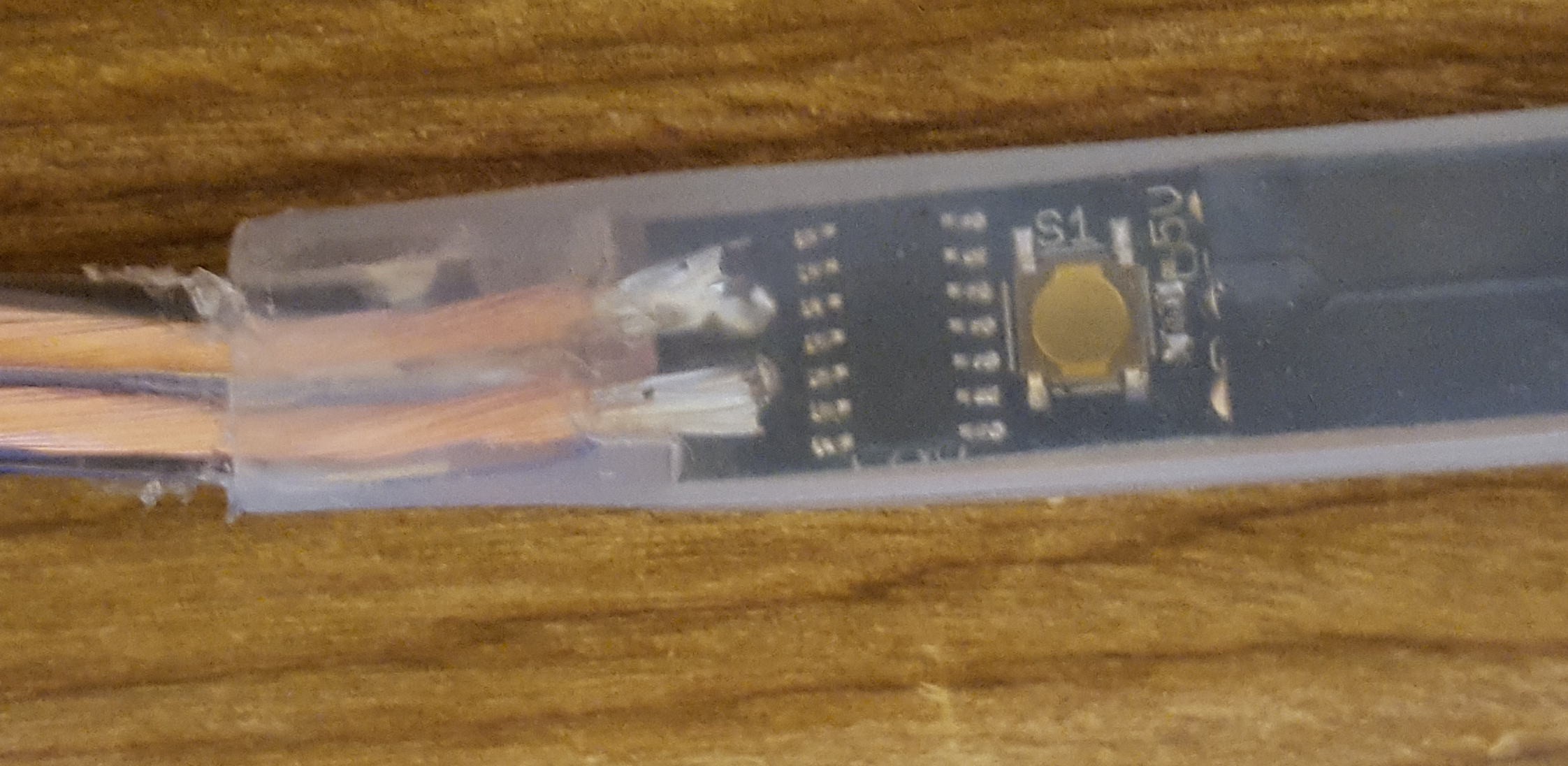
After assembly, here's what they look like slid into the silicone sleeve.
![]()
![]()
You may be asking yourself why the LED strip is upside down in its connection to the PCB. I don't really have a well-thought-out reason for this. The strips came with the 5V and GND in different places than I expected. It makes absolutely no difference, though.
-
Estimating Cost
06/17/2017 at 15:33 • 0 commentsIf this is going to be a product, I have to be able to sell it and make some money. Typically the markup would be something like 3-4 the COGS. Since I'll sell it online only, I can get away with 2x. So, looking through all the components, how much can I estimate for a sale price?
Part Link Quantity Cost Cost Extended Bulk Estimate Bulk Extended Totals $114.83 $60.94 PCB Smart-prototyping.com 10 0.04 0.4 0.04 0.4 ATTiny84 Digikey - ATTINY84A-SSFR 10 0.7 7 0.7 7 Button Digikey -732-7029-1-ND 10 0.47 4.7 0.324 3.24 WS2812B Strip Amazon - B01N07A6NP 10 3.46 34.6 0.75 7.5 Silicone
10 0.1 1 0.1 1 Connector Amazon - B01EPLAN42 10 1.488 14.88 0.5 5 Liquid Tape
10 0.1 1 0.1 1 Enclosure
10 1 10 0.6 6 Power Supply Amazon - B019P1HGME/ 1 9.99 9.99 10 10 Power Supply Switch Amazon - B00ME5YAPK 1 5.99 5.99 3 3 Wire
1 11.99 11.99 6 6 Power Supply Enclosure Polycase - hd-45fmmt 1 13.28 13.28 10.8 10.8 This assumes 10 strips per unit, a 100 foot line, and power supply. It's just raw materials and not time or shipping. That means even if I purchase in bulk, I'm going to have a cost of goods sold around $100 assuming the labor involved is not too time consuming. After the first tests, it might take an hour per set of 10, so $100 for COGS seems reasonable. That means I have to sell these strips for $200 in order for it to make sense. They are pretty cool, but most dumb light sets (LED) sell for $30 or less, so I'd have to show a lot more value. I don't know. Maybe people will buy them. I'll have to work on marketing.
-
One Button UI
06/17/2017 at 00:54 • 0 commentsI have one button for this project, and I keep adding features. How complicated is it going to get?
Here's the UI that I have now, and it seems to work pretty well:
- On power cycle, it will increment the mode. This is an easy way to remotely switch through different modes and keep them all in sync. If the user wants to keep the same mode all the time, they should leave it on. Alternatively, if this is used in a scenario where it is turned on once daily, the user can just spend a few seconds cycling around until it gets to the mode they want.
- The button on the strip itself will increment the mode if pressed briefly. This allows the user to re-synchronize the strips if somehow they get out of sync. It increments on release.
- If the button is held for 2 seconds, it goes into brightness adjust. The lights will all turn white, and every two seconds the brightness of the lights will increment. This will continue until the user releases the button. This brightness level is saved in the EEPROM. When the button is released the LEDs are no longer white and the strip resumes the mode it was in before the brightness was adjusted.
That seems to be pretty good for a single button. My hope is that when the user is installing the strip they'll be able to set up the lights with the brightness they want and make sure the modes are all synchronized. Then when the installation is complete and they may not have access to the strips, they can still adjust the mode by cycling the power.
-
Night Test
06/15/2017 at 03:16 • 0 commentsI took four strips and attached them to a power supply at 5 volts. Everything worked great! I did notice, however, that they start off synchronized with the same random seed, which means that they're displaying the same drips even when they shouldn't. I'm going to have to fix that.
I will also have to come up with a solution for the wire. Something that will be waterproof and permanent.
I still need to put in the code to adjust the brightness with a button press.
-
Temporary "Enclosures"
06/14/2017 at 21:22 • 0 commentsThe device can be sealed and waterproof. The LED strips already come with a silicone like sheath. I'll need to cap the bottom end, but I'm thinking of squirting some silicone into the bottom. Just regular caulk like material.
For the top part I got waterproof connectors, which makes it easy to disassemble, but since one has to wire the other side of the connector up, I wonder if it really is that much of an advantage to use any connector at all, other than if one wanted to leave the wire up year round but take the strips down or replace them occasionally? I'm not sure.
But an enclosure for the circuit board is necessary, and I guess that's why we need a waterproof connector. I first thought about shrink tube, but I don't know if I'll be able to find something large enough for the PCB but that shrinks enough to seal around the thin wire. My first experiment was a failure. Also, the shrink wrap was tight enough that it pressed the button permanently. So shrink tubing is not going to work.
![]()
My next idea is regular tube with caulk at either end. It won't be pretty but it will get me through the next round of testing, which will take place outside.
-
Rev 1 working on the bench
06/10/2017 at 14:18 • 0 commentsToday the PCBs arrived. I ordered them through Seeed's Fusion because they were only $4.90 for 10 panels of 6x3, so I got 180 PCBs at about $.03 each!. Surprisingly they came V-Cut, too, so I'm a super happy camper. Shipping was about $30, but I was getting another PCB for a different project so it was still cheaper than a dime each for a custom board.
![]()
The first step was populating them. There are only two components; an ATTiny and a button, so making a few units was dead simple.
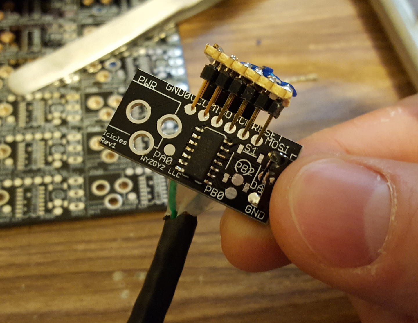
Next was the programming jig. I had an Arduino as an ISP with the standard 3x2 header, but for this board I made it 6x1, so I had to build an adapter. I like doing my programming headers at .1", so making the programming cable/adapter is done on regular perf board. I decided not to use spring pins or pogo pins and instead I just used a strip of male header. If I press it against the PCB it still works well. It took a couple tries and some stupid mirroring mistakes, but eventually the programmer worked and I was off to the races.
![]()
The WS2812B strips lit just fine with the test code and I then switched to firmware development. I started with some code from a different project for managing the LEDs with an ATTiny so I had a leg up here and mostly just needed to refine for the number of LEDs and add some new features like the power cycling changing the mode. I still need to implement the brightness control with the long press.
![]()
I'm happy with the waterproof connector I've chosen, but I really need to figure out how to seal the PCB and offer strain relief on the connections, plus also make the button work. It's going to be interesting.
Next up is a functional test in a tree to make sure it looks good and evaluate my choice in the number of LEDs in the strip. I don't like how the strip is black on the backside, so I may have to double it up.
LED Icicles
Hanging WS2812 strips from a tree like glowing icicles. A few modes for fun.