Matthias
-
Purple PCBs :) Also: Assembly
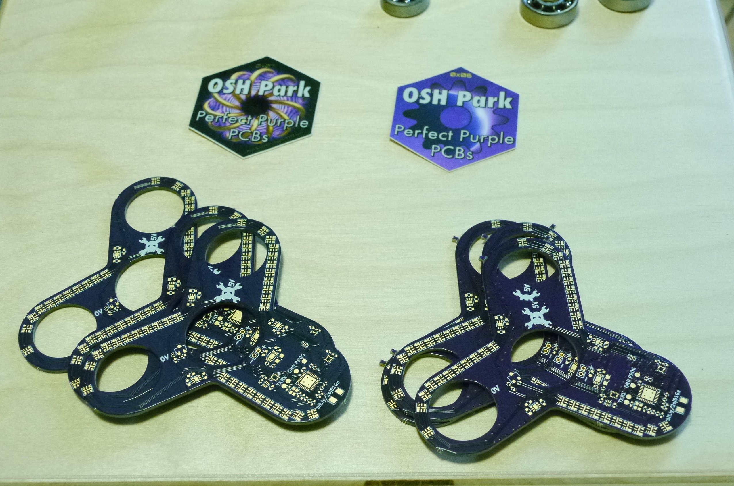
06/27/2017 at 00:46 • 5 commentsToday, a package with my PCBs arrived. Actually, it was two packages, because I messed up the orders (as you probably read in my previous log).
![]()
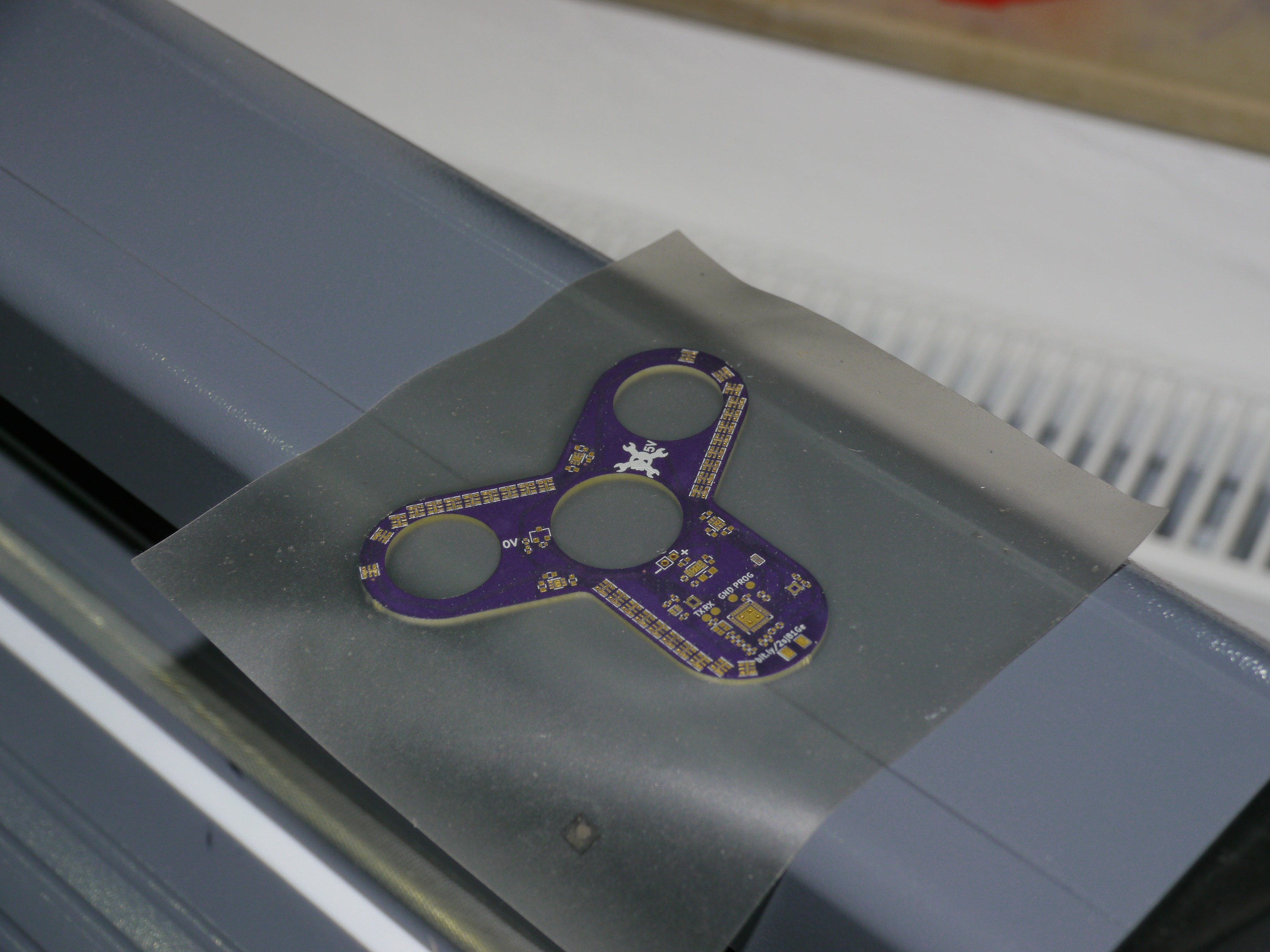
Armed with almost all the required parts, I started assembly. First, I cut out a stencil on my vinyl cutter. While my vinyl cutter produces fairly low quality stencils which don't work reliably work with .5mm pitch QFNs, these stencils are almost free for me. So for a single PCB, that's fine.
[I will add a video of the stencil cutting right here...]
The finished stencil applied to a PCB:
![]()
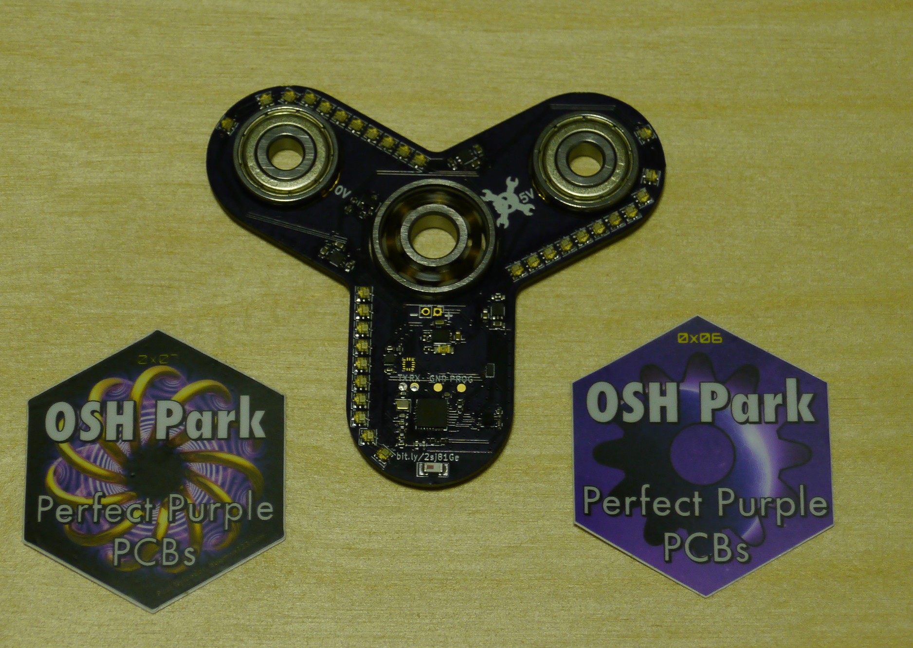
Next, I added some solder paste and all the parts. Placing 32 LEDs tends to be a bit tedious, but I got through it just fine. After touching it up a bi, the PCB now looks like this:
![]()
Since I need electrical contact on the outer bearings (they will be used for charging), I used the battery contacts I described in one of the earlier logs. They fit really well and are even able to hold the bearings in place.
![]()
Tomorrow, I plan to finally mill the back cover, upload the videos (both of stencil cutting and milling), put everything together and finally do a smoke test. Hopefully, the magic smoke will stay inside...
-
A big thanks to OSH Park
06/15/2017 at 23:44 • 3 commentsAs some of you remember, I already ordered my PCBs. And I totally messed up. I didn't check which version I uploaded (although I always put the git hash in the name of gerber-zip. Shortly after my last log, Drew from OSH contacted me and upgraded everything - shipping, fast service, etc. I was very impressed by them and happy about getting the PCB really soon.
So later today, I got the message that my board had been sent to the fab. And as I read that mail, it hit me - I had sent them the first version of the board, not the newest one. So I asked them if they could still change it, on the off chance that they could. If they couldn't I would still have a working PCB, but not with all the bells and whistles that I had added later on. Of course my assumption was correct - once the design hits the fab, it will be produced that way.
However, after they had sent me a coupon for my first order, they sent me a new one. This time enough to cover fast shipping, and express service right from the start. This is not what I expected. I mean - I messed up, yet they are willing to make up for my mistake. They went above and beyond any expectation I had. It's seldom that you experience this kind of customer service from a company.
Because of this, I want to express my deepest thanks to OSH Park! You guys rock! Thank you!!!
-
Hackaday, ordering parts, locking in the design
06/14/2017 at 08:38 • 2 commentsSo a lot has happened since the last update. First of all, I have been featured on the main site. That probably wouldn't have been possible without all of you, who followed and liked my project. So to thank you all, I decided to step up the speed a bit:
I already ordered all the parts so they'll be here by the weekend. For the ESP8285 and APA102-2020, this meant ordering assembled boards with the parts on them as availability of those is otherwise very bad in Germany. Sadly, I won't be here to try assemble everything, as I'm going to London from Friday to Tuesday.
As some of you might have noted, there has been a last minute change on the design - the center hole is now sized for an 608 bearing. That way I can use 608 bearings with a greater availability for the center. Especially, when it comes to ceramic bearings and the like, they are simply cheaper.
TL;DR;
Thank you, followers and likers! I'm doing my best to show some results very soon.
Quick update: I just ordered the PCB.
-
Power management
06/13/2017 at 10:39 • 0 commentsAs mentioned in my last log, I wanted a way to wake the spinner up by moving it. Also, I want to be able to have the ESP8266 "completely" turn off power until the spinner is woken again. Last but not least, I wanted some kind of relatively fail safe under voltage lockout.
![]()
My solution to these problems comes in the form of a little chip made by Silego, the SLG46140. It is a very useful little programmable chip - more or less a mixed signal PLD. I could have chosen a smaller version, but the SLG46140 is the smallest one that is also supported by open source tools, so I thought that would be nice. Even though I am currently using the Silego tools, that is the only proprietary software I use(d) while designing this project.
So back to the fun stuff:
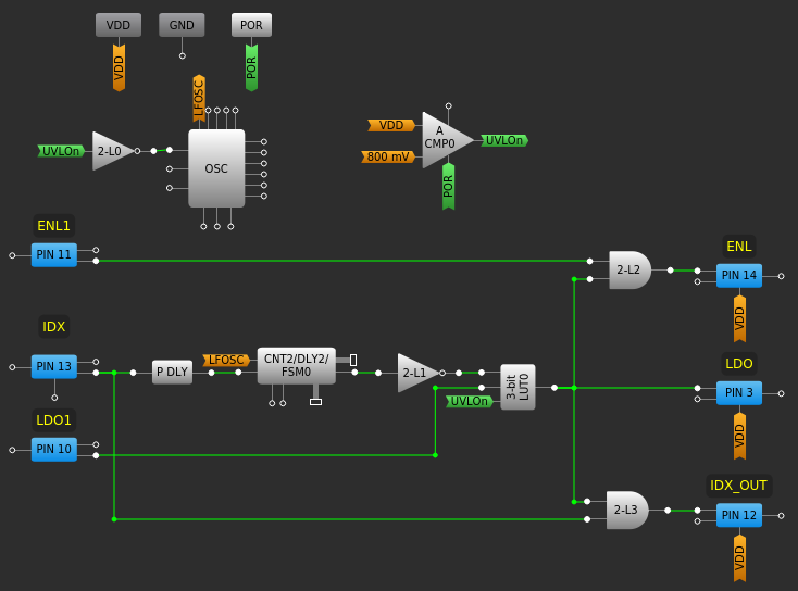
![]()
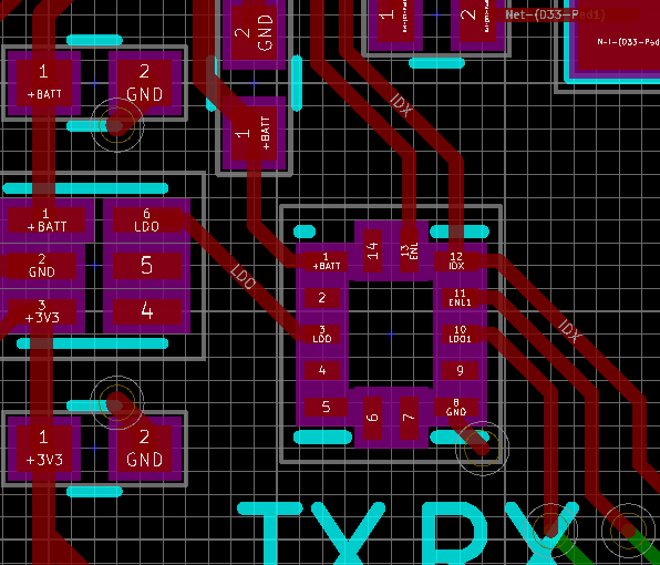
What you see here is my design for this chip. As it handles all the stuff described above, here is a little breakdown:
Most importantly, I use an analog comparator (CMP0) to make sure the battery voltage is above 3.0V. The hysteresis is configure to make sure that the voltage reaches at least 3.2V before setting UVLOn again after it dropped below 3.0V.
Next, I use P DLY to detect falling edges coming from the hall sensor. This signal is - together with a roughly 109Hz clock - fed into CNT2. CNT2 is a counter that counts up to a value of 43, which takes about 400ms at 109Hz. When it reaches this value, it does not automatically reset, but stays there and turns the output on until it is reset. By inverting this signal, I get a signal that is high for 400ms and then turns low if the hall effect sensor does not encounter a new magnet within those 400ms.
The LDO is controlled by the pin labeled "LDO". It is configured as a push-pull output. To control this signal, I used LUT0. This LUT is configured as UVLOn && (!CNT2 || LDO1). Therefore, if the battery voltage is above 3.0V, the LDO is on for 400ms after every turn or longer, if the CPU wants it that way.
So here, we already have the whole wake up by spinning, go to sleep from CPU stuff solved.
The remaining circuitry is relatively uninteresting. It only makes sure that the LED regulators can only be turned on if the LDO is on and also, that the CPU can not mess up the index signal when it is turned off. Since the CPU is running at 3.3V, while the PLD could have up to 4.2V running through it, IDX_OUT is configured as open collector and the CPU has to enable an internal pull up to 3.3V.
-
Low Power and Index sensing
06/13/2017 at 03:16 • 0 commentsAfter some careful consideration, I went back into KiCad and replaced the VCNT2020 by a TLV4946-2K. This means that I will use a hall effect latch instead of the optical sensor I initially planned to use. I did not plan to use this sensor as I got tired after sifting through a few pages of hall effect latches on mouser only to find them relatively huge or slow.
The size is an issue as I want to keep a total thickness of about 8mm and I am already stuck with a 1mm wall supporting the battery. Of course, I could go a little thinner, but I would rather not. Thus, all through hole parts are instantly out of the question, while a lot of regular SMD parts are as well.
Slow sensors are also not an option since a sensor with 50Hz or 3000rpm means I would have no room to spare. Since I would really love everything to work even with compressed air, that's not really an option either.
These considerations initially lead me to select a very thin optical sensor and call it a day. However, there was on issue that kept me thinking: optical sensors draw quite a bit of current. That also means that my dream of using the index sensor to wake everything up would not have been possible.
So today, I went back and sifted through a few more pages of datasheets until I found a sensor that fit my bill. At up to 15kHz it's a lot better than the ones meant for detecting a closed display. I might even be able to use multiple magnets as described by [hyperneurone] in the comments.
I already updated the files on github and will now try to come up with a circuit that allows me to disable the LDO from software until the spinner is spun. That way I could get great standby times.
P.S.: I already ordered the parts that take longer because they are not available at Mouser. In this case, that's the two most important parts: ESP8285 and APA102-2020.
-
Mechanical stuff
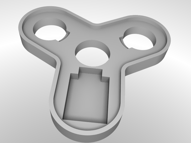
06/11/2017 at 02:03 • 0 commentsI finally got around to designing the part that will hold everything together. As you can see, there is one hole for the battery at the bottom and the outer bearing holes also have some free space for the charging contacts. They will be mounted on the bottom of the PCB and be used to get power through those bearings. This way, there is no disassembly required for charging. And given that I can only fit a 240mAh LiPo in there, it won't last very long if you use it at the highest brightness. The LEDs can draw up to 3*150mA@5V while the ESP will probably be in the 100-150mA range. So you will get less than 20 minutes at full blast. Under normal conditions, I estimate more like 1 hour of use with pictures or a few hours if you display messages inside. And even with an empty battery, you can still use it as a "dumb" spinner.
So here is the part that keeps everything together:
![]()
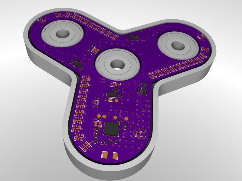
And here it is with the PCB "mounted": (I was too lazy to get everything into FreeCAD just for rendering)
![]()
-
PCB "done"
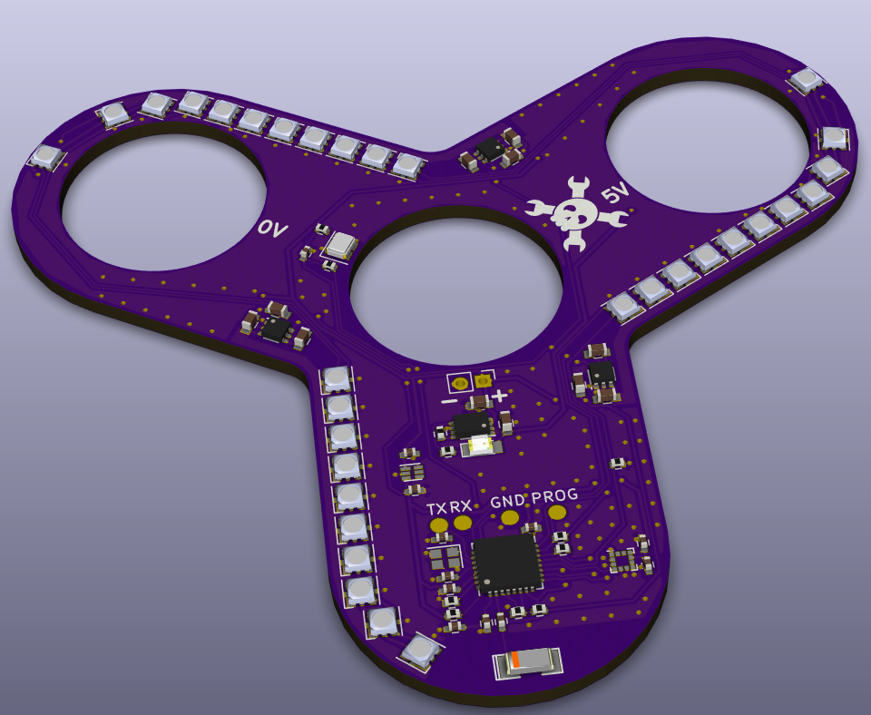
06/10/2017 at 15:15 • 0 commentsThe PCB layout is finally done. There are a few things that can be improved, but I'll probably leave them for later. It's very likely that some minor fixes will be required, so the improvements can be done at the same time as those fixes. One thing I had completely forgotten was the fact, that the reverse voltage protection is not needed - it's already integrated in the charger IC.
Since I read the email that [OSH Park] started following me while I was mostly done, I decided to make the PCB purple. I also added the jolly wrencher.
![]()
All current files are on Github.
-
APA102
06/09/2017 at 16:31 • 1 commentAs I was just asked about the ability to hit a sufficient refresh rate with the LEDs, here are my thoughts on the matter: With WS2812 and similar ones, it would be impossible, but apparently not with the APA102. From the information I gathered, the APA102 can be controlled with a clock of at least 8MHz. With 32 LEDs, I get at least 8(Mb/s)/(32b/w)/(32+2w/l)=7353l/s. That's well below the 19.2 kHz PWM frequency, so no worries there.
At 3000rpm (which should be close to the maximum you can reach by hand), you have 50 revolutions per second. That leaves you with at least 7353/50 = 147 lines per revolution. In other words, you get a angular resolution of about 2.5°. And that's assuming you cannot fit in more updates. For the outermost LED, we get a resolution of about 2mm. Measuring from the center, the LEDs are about 2.5mm apart.
Looking at https://github.com/FastLED/FastLED/issues/107, they are driving the LEDs at up to 24 MHz. So at least in theory, it should be possible to have a higher resolution, even though that only makes sense if you get to higher rotational speeds. 24MHz would give you the same resolution at 9000rpm. And 2.5mm on the outermost LED should be enough, so you could - at least theoretically - get up to 11250rpm.
There is one big caveat: I never used the APA102. For my last project involving addressable LEDs, I used the SK6812 mini LEDs. Before that were the WS6812. In a way, I am moving to smaller and smaller LEDs. But in this case, they are not only smaller, but also easier to control (I can just set the I2S of the ESP8285 to output 32 bit frames from RAM via DMA which are perfectly sized for the APA102). Compared to the way [cnlohr] developed for the WS2812, I only need 1/4 of the RAM. So assuming everything works as advertised - when does it every, though... - I should be able to have a "high" resolution at up to almost 12000rpm. That would be more than sufficient. My goal for this project is to get a "high" resolution up to at least 3000rpm.
One more thought I had was, that I could store a higher resolution image in RAM and then skip lines depending on the speed.
Btw: converting data from cartesian to polar will be done on the client in javascript. My requirement for this project is to get at least a single color on/off POV. RGB will be the next step (probably even after low power consumption).
-
Current Status
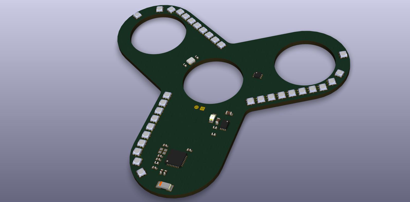
06/09/2017 at 14:29 • 0 commentsNow that I wrote up everything I did earlier today, here is the current status:
![]()
As you can see, the PCB outline is already done and I placed all LEDs, the optical sensor (upper left wing), the ESP8285 and supporting parts (bottom) and the LiPo charger.
I will now upload my current KiCad files to Github.
-
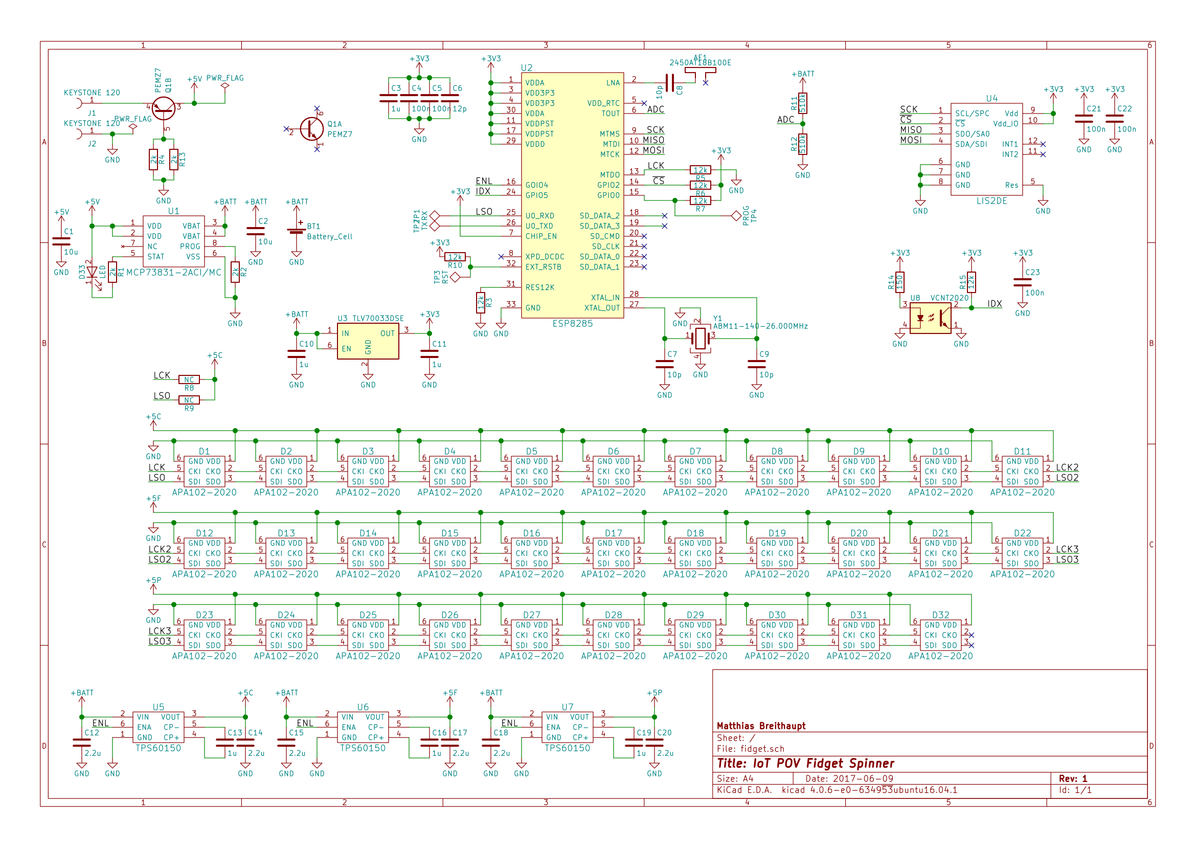
Schematic
06/09/2017 at 14:19 • 1 commentThe schematic is already done. It is attached to this project as a PDF file. You can also find it here:
![]()
I release this schematic as CC BY-SA 4.0.
In the top left corner, you find the LiPo circuitry. The cell can be charged by a MCP73831. This is an IC, I used previously. It works very well in cases like this.
The 3-4.2V from the LiPo go through a TLV70033 LDO to power everything except for the LEDs. The LEDs are in two strings of 11 and (due to space restrictions) one of 10. These are each powered by a TPS60150 (at the bottom). Since this chip can only provide 140mA, the LEDs should be driven with only half the maximum brightness or less. Since there are a lot of LEDs in a small area, that should still be plenty. I don't want to blind the user!
In the top center, you find the ESP8285. The LEDs are connected to the I2S pins, the battery voltage can be measured using a voltage divider (R11 and R12). The HSPI port is connected to the accelerometer, which you find on the top right. Last but not least, there is a VCNT2020 optical sensor. I intend to use this to get an index signal.
This index signal will allow both the proper operation of the POV display, but also gives me the ability to measure the time per revolution. Due to this, the users will be able to compare how fast they can spin their device.
IoT POV Fidget Spinner
A WiFi fidget spinner, taken from concept to ordering parts in one weekend