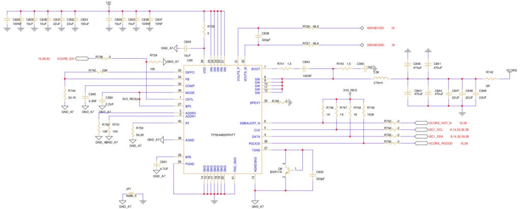
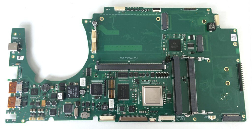
The laptop prototypes testing is progressing great. We tested the primary power supply stage of the CPU, one the most power hungry components in the board, and it is being fine-tuned thanks to a programming apparatus. The chip in charge to power up the CPU NXP T2080 is the Texas Instruments TPS544B20RVFT (Switching Voltage Regulators 4.5-18V 20A SWIFT) as explained at page 37 in our electrical schematics.

The start-up ramp needs to be carefully calibrated, a complex integrated circuit with a some logic that needs to be programmed to make it work properly (i.e. ramps, voltage thresholds, internal ways of making the PWM regulator work, and so on).
The other power supplies are a half a dozen voltage regulators and are meant to power elements such as the PCIe, the RAM, the internal peripheral buses, the connected devices, the Non-Volatile Memory Express (NVMe) and the clock generators the are essential to make the board work properly. The Eclipse Legacy Battery was tested and is recharging properly.
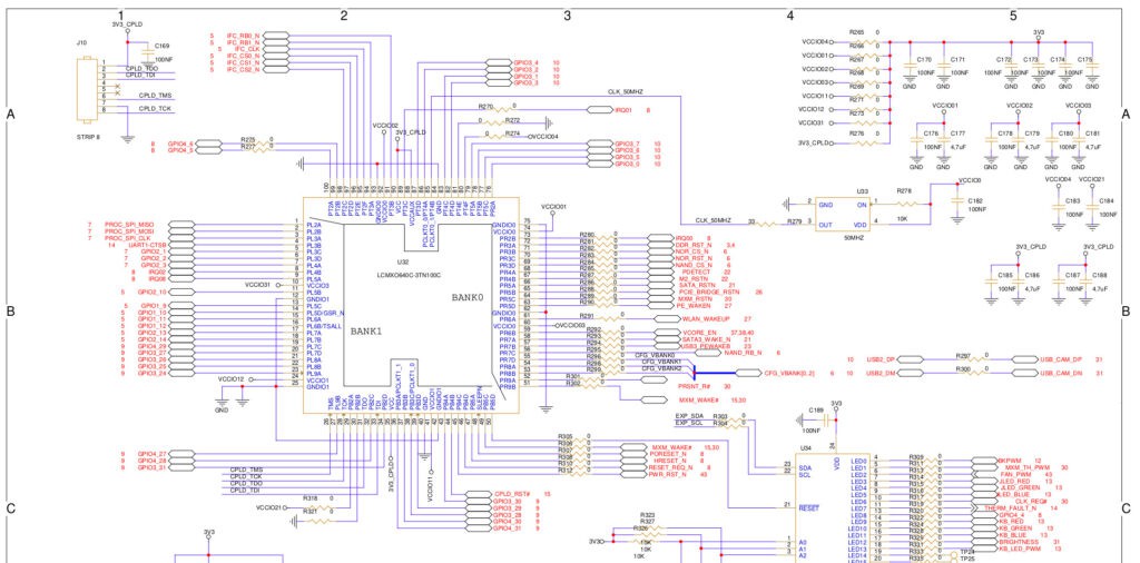
The Complex Programmable Logic Device (CPLD) is a Lattice LCMXO640C-3TN100C FPGA and has to be programmed to manage all those external peripherals connected to it (see the block diagram and wiring diagram on page 15 ), manage interrupts, data, boot reads, set resources according to the CPU and reset all peripherals.

So far so good, the electronic design seems to work correctly, at the moment we are only fine-tuning each electronic component. If all checks continues like this, we might end all electronic debugging in the next few weeks and we can consider this very delicate phase successfully completed. After that, we plan to place the first code in the CPLD, and right after that we should be ready to load U-Boot, the first-stage and second-stage bootloader. We are trying to re-patch a recent version of U-Boot, quite some time has passed since we patched it to make it recognizing the graphic board we mounted on the PCIe port on the NXP T2080RDB board. Not just that, we must carefully customize the device tree to correctly map all peripherals available on the motherboard.
If for it concern the electronical components we can safely rely on the (paid) support of an expert engineer, for setting up U-Boot it’s up to us to make it work properly, and more importantly, to make it correctly recognize all peripherals, especially the SD card, the FLASH and, even more importantly, the two DDR3L RAM slots.

We would like to thank everyone for the continuous flow of donations, and please, continue to do so. At the moment we still need funding to cover the extra costs we faced for the simply crazy prices we paid for the electronical components mounted on the prototypes motherboards and especially for getting our hands on two MXM graphic boards based on AMD chips. For two MXM AMD E9174 video cards with 4GB RAM we have spent 780 dollars ( 360 each) and 185 euro of import Tax around 965 euro .Considering all chips, the cost of each prototype resulted 1200 euros higher than what was initially planned 4392 euros more (1200 x 3 + 22% VAT). So we need to collect around 5357 euro more than the goal of the last donation campaign.
Donations and professional for u-boot
In addition, after an initial round of experiments, we are still struggling to successfully customize U-Boot and to properly setup the device tree. Most of us already spent quite some time on the task during our spare time (remember, we are all volunteers with a proper day job and a personal life ;), so we are seriously evaluating to assign the job to a professional to get the job done in a reasonable amount of time, and to do that we need your financial support!
More Info Roberto Innocenti
Discussions
Become a Hackaday.io Member
Create an account to leave a comment. Already have an account? Log In.