Close
0%
0%

OSHW GNU/Linux PowerPC Notebook

Open Source Hardware GNU/Linux PowerPC Notebook project

Similar projects worth following
The Open Hardware GNU/Linux PowerPC notebook project want to group passionate people like you. These people with their involvement will make the difference to design a new open source PowerPC notebook motherboard

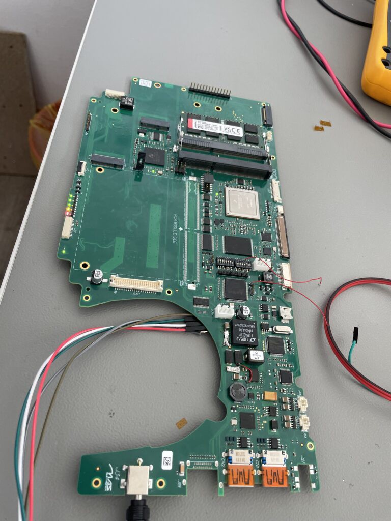
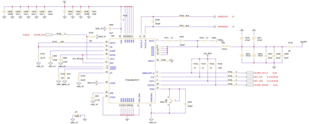
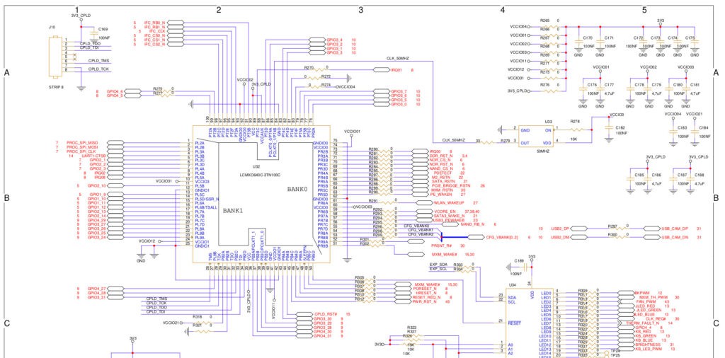
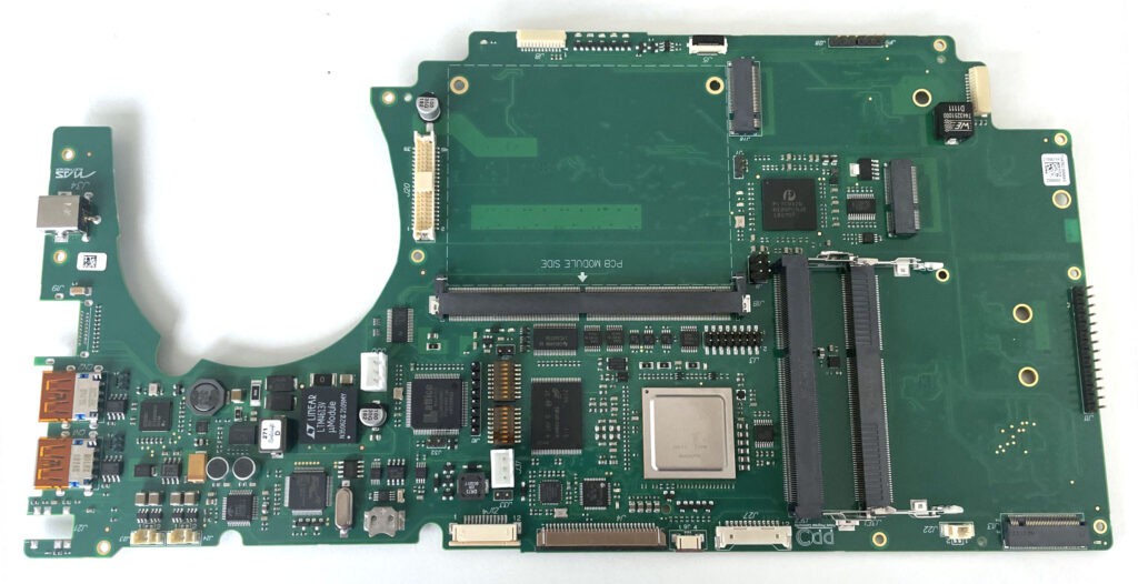
We are in the process of building an ethical purchasing group aimed at commissioning a notebook based on the PowerPC platform. The design is Open Hardware with CERN license 1.2, and the notebook will support Linux natively.

The choice of a small and local producer for making this notebook is both an ethical and forced choice, as on the Italian territory it was the only PowerPC experienced company matching our criteria based on the paradigms of an economy based on the human beings and not on a pure financial gain. We strongly feels that where you can find passion and cooperation making money is not the reference value, and for the selected company it is enough to gain just a little margin, solely aimed at maintaining the company running.

The community that is shaping around this project is much more than a classical ethical purchasing group as, in addition to collecting the necessary funding for producing the notebook, is actively contributing to making possible that GNU/Linux and other operating systems will be fully supported.

The choice of the PowerPC platform is justified by an interesting technological situation: PowerPC CPUs that are produced today have good computational power with regards to the power consumption, they are well supported by the Linux kernel, and many Linux distribution supports the PowerPC architecture. The biggest challenge is a total lack of visibility, as the biggest information technology firms do not use PowerPC in their mainstream products, resulting in the general public completely ignoring their existence. Just count the number of companies, association and groups dealing with the -now mainstream- ARM platform: there is way too much competition in this field, and surely there is no need for new supporters.

Our community is aimed at advertising the notebook project in order to build a group enough big to be able to actually realize the project.

Forum: http://forum.powerpc-notebook.org/ Questionnaire: http://survey.powerpc-notebook.org/ Wiki http://wiki.powerprogress.org/

Social media: https://twitter.com/powerpcnotebook https://www.facebook.com/powerpcnotebook/ https://www.linkedin.com/groups/7300932 

We are building a vast group spread over the 5 continents, a group of creative people having a very heterogeneous background and knowledge and that is willing to collaborate for a common goal: designing and building a notebook  following the Open Hardware philosophy. This is a courageous project, some say a little bit crazy, a project that little or nothing has to share with strict market principles followed by mainstream firms.

Having people spread in the world collaborating on a voluntary basis was made possible by a shared vision: everyone can contribute its own knowledge and competence, share views and experience with others to reach the goal of building a notebook perfectly suiting IT enthusiasts that see in the Open Hardware a viable path for innovating. Altogether we learn the pleasure of discovering al technological aspects that are precluded to the general public when buying a ready-made off-the-shelf notebook, and discovering at the same time the pleasure of sharing such experience and pushing for a virtuous behavior that has generosity at its core.

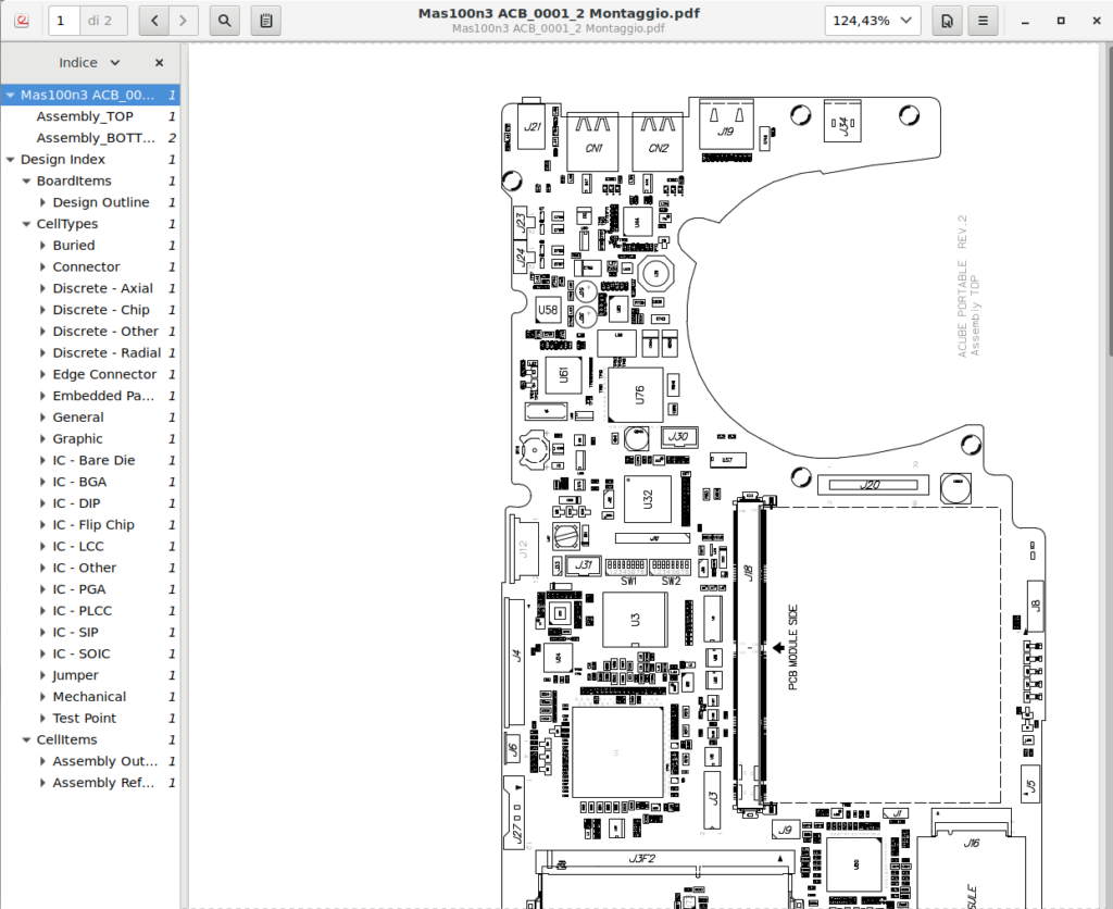
In the community there are people taking care of carefully...

Read more »

PPC_notebook_electrical_schematics_v0.6.DSN

Orcad Schematics Source of PowerPC Notebook - version August 2020 - used for PCB design

dsn - 6.81 MB - 09/30/2020 at 10:33

Download

PPC_notebook_electrical_schematics_v0.6.pdf

Eletrical Schematics of Open Hardware PowerPC Notebook motherboard - version August 2020 - used for PCB design

Adobe Portable Document Format - 3.56 MB - 09/30/2020 at 10:32

Preview

PPC_notebook_electrical_schematics_v0.5.pdf

Eletrical Schematics of Open Hardware PowerPC Notebook motherboard - version June 2020

Adobe Portable Document Format - 13.03 MB - 07/19/2020 at 11:50

Preview

PPC_notebook_electrical_schematics_v0.4.pdf

Eletrical Schematics of Open Hardware PowerPC Notebook motherboard - version May 2020

Adobe Portable Document Format - 12.98 MB - 05/25/2020 at 20:46

Preview

ppc_bloc_diagram_05_04_2020.png

block Diagram April 2020

Portable Network Graphics (PNG) - 1.36 MB - 04/08/2020 at 22:13

Preview

View all 11 files

  • 1 × CPU NXP T2080 QorIQ® T2080 Multicore Communications Processors - Power Architecture
  • 1 × Marvell SATA3 88se9235 Controller
  • 1 × Renesas μPD720201 USB3 Controller
  • 1 × Pericom PCIe Packet Switch PI7C9X2G612GP 6-port, 8-lane, PCIe2 Packet Switch with GreenPacket Technology
  • 1 × MicroChip USB2514 USB 2.0 hub controllers

View all 6 components

  • First PCB Desktop Layout!

    Roberto Innocenti12/25/2025 at 21:36 0 comments

    Today we publish here ( above) an export from PCB design of our PowerPC Desktop motherboard (based on processor NXP T2080) , you can see the motherboard top view with components and connectors, it reflect the progress on pcb design, that is going fast. Before the end of January will be completed !! In January should be defined the costs and timing for the production of the prototypes.

    • The dispositions of components on the board are not final.
    • As requested by our association members there are 4 holes 30-42-60-80 for the left M.2 connector.
    • The two Ethernet are one on top of the other.
    • There is even a digital audio output.
    • There are 3 PCIE connectors: 16x, 4x Open ( with space for 8x and 16x), 1x

    In the mean time that is in progress the donation campaign for the schematics design we open now the donation campaign for the PCB design.

    Payments we should do next days:

    Schematics Design

    Before 31 December we should balance the payment for the schematics design plus 850 euro needed to fill the review questionnaire asked by NXP, So we have summed the 850 euro to the running campaign for the Schematics.

    PCB Design

    We need to pay at beginning of January the 50% of the cost for PCB design that is around 6100 euro, so we have created the PCB design campaign that is 12500 euro ( 10000+VAT+paypal/stripe fees) .

    TO DONATE


    We thanks donors and collaborators that permit us to finance everything realized until now.

    We are going faster as promised, to realize a working Open Hardware PowerPC motherboard in few months , that increase rhythms of design and production, costs and ask us to increase even the rhythm of donations…

    Donation is a form of collaboration so apart your one shot or recurrent donation that are welcome, we even ask you to spread all over you can our project so more potential collaborators could join our project.


    On 12th December NXP confirm us that the review of our source schematics was submitted, they don’t give us any estimation on how much time they take to do the revision and to give us the permission to publish as Open Hardware the schematics source. After we will have the agreement from NXP we will publish the sources as we do usually, as we have done for our Powerboard Tyche Notebook motherboard sources.


    Debian 13 installer for PPC64 and powerpc (32bit)

    We are very happy that Debian ports team have published a working Debian 13 installer for PPC64 and powerpc so we have tested on PowerBook G4 and IMac G5. Please join us if you want to help on test Debian PPC64 package or if you want to test even Mint PPC


    We have published on our forum how to install it.

    More info


  • PCB Design Costs and Timing

    Roberto Innocenti12/22/2025 at 22:34 0 comments

    PCB Design Costs and Timing

    In our last post we have announced that we were reviewing the schematics of our Powerboard Tyche Desktop; this careful process involved ACube Systems and one hardware engineer from our team from mid-October to mid-November. So on 10th November we sent our schematics to the PCB design company for quote, that resulted to be around 12500 euros (VAT included). In the next ten days ACube Systems, our actual designer and the PCB design Company will meet to refine every detail like the ATX board dimensions, PCB layers, that should be ten layers.

    Schematics Sources Publication

    Our hardware designer completed to fill the NXP questionnaire to ease NXP review of Powerboard Tyche Desktop source, so we have forwarded to NXP everything they requested us to allow publishing the parts of our board derived from NXP T2080 RDB Revision F. We asked NXP how much time the review will take, but we don’t have an answer so far. Stay tuned!

    After NXP green light we will publish the Powerboard Tyche Desktop schematics on GitLab as usual. Since designer and NXP use Cadence ORCAD, we will convert our motherboard sources to Altium and then KiCad.

    Steps before Production

    We expect that the PCB design will be completed beginning of February 2026, thus we strongly need donations to pay for the PCB design.

    After that, prototypes production could be set up, so signing the manufacturing agreement depends on your donations and on your activity to spread the word about our project and donation campaigns to the world.

    If donations keep steady, we then expect to have prototypes in a couple of months (April 2026) so that we can afterward perform hardware tests. If everything goes according to the plan, in June 2026 the hardware test will be successfully completed and we will see booting with Debian PowerPC64 and other GNU/Linux distribution as we are doing with our T2080RDB devkit converted in Desktop from 2016.

    Powerboard Tyche Desktop and Notebook

    Therefore, we expect ACube System to start boards pre-orders in July 2026 and, in the mean time, we will go back to work on the next milestone for the notebook version: please join our notebook work group if you want!

    Join the Software Workgroup for PPC64BE

    We invite anyone to support GNU/Linux PowerPC distribution like Debian to improve support on PPC64 big endian architecture.

    contact us

    Spread the Word

    You can take part to the project success by talking about it in the fediverse or in any kind of forum, blog, website, etc… you think it would be relevant on!

    DONATE

    Linux Day Milano and SFSCON

    As usual our volunteers were ambassadors at Free Software events as we have done in the past on Freeplanet event, FOSDEM 2020, Open Power Summit Open Source Summit, etc…. : this fall we participated at Linux Day Milano on October 25th and SFSCON on 6th-7th November, and as usual we got to involve some more people in our activities!

    Sfscon – Bolzano – 7th November 2025 – speech Open Hardware PowerPC Powerboard Tyche Desktop

    We want to underline the meaning of our open hardware projects

    We have vehicles, appliances, phones that cannot be fixed, because their manuals are not available, they are locked behind DRM, or spare parts are either unavailable or prohibitively expensive. Even more worrisomely, perfectly fine connected devices become useless bricks just because the original manufacturer do not find them profitable anymore. This creates unbelievable amounts of unnecessary waste.

    Nowadays, we see laptops with soldered RAM and GPU, absolutely closed design and mostly running closed OSs. Our design that started in 2017 has 2 RAM slots and a separated MXM video card.

    Powerboard Tyche Notebook – MXM video card slot and 2 RAM slot

    Our notebook motherboard design fits in an already produced notebook shell and uses a PowerPC processor that can keep up with modern mid-end boards, even though its production started in 2012: a true testament of a good design.

    In 2006 we have seen...

    Read more »

  • Schematics of the Powerboard Tyche Desktop version Completed! Soon starting the PCB design

    Roberto Innocenti10/30/2025 at 23:17 0 comments


    We now have the complete electronic source design for our new desktop design in our hands!

    This week, ACube Systems and some volunteers from our association will review the design. We expect the manufacturer to start setting up the PCB layout for the new Powerboard Tyche Desktop on October 20th. This is part of our strategy to focus on creating a stable, functional desktop version of the core computing platform by the end of 2025.

    The PCB design phase (Phase 2) will begin shortly after the schematics and Bill of Materials (BOM) are sent to the manufacturer. We anticipate that this step will allow the manufacturer to provide us with an estimate of the cost and timeline for the PCB layout design. This cost and timing estimate will then be shared with the community “just in time.”

    Technical Components and NXP Review

    We have verified that the availability of SATA2/3 controllers is poor, and the chip Lattice Silicon Image SiI3132 chip that we selected is no exception. We decided to include it in our desktop board to ensure backward compatibility with SATA devices, such as DVD and HDD.

    We do not use the on-chip T2080 SATA2 controller because we prefer to use the T2080’s three x4 PCIe Gen3 configuration to optimize the speed of video cards and storage controllers. This configuration cannot coexist with the on-chip SATA2. In any case, the best performance is possible thanks to our M2 motherboard interfaces.

    In our board design, we have an SPI connection for an external LCD, which can be used as a secondary screen or for debugging and diagnostics. It is also useful when setting up u-boot and when no video card is connected to the board.

    Our board design includes GPIO connectors that can be used to connect other devices that don’t use USB, SPI, or PCIe buses.

    Our desktop design is derived from our old notebook design and the original NXP T2080 RDB (Release F) design. We are integrating many components specified in the reference board, including critical monitoring hardware.

    This includes the OnSemi ADT7481ARMZ thermal monitor, which has been upgraded to the OnSemi NCT72. The ADT7481 is used as the thermal monitor or temperature sensor on the original NXP T2080 reference design board. On that board, the ADT7481 (designated U34) is usually connected via the I2C_1 bus with the address 0x40. The T2080 processor itself contains a temperature diode designed to be used with system temperature monitoring devices, such as the Analog Devices ADT7461A. This similar part is mentioned in the documentation for the T1042 chip, which highlights the standard use of such monitoring.

    Designers have changed other components from the original T2080 RDB design and our notebook design due to the availability of new compatible models, such as the N25Q512A13 FLASH SPI, which is substituted for the EvKit Micron MT25QL512A due to its limited availability.

    Due to the changes in components, we will need to modify the VHDL code of the CPLD chip when we have the prototypes in our hands. Therefore, we must take into account the additional cost of this task.

    To ensure full compliance and open-source publication readiness,

  • The designer will fill out the NXP review questionnaire [draft post 2025-10-12] simultaneously.
  • The questionnaire and the Cadence schematic source will then be sent to NXP.
  • The main goal is to receive a full or partial agreement to publish the parts of our design derived from the original NXP T2080 RDB (Release F) as open hardware
  • We anticipate a robust boot-up because the components and firmware are similar to those of the stable T2080 RDB. The specific CPLD is programmed using the original CPLD source code of the T2080 RDB. Once NXP grants the necessary agreement, we plan to publish the source schematics and evaluate the use of a recent CERN Open Hardware License version.

    Upcoming Project Phases

    The next anticipated milestones, pending finalization of cost estimation:

    • Phase 2: PCB design. (tentatively scheduled two months after...
    Read more »

  • Desktop Electrical Schematics Ready! in August.25

    Roberto Innocenti07/16/2025 at 17:24 0 comments

    We are very happy to inform you that the Schematics Design of our new Powerboard Tyche Desktop is running fast thanks to the new Designer and to the NXP Devkit source design plus our Powerboard Tyche Notebook design. Designer took from the NXP Devkit design ( 2023 version) everything is related to the boot process and many parts from our Notebook design, except what is not needed for the Desktop version, like the Battery part.

    You can check all the details regarding what we took from Devkit design and what we took from our Powerboard Tyche Notebook design.

    At the end of July, we will provide the schematic design and the BOM to the factory, which will then begin the PCB design based on the schematics. Therefore, by the beginning of August (before the factory’s holiday closure), we will know the cost for the PCB design and prototype production. New donation campaigns will then start for PCB design and prototype production.

    Today, July 14th, 2025, we’ve officially launched the donation campaign for the schematics. Before the end of July, we’ll make the down payment for the schematics design. We already have funds collected from the previous donation campaign for the CE certification (of the Powerboard Tyche Notebook), so we can advance money from that fund. However, it’s crucial to boost this new campaign and encourage everyone to donate so we can use fresh funds specifically for the schematics design.

    SPECS

    • Form Facttor: Micro ATX
    • CPU: NXP T2080, e6500 64-bit Power Architecture with Altivec technology
      • 4 x e6500 dual-threaded cores, low-latency backside 2MB L2 cache, 16GFLOPS x core
    • RAM: 2 x DDR3 Slots
    • VIDEO
      • PCIE3 x16 VIDEO Card 1
      • PCIE2 x4 VIDEO Card 2
    • AUDIO: C-Media 8828 sound chip, audio IN and audio OUT jacks
    • USB: 3.0 and 2.0 ports
    • STORAGE:
    • NETWORK:
      • 2 x Gigabit ethernet RJ-45 connecto

    Yes, it’s possible to reach the goal to have a working Powerboard Tyche Desktop before the end of 2025, but is needed an extraordinary effort from donors because we depend on donations to cover all the steps that are coming : Schematics Design, PCB Design, Prototype Production and Tests.

    Starting from today (July 14th 2025) you can make your donation, thanks!

    Milestones

    Phase 1: Actual Campaign Schematics Design : goal 30.07.2025

    Phase 2: PCB Design : goal 30.09.2025 [depending on donations collected]

    Phase 3: Prototypes Production: goal  30.10.2025 [depending on donations collected]

    Phase 4: Prototypes Tests. : goal  30.11.2025 [depending on donations collected]

    The milestone phases depend from your donation. Thanks!

    We remain absolutely committed to making an Open-Hardware Notebook-based PowerPC machine a reality.

    As we have already published on our past post we have changed the tactic, focusing on a desktop board first allows us to concentrate on getting the core computing platform stable and functional, tackling the complexities of a laptop form factor (like power management, screen integration, etc.) in a later stage if needed. This is a pragmatic step to ensure we achieve a tangible outcome by our 2025 target. What’s more the Powerboard Tyche Desktop version will be more cheaper than the Notebook version!

    We value the experience of making our Open Hardware Powerboard Tyche based on PowerPC from scratch; this is possible thanks to the support of all donors and supporters, and the time and creativity of the activists who have been involved in this project over the years.

    We ask you to share every-ware this call for support a strong flow of donations to cross the finish line of all donation campaigns to arrive by 2025 with produced, tested and functioning prototypes!

    TO DONATE

  • Strategic Change: By 2025, let’s do whatever It Takes to achieve at Least a desktop version!

    Roberto Innocenti05/21/2025 at 21:34 0 comments

    Hello everyone, we know it’s been quite some time since our last update on November 21, 2024.

    We really appreciate your patience! Despite the silence on our end, we’ve seen that our incredible community – both old friends and new supporters – have continued to donate continuously. An infinite thanks to all of you, our amazing current, past, and future donors! Your unwavering support truly fuels our efforts and keeps the dream alive.

    Image by Tú Anh from Pixabay

    Short story

    As we shared in our last post, the work with the previous designer hit a significant hurdle: we just couldn’t get the board to reach the crucial boot stage.

    This led us on a search for a new designer, someone with specific skills and experience with PowerPC architecture. We were really pleased to find a talented new designer who was available from the beginning of 2025, who can even rely on an additional person who is an expert in firmware programming. Following our plan, we used January and February to make the big move, getting all the equipment transferred over to this new designer’s team.

    We held off on publishing updates because, honestly, we were waiting for that breakthrough moment – the good news we could finally share with all of you. As things were showing quite promising (e.g. improved CPU signals outputs), we had high hopes that this new collaboration would quickly move us past the booting issues. In parallel, we also tried improving U-Boot and led an additional T2080RDB, the development board that was kindly provided by NXP, to one of our collaborators, but due to personal health problems, he can no longer contribute to the project.

    Our work with the new designer has been focused on rigorous testing. On April 9th, we saw that the board’s behavior was frustratingly similar to the devkit – it still wasn’t booting. This prompted a dedicated session on April 14th for one last intensive attempt to find the root cause. As part of this deep dive, we de-soldered the Marvell chip, which is the SATA3 controller.

    Removing this component was actually something we had already planned to do for the upcoming prototype version as we streamline the design. To help isolate the issue even further, we also de-soldered the Pericom chip.

    The overall outcome? Despite taking these significant steps, the board still did not boot. It exhibited exactly the same behavior. We were, frankly, quite upset and left without words.

    It’s incredibly challenging when you put in the effort, try to simplify things, and the core problem persists. So far, we have spent around 6000 Euros with the newly hired hardware designer, and even if things have improved, showing the expected NXP documented behaviors of the NXP reference development board, after two years with the prototype motherboards in our hands, we still are not able to boot it.

    So what’s next?

    This difficult moment, however, has reinforced our resolve and led to a strategic adjustment, as the title suggests. We remain absolutely committed to making an Open-Hardware Notebook-based PowerPC machine a reality.

    By the end of 2025, we are determined to do whatever it takes to have at least a stripped-down functional desktop version of our Powerboard Tyche up and running.

    We change tactics

    Focusing on a desktop board first allows us to concentrate on getting the core computing platform stable and functional, tackling the complexities of a laptop form factor (like power management, screen integration, etc.) in a later stage if needed. We even plan to revert to the NXP original CPLD used in their development board, not the version we previously selected for the notebook prototypes. This is a pragmatic step to ensure we achieve a tangible outcome by our 2025 target.

    The path forward still has its challenges. We need to understand precisely why the notebook prototype board isn’t booting and what electronic redesign might be required, and for this, we are in contact with experts directly at NXP....

    Read more »

  • Major improvements for Powerboard Tyche despite adversity, but there is still work to be done

    Roberto Innocenti11/28/2024 at 13:59 0 comments

    Photo by mohamed_hassan from PxHere

    The hardware designer who created our Powerboard Tyche worked between April and July on one of the three prototypes, focusing on fixing the board firmware. These fixes required a series of checks to determine if any additional adjustments were needed for the board itself, and a complete analysis of electronic signals was performed. This analysis was provided later in September. The same fixes were applied to the second prototype (we have three prototypes).

    u-boot 2018.11 enabled AMD video cards

    Additionally, Max Tretene from ACube Systems was hard at work on our NXP T2080-based DevKit and completed a newer version of U-Boot in May, which finally enabled graphical output on AMD Radeon video cards during booting. You can find the updated source code on our GitLab. Below you can see the new U-Boot in action booting up the NXP T2080-based DevKit.

    Below is a photo showing the Powerboard Tyche during an electronic test session conducted last August.

    In August, the hardware designer sent back two prototypes to our firmware engineer. ACube Systems purchased an oscilloscope to continue analyzing signals on the prototypes, since the oscilloscope previously used by the firmware engineer was on loan.

    In September, signal analysis using the oscilloscopes began, comparing the NXP T2080-based DevKit and our Powerboard Tyche to identify differences. Many differences were found in the power-up sequences, so we asked the hardware designer to fix the CPLD program responsible for governing the signals.

    Below is a picture of the expected power-up signals as explained in the T2080 Manual.

    Below is picture showing the signals from the Powerboard Tyche last August, a picture extracted from the Test Report provided by the hardware designer.

    As you can see above there is some difference of PORESET_B and HRESET_B between what was found during the hardware tests on pur board and what is expected in the NXP manuals.

    In September, a new series of tests were performed. Below are two pictures from the oscilloscope showing the output of different attempts while reprogramming the CPLD of the Powerboard Tyche.

    As we can see on the screenshot even the tension of 2,51 volt was wrong, as it should be not more than 2 volt.

    During September and October, there were many reprogramming cycles of the CPLD. Each time, the hardware designer recompiled the HDL of our CPLD and sent it to our firmware engineer, who had two prototypes in hand. Reprogramming the prototypes was quite slow, as neither the hardware designer nor the firmware engineer were working full-time in our project. We sent one prototype back to the hardware designer, and by the end of October, he had completed the CPLD updates. At the end of this hard work the CPLD finally generates the expected power-up signals, reproducing the same signals generated during power-up of the NXP T2080-based DevKit.

    The final version of the CPLD firmware (published on GitLab) modifies the behavior of the two signals PORESET (yellow) and HRESET. Indeed, the oscilloscope shows that the two signals now behave differently compared to previous versions.

    By the end of October, the signals on the Powerboard Tyche finally looked correct (picture below)

    As you can see the now the tension is correct, around 1,95v, in August was 2,51v

    Unfortunately, the changes to the CPLD did not resolve the boot-up process of the entire board.

    Strangely enough, during tests we found differences in the power-up behavior between two of the prototype boards: one in the hands of the firmware engineer (FE) and the other in the hands of the hardware designer (HE). Here are the three differences we found:

    • On the HE board, the ASLEEP LED stays off if the SD card with U-Boot is inserted and lights up if it is not inserted.
    • On the FE board, the ASLEEP LED always stays on, regardless of whether an SD card is inserted or not.
    • On the HE board, the oscilloscope shows activity...
    Read more »

  • fine tuning firmware for u-boot and develop Radeon driver for latest u-boot version

    Roberto Innocenti11/18/2023 at 18:12 0 comments

    it’s a quite some time has passed since the beginning of July when we posted about the start-up ramp that carefully calibrated, programming a complex integrated circuit with some logic (i.e. ramps, voltage thresholds, internal ways of making the PWM regulator work, and so on) and when the Complex Programmable Logic Device (CPLD) (Lattice LCMXO640C-3TN100C FPGA) was programmed for the very first time in order to manage all external peripherals connected to it.

    In July we figured out  that a Jtag Debugger was very needed to debug our Powerboard Tyche, the only way to solve the causes of not seeing any U-Boot output. We were able to buy such a debugger thanks to the donations we are collecting with the  current campaign, we thank all donors for their support.

    The debugger is  the NXP CWH-CTP-BASE-HE Jtag Debugger + NXP CWH-CTP-COP-YE “Probe Tip, Removable, For Power Architecture Processors, JTAG to CodeWarrior TAP Base Unit” and, together with one of the three prototypes, we shipped it in August to Max Tretene that kindly accepted to be directly involved in the debug process of the motherboard. Soon, the task proved to be quite challenging, so after an internal discussion, we decided to  offer Max a reimbursement for all the time he was spending on the job, a reimbursement that was made possible to the donations we are receiving with the current campaign.

    Dealing with hardware debugging is quite a hard and tedious job, and it was not easy to see something useful on the Jtag Debugger connected to the prototype motherboard. An additional adapter was required to attach the debugger because of the difference in the pin dimensions (2 vs 2.5). Max found it quite useful using the jtag debugger with our NXP T2080-RDB Devkit that was also shipped to him, because it allowed to test the procedure on a working platform and helped understanding the right configurations of the switches to boot up the board.

    As our PowerBoard Tyche have not the third switch like the NXP T2080-RDB Devkit a few additional resistors were required to setup correctly the board to be able to switch on the Code Warrior debug connected to our Powerboard Tyche. Not just that, an additional update to the CPLD chip was required to setup the debugging system correctly. Finally, on the 16 of October, Max was able to see some sign of life from the NXP T2080 CPU on SRAM and on NAND Memory, as you can see in the screenshots below. These days we are working on NOR programming, waiting in the meantime for a CPLD update from the hardware designer. The NOR programming is needed to have access to the DDR and then start U-Boot.

    SRAM programming – CodeWarrior® Development Suites for Networked Applications attached to Powerboard Tyche
    SRAM programming – CodeWarrior® Development Suites for Networked Applications attached to Powerboard Tyche
    NAND Programming – CodeWarrior® Development Suites for Networked Applications attached to Powerboard Tyche
    NAND Programming – CodeWarrior® Development Suites for Networked Applications attached to Powerboard Tyche

    Some possible changes to the hardware design

    All these hardware tests were useful for planning some changes to the hardware design: few missing resistors for enabling the u-boot switches must be added and we need to move one chip because it does not fit quite right in the eclipse chassis.

    The recent worldwide electronic components shortages we faced when making  the prototype Powerboard Tyche boards caused an unexpected -and incredible-  increase of the prices. More recently chip prices seem to be coming back to more reasonable prices, with the exception of the Marvell Sata3 controller.

    As a consequence, we are evaluating the removal of the Marvell Sata3 controller to both free very-much needed space space and save some costs because at the moment such a chip costs around 90 euros per piece, quite a lot.

    In fact, nowadays most SSD are available at a very good price with the M.2 form factor, so a Sata3 connection is not that essential anymore. People in a desperate need for a Sata connection could use the two Sata2 controllers inside the T2080 CPU.


    Below we list the availability and prices...

    Read more »

  • Working on u-boot even with jtag debbuger and redesign of heat pipes

    Roberto Innocenti07/02/2023 at 12:36 0 comments

    Once again we want to thank you all for the great support and great enthusiasm you demonstrated during the CE mark donation campaign. We ended the campaign with a total amount of 12500€ (https://en.wikipedia.org/wiki/CE_marking), this is a huge milestone for us all and we are so very grateful.

    By financing the CE mark certification you have shown us that you believe in the project and our vision of creating a fully open hardware notebook motherboard based on the alternative PowerPC CPU architecture.

    We closed the campaign with around € 4000 more than expected, and this extra money will cover some of the extra and unplanned costs we faced for the increased price of electronic components and the extra costs of the three MXM video cards (360 USD each).

    The CE mark certification is a mandatory requirement for selling electronic products in the European Union. It ensures that our notebook motherboard meets the safety, health and environmental standards of the EU. Without it, ACube Systems would not be able to launch and sell our Notebook on the EU market. Getting the CE mark certification is not an easy nor a cheap process as it involves rigorous testing, documentation and quality controls.

    However, the CE certification process can be performed only when the product can be considered completely finished, and that means once the board works, the cooling metal pipes are in place and all is assembled into the selected slimbook eclipse chassis.

    Current activities

    The Tyche Motherboard has surpassed all the electrical checks, and now the the key activities being performed concentrate on the hardware initialization procedures.

    The start-up ramp was carefully calibrated, programming a complex integrated circuit with some logic (i.e. ramps, voltage thresholds, internal ways of making the PWM regulator work, and so on).

    The Complex Programmable Logic Device (CPLD) is a Lattice LCMXO640C-3TN100C FPGA is programmed to manage all external peripherals connected to it (see the block diagram and wiring diagram on page 15), manage the interrupts, data, boot reads, set resources according to the CPU and is able to reset all peripherals.

    Working on U-Boot

    Currently, a small team of volunteers are working on U-Boot . We are decided to buy a JTAG debugger, a quite useful tool indeed that will make the hardware debugging much easier.

    We learnt how to configure and build U-Boot, and we set up a cross-development PowerPC toolchain and the related Device Tree Blob that is used to describe the physical configuration of each hardware component available on the motherboard. You may keep an eye on our attempts by looking at our GitLab pages. We started by re-compiling our old U-Boot binary dating back to 2019, the one that we are currently using on our NXP T2080RDB devkit and also trying to compile a newer U-Boot version from a the DENX mainline vanilla branch without our patches. We are now kindly assisted by Max Tretene, the same guy working at ACube Systems that compiles U-Boot for their motherboards such as the Sam440 or the Sam460ex. Max is currently available to introduce hardware support to AMD/ATI Radeon graphics cards in U-Boot, (ndr.: he recently told us that his spare times is not enough so we are proposing him to work under payment) stay tuned for more in-depth posts about it. In the hope of speeding up the development, we provided Max Tretene with our NXP T2080RDB devkit in early June.

    We want to thank the dedicated small group of volunteers and especially Max Tretene for their precious spare time spent in trying to configure and compile U-Boot, we very much appreciate their availability and effort, even if a successful result is yet to comes. In addition, we greatly appreciated the offer made by a professional engineer – not to be disclosed yet- that is ready to work for us on U-Boot for a very reasonable amount of money.

    Launch of a new fundraising campaign

    After quite some internal discussion, we finally...

    Read more »

  • Prototypes testing results

    Roberto Innocenti02/28/2023 at 09:52 0 comments

    The laptop prototypes testing is progressing great. We tested the primary power supply stage of the CPU, one the most power hungry components in the board, and it is being fine-tuned thanks to a programming apparatus. The chip in charge to power up the CPU NXP T2080 is the Texas Instruments TPS544B20RVFT (Switching Voltage Regulators 4.5-18V 20A SWIFT) as explained at page 37 in our electrical schematics.

    The start-up ramp needs to be carefully calibrated, a complex integrated circuit with a some logic that needs to be programmed to make it work properly (i.e. ramps, voltage thresholds, internal ways of making the PWM regulator work, and so on).

    The other power supplies are a half a dozen voltage regulators and are meant to power elements such as the PCIe, the RAM, the internal peripheral buses, the connected devices, the Non-Volatile Memory Express (NVMe) and the clock generators the are essential to make the board work properly. The Eclipse Legacy Battery was tested and is recharging properly.

    The Complex Programmable Logic Device (CPLD) is a Lattice LCMXO640C-3TN100C FPGA and has to be programmed to manage all those external peripherals connected to it (see the block diagram and wiring diagram on page 15 ), manage interrupts, data, boot reads, set resources according to the CPU and reset all peripherals.

    So far so good, the electronic design seems to work correctly, at the moment we are only fine-tuning each electronic component. If all checks continues like this, we might end all electronic debugging in the next few weeks and we can consider this very delicate phase successfully completed. After that, we plan to place the first code in the CPLD, and right after that we should be ready to load U-Boot, the first-stage and second-stage bootloader. We are trying to re-patch a recent version of U-Boot, quite some time has passed since we patched it to make it recognizing the graphic board we mounted on the PCIe port on the NXP T2080RDB board. Not just that, we must carefully customize the device tree to correctly map all peripherals available on the motherboard.

    If for it concern the electronical components we can safely rely on the (paid) support of an expert engineer, for setting up U-Boot it’s up to us to make it work properly, and more importantly, to make it correctly recognize all peripherals, especially the SD card, the FLASH and, even more importantly, the two DDR3L RAM slots.

    Powerboard Tyche, top side. The visible biggest gray chip is the CPU NXP T2080 Power Architecture CPU.

    We would like to thank everyone for the continuous flow of donations, and please, continue to do so. At the moment we still need funding to cover the extra costs we faced for the simply crazy prices we paid for the electronical components mounted on the prototypes motherboards and especially for getting our hands on two MXM graphic boards based on AMD chips. For two MXM AMD E9174 video cards with 4GB RAM we have spent 780 dollars ( 360 each) and 185 euro of import Tax around 965 euro .Considering all chips, the cost of each prototype resulted 1200 euros higher than what was initially planned 4392 euros more (1200 x 3 + 22% VAT). So we need to collect around 5357 euro more than the goal of the last donation campaign.

    Donations and professional for u-boot

    In addition, after an initial round of experiments, we are still struggling to successfully customize U-Boot and to properly setup the device tree. Most of us already spent quite some time on the task during our spare time (remember, we are all volunteers with a proper day job and a personal life ;), so we are seriously evaluating to assign the job to a professional to get the job done in a reasonable amount of time, and to do that we need your financial support!

    More Info

  • Ready for Prototypes production with reworked PCB design with all available components

    Roberto Innocenti08/29/2022 at 22:41 0 comments

    Published Powerboard Tyche PCB reworked source

    Finally, the reworked PCB design source of Powerboard Tyche with the updated available components is ready ( in older posts you can go more deep about “our” electronic components shortage issues). This work was made using Mentor Expedition and it is ready and uploaded into our repository with all reported issues fixed, including issue number 5, the last one corrected . Thanks to our collaborators we are able to export this work using Altium form so the next days we will publish it and we will try to convert it to Open Source Kicad format ( and probably loosing something in the conversion process) . In our older post we have give more details regarding the PCB sources.

    Inside Output folder you can find many interesting files easy simple viewable like the “the plot separate sheet” CAM350/DFMSTREAM and the Motherboard Assembly TOP and BUTTOM.

    As a conclusion now we have everything to produce and make the hardware tests in September.


    In July we have published more details about the rework design due to the global shortage of electronic components

    Rework of a part of the mobo and situation of the components


    As you know, we were having troubles to find a few components in the marked (listed below) not only because of their availability but also due to the increased price. After an extensive research, the designer was able to identify the replacement components.

    Below, a detailed list of unavailable or extremly expensive parts that the designer is replacing with other readily-available components:

    • 1 per pcb Transistor: NPN; BSR17A bipolar; 40V; 0.2A; 0.35W; SOT23 – ON SEMICONDUCTOR > 3100>#/strong### cost increase from 0,5 euro to 16,50 euro per piece
    • 4 per pcb Field Effect Transistor –NDC7002N MOSFET 2N-CH 50V 0.51A SSOT6 – ON SEMICONDUCTOR : >1100>#/strong### cost increase from 0,50 euro to 6,5 euro per piece
    • 2 per pcb MOSFET N-CH 100V 60A PPAK SO-8 SiR870DP – Vishay Siliconix > 3250>#/strong### cost increase from 1,53 euro to 50 Euro per piece
    • 1 per pcb Parallel NOR Flash Automotive Memory MT28EW01GABA1HJS-0AAT – MICRON > 3250% cost increase from 13 euro to 423 euro!!!
    • 1 per pcb IC EEPROM 256KBIT I2C 1MHZ 8SOIC AT24C256C-SSHL-B – Microchip Technology > 1000>#/strong### cost increase from 0,29 euro to 2,5 euro
    • 1 per pcb 24-bit translating 1.65- to 5.5-V I2C/SMBus I/O expander TCA6424ARGJR – Texas Instruments Not Available
    • 1 per pcb 24 MHz XO (Standard) LVCMOS Oscillator ASFLMB-24.000MHZ-LC-T – Abracon LLC – Not Available
    • 1 per pcb I/O Controller Interface IC HI-PERFORM LW PWR SM FOOT USB 2.0 HUB USB2514-AEZCNot Available
    • 1 per pcb Two-Lane PCIe 2.0 to Four-Port 6 Gbps SATA I/O Controller 88SE9235 – MARVELL – 980 euro!!!!!!!
    • 1 per pcb 6-port, 12-lane, PCIe 2.0 Packet Switch PI7C9X2G612GP – Diodes – 700 euro!!!!
    • 1 per pcb Power Switch ICs FDC6331L – onsemi / Fairchild – >3300>#/strong### cost increase from 1,25 to 41,6 euro
    • 1 per pcb Switching Voltage Regulators 4.5-18V 20A SWIFT TPS544B20RVFT – Texas Instruments – 90 Euro!!!
    • 6 per pcb Switching Voltage Regulators 4.5-V to 28-V, 6-A TPS56637RPAR – Texas Instruments – > 10000>#/strong### cost increase from 3 euro to 344 euro per piece ( 6 piece = 2.064 euro!!!)

    Previously missing in February, but now available again

    • 3 per pcb IRLML6346TRPBF – N-Channel 30 V 3.4A (Ta) 1.3W (Ta) – Infineon Technologies
    • 2 per pcb 403C11A24M00000 24 MHz ±10ppm Crystal 10pF 60 Ohms 4-SMD
    • 7 per pcb MOSFET – DMN3730U-7 N 750mA 30V POWER MOS – Diodes
    • 9 per pcb Trans MOSFET – SI4925DY P-CH 30V 5.3A 8-Pin SOIC – ON SEMICONDUCTOR

    The designer have replaced these components with new ones available currently and having an affordable cost in the market. Consequently, there was an extensive rework of the electrical schematics and of the Printed Circuit Board design.


  • View all 32 project logs

    Enjoy this project?

    Share

    Discussions

    6baindurashvili_3 wrote 08/12/2021 at 12:05 point

    What a great pleasure to read this impressive project details I am also working on a similar type of project you can see here.

      Are you sure? yes | no

    kwapiszon wrote 10/21/2020 at 09:13 point

    how long this device work? for example I can decrease cpu to 40Mhz and working time increase to week on one charging battery?

      Are you sure? yes | no

    Roberto Innocenti wrote 12/19/2020 at 19:40 point

    the T2080 processor itself have Advanced Power and Energy Management as you can see here https://www.nxp.com/files-static/training/doc/ftf/2014/FTF-NET-F0032.pdf we will see the prototypes and Linux how results in terms of battery life

      Are you sure? yes | no

    kwapiszon wrote 02/12/2021 at 13:46 point

    one week will be great. my psion 5 work 4-7 day on 2 AA

      Are you sure? yes | no

    Similar Projects

    Does this project spark your interest?

    Become a member to follow this project and never miss any updates