Close
0%
0%

Hydroponic Garden Control with IUT

Monitor and control hydroponic garden using IUT.

Similar projects worth following
Placing sensors on my current hydroponics setup would allow connection to my home automation system. This system would then assume responsibility for activating the pumps and providing confirmation that the pumps were turned on and off. It could also monitor the solution level in the main sump and replenish it from a larger, remote container. Solution conductivity could also be monitored to track the chemistry of the solution and possibly adjust is using a dosing pump. Also, solution and ambient temperature could be monitored and tracked year-by-year to track correlation of temperature to growth, possibly indicating the need to provide temperature control during the early spring.

Challenge addressed:

Obtaining high quality, nutritious and affordable food is an ever increasing problem whether local, regional, or global in scope. Since the beginning of agriculture the best solution was to “grow your own” however this requires a variety of resources such as adequate ground space, agricultural knowledge, as well as the time required to tend the garden (weeding, fertilizing, watering.) To try and alleviate these issues I started investigating hydroponics two years ago for growing tomatoes. The first years harvest was extremely successful and solved many of the labor intensive issues of weeding, fertilizing and watering issues. It also a harvest increase of over five-fold from an area 1/4 the size of my traditional dirt approach. The tomatoes were almost picture perfect, free of the tomato blight that this area suffers and on top of that they tasted great. However, it introduced several other issues.

  • Solution levels in the main sump area needed to be monitored to insure proper level.
  • Rain would enter the system and change the chemistry of the solution.
  • The second year the mechanical timer that I used to activate the pump failed. Since I didn’t have any way to monitor its activity I discovered the problem too late which caused a major reduction in harvest.

How will project alleviate or solve addressed problems?

Placing sensors on my current hydroponics setup would allow connection to my home automation system. This system would then assume responsibility for activating the pumps and providing confirmation that the pumps were turned on and off. It could also monitor the solution level in the main sump and replenish it from a larger, remote container. Solution conductivity could also be monitored to track the chemistry of the solution and possibly adjust is using a dosing pump. Also, solution and ambient temperature could be monitored and tracked year-by-year to track correlation of temperature to growth, possibly indicating the need to provide temperature control during the early spring.

How would it be world changing?

In one way, this project has a very local scope; it is one person trying to find a good solution to providing quality foods for their family with the minimum personal time investment; allowing that time to be used for more important things – like family. However, this solution can scale globally, person-by-person, since it doesn’t require extensive physical resources. You don’t need an extensive plot of land as it can easily be setup on an apartment balcony. The nutrient solution is precisely mixed for the type of vegetable being grown and since the nutrient solution is contained you don't have the waste and potential environmental problems that traditional fertilizer has. The same nutrient solution provides the exact amount of water the plants require so there is no waste. Since I am using inexpensive sensors and processors (ESP8266) this system provides an extremely cost effective way to control these variables. This same system could be easily expanded to dozens of containers growing a variety of vegetables and herbs.

System Design

I am creating this as an add-on to my current home automation system. This system is based on a Raspberry Pi running Jessie OS and Node-Red as my controller. I have Mosquitto running as my MQTT message broker. Since this part of the project is operational I won't go into details on the implementation as there is quite a bit of info available.

The ESP8266-12 will be running the MQTT PUB/SUB library to subscribe and publish to the Moquitto client running on the Raspberry Pi.

This project creates a remote automation node to control my current hydroponics setup. Presently it consists of a small pump connected to a mechanical timer that pumps nutrient solution through my growing buckets in 15 minute intervals, three times a day. As I noted above: last year the timer became intermittent and almost killed the tomatoes. Since I had no control loop I wasn't aware...

Read more »
HydroponicControl.pdf

Preliminary Schematic S1 - Sump low solution S2 - Sump high solution U1 - Solution temperature U2 - Ambient temperature K1 - Sump pump relay K2 - Water valve relay K3 - Nutrient pump relay

Adobe Portable Document Format - 20.26 kB - 08/08/2017 at 01:38

Preview

HydroponicsControl_Version_3.ino

Changed from supplementing sump tank from a reserve tank to using a valve controlling normal home water, measuring electrical conductivity and correcting levels with a dosing pump.

ino - 13.49 kB - 08/06/2017 at 16:03

Download

HydroponicsControl_IUT_Version_1.ino

First try at ESP8266-12 code. Using push buttons to simulate nutrient solution level and LEDs to indicate pump activation. Basically get some of the logic done as well as a basis to setup the Node-Red code on the Raspberry Pi.

ino - 7.88 kB - 06/10/2017 at 00:34

Download

  • 1 × ESP8266-12 Wireless connection and processor for temperature, nutrient solution level monitoring and relay control for pumps
  • 2 × Magnetic reed switch Switch to detect solution levels
  • 2 × Logic Level Relay 5volt/120volt relay to control sump and reserve pumps
  • 2 × DS18B20 Temperature Sensor To detect nutrient solution and ambient temperature
  • 2 × Harbor Freight pumps One pump distributes nutrient solution to containers, the other is used to replenish solution from large storage container.

View all 7 components

  • Change in Philosophy Regarding Nutrient Solution Replacement

    Todd Christell08/06/2017 at 16:35 0 comments


    After a distraction from my yearly camping trip to AirVenture, getting ready to teach my Fall class and other Summer distractions it is becoming very clear that this project is actually for next Summer's growing season... 

    That being said, through observation and solution monitoring during this hot summer I have learned that the new direction regarding nutrient solution maintenance is the right one. Originally I was going to have a reserve tank of full strength nutrient solution and fill the active sump tank from that. However, as the summer progressed, plants grew and temperatures rose. There were days that the sump level fell over three gallons in 24 hours. As the level fell, the total dissolved solids (TDS) rose to somewhat alarming levels. I surmise that this was a combination of evaporation and plant transpiration. The conclusion is that the system needs to do much more fresh water replacement than adding nutrient solution. 

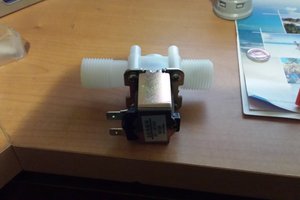
    The new design eliminates the reserve tank and replaces it with an electrically operated valve that connects to the outside faucet. It adds a five gallon tank of concentrated nutrient solution with a dosing pump. When the sump level switch indicates a low level it operates the valve and fills the sump to the "full" level. Logic is added to the NodeRed flow that measures Electric Conductivity (EC) to determine TDS each day, after the pumping session. This allows the solution to naturally mix before the reading. This is done three times a day so if enough concentrated solution is not added, it will be supplemented after the next pumping cycle. 

    I still need to create my temperature compensation lookup table. I plan on making a standard concentration of the nutrient solution, cooling it to the lowest temperature (50 degrees) and while heating the solution to 100 degrees, correlating the temperature with the EC. 

    I added my most recent code and schematic to the project files.

  • Nutrient Solution Maintenance and the Reservoir Revisited

    Todd Christell06/15/2017 at 19:43 0 comments

    I have been working on the instrument assembly that would be partially submerged in the nutrient solution sump tank; both from a reservoir refill perspective as well as a nutrient replenishment standpoint (compensating for evaporation and rain-fill). My plan was to handle these as two separate problems to be solved: deciding when the sump needs to refilled from the reservoir and measuring the total dissolved solids (TDS) in the solution and dosing with concentrated nutrient as needed.

    The reservoir solution was fairly straightforward. I was planning on a vertical tube that contained two magnetic reed switches: one each for low solution and proper fill level. A float would travel along this tube and as the solution level dropped it would eventually come close enough to the lower reed switch to close it, triggering a pump in the reservoir to start refilling the sump. The program would then monitor the upper reed switch and when the float reached the appropriate level, the switch would close and the pump would be turned off. I've been playing with this design and, using high density foam, clear rigid tube from the local aquarium shop, a neodymium magnet embedded in a high density foam float and two magnetic reed switches, the design seemed fairly robust.

    Next I started researching electric conductivity (EC) and total dissolved solids (TDS) measurements I found quite a bit of DIY solutions, including some great ones on Hackaday. I was worried about doing constant measurement because of electrolysis and the effect on the electrodes so was going down the road of doing one brief measurement each day. As it turns out, most commercial units use alternating current (AC) to help mitigate this problem although I did find one reference that was using the fast-read approach. I also discovered that temperature had a direct bearing on the measurement so, rather than being an interesting variable to measure, solution temperature is a requirement. So, with a little modification, my approach to measurement looked promising. When TDS dropped I was planning on injecting small amounts of concentrated nutrient solution with a peristaltic dosing pump. waiting until a scheduled bucket flood had finished (to mix the solution) then re-measuring and adjusting as necessary.

    Then the obvious became clear. The reservoir had several drawbacks. First, it was another tank that took up space, needed maintenance and most of all, had a finite volume. If I were gone for an extended period of time (vacation, during the hot summer when transpiration rates are highest) I would need a very big tank. Also, I could correct for a diluted solution from rain-fill with the dosing pump, but I couldn't correct for an overly concentrated solution. If I replaced the reservoir with plumbing to my outside faucet, and the pump with an electric valve, I could solve these problems.

    Starting out with a good basic design is important, but I really enjoy the dynamic nature of evolving the design.

  • Wi-Fi Range Test

    Todd Christell06/12/2017 at 00:02 0 comments

    Since the ESP is a remote node and accessed by Wi-Fi I decided that it would be wise to do some distance tests. Although the hydroponics setup is only about 50 feet (linear distance) from my main Wi-Fi access point it is located in the (totally submerged) basement so I wanted to check for any potential problems. I found one, but it wasn’t related to distance.

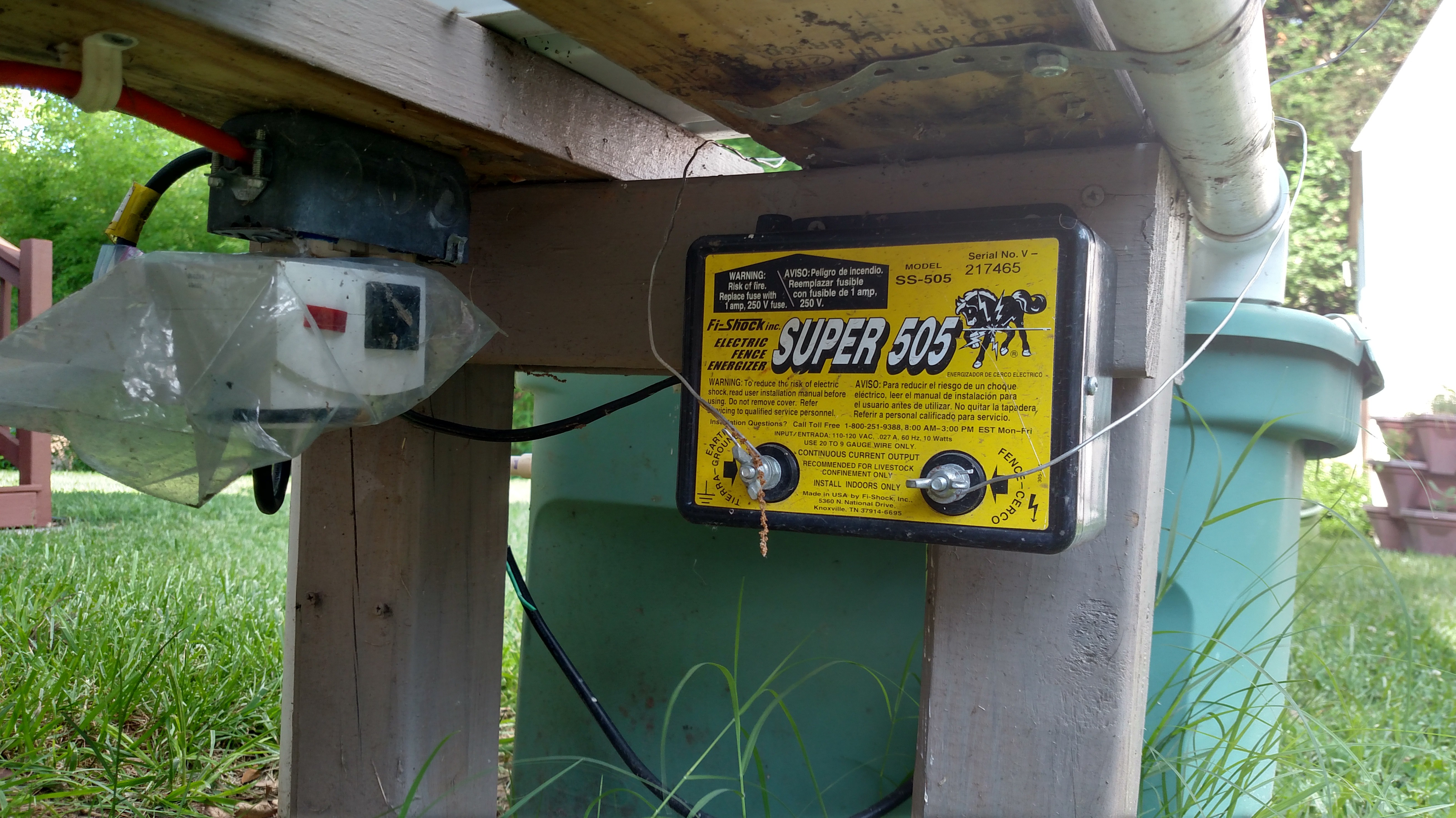
    I manually sent dozens of sump pump on/off commands but did not consistently receive acknowledgements. I moved the ESP closer to the basement window which did fix the problem. Since this appeared to be a range problem I added a “dash” to Node-Red which creates a web page that can be populated with buttons, gauges and graphs. I added a button to turn the pump on and off. This way I could be outside moving the ESP while triggering it from my phone. I discovered that I could actually get quite a bit farther from my access point than my hydroponics garden and get consistent results. It was only as I got closer to the hydroponics that things became erratic. Then something occurred to me. I have an electric fence charger to keep the squirrels from harvesting my tomato crop before I do. The charger doesn’t operate continuously but instead charges the fence periodically. When the fence was electrified it created interference with the ESP’s Wi-Fi. Sometimes it would get the command, but the acknowledgement was affected and other times it would not receive the on command at all.

    This is definitely a problem so I will have to figure out how to guarantee the receipt of the message. I could add a relay for the fence charger and have Node-Red turn the fence off before sending/receiving commands but I still have the same problem of guaranteeing that the relay command is received. Since the ESP sends a confirmation it would be relatively easy in a normal programming environment to go into a loop, resending the command until a confirmation is received. Node-Red has a “function” node but I’ve never used it so that may be an answer. The MQTT protocol also supports three Class Of Service (COS) modes but I seem to remember reading that the SubPub library on the ESP only supports a COS of 0. Another thing that I need to research. Although most implementations of this design won't have to deal with this type of interference it does cause me to consider how to make the communications more robust.

    The “real world” can really mess with a design…

  • Solution level, temperature and conductivity sensors

    Todd Christell06/11/2017 at 13:16 0 comments

    I started working on the sensor cluster that will be placed inside the sump pump container. I anticipate that this sensor group will do several things:

    1. Sense low solution level and send (publish) a request to Node-Red to turn on the reserve pump to begin refilling the sump.
    2. Sense high solution level indicating that the sump is full and send (publish) a request to Node-Red to turn the reserve pump off.
    3. Sense the temperature of the nutrient solution in the sump.
    4. Possible test the electric conductivity of the solution to indicate if the nutrient solution mix needs correction.

    This sensor needs to be relatively simple as there will be some mechanical aspects to it that could fail. It must also be water-proof as it will be submerged in the nutrient solution.

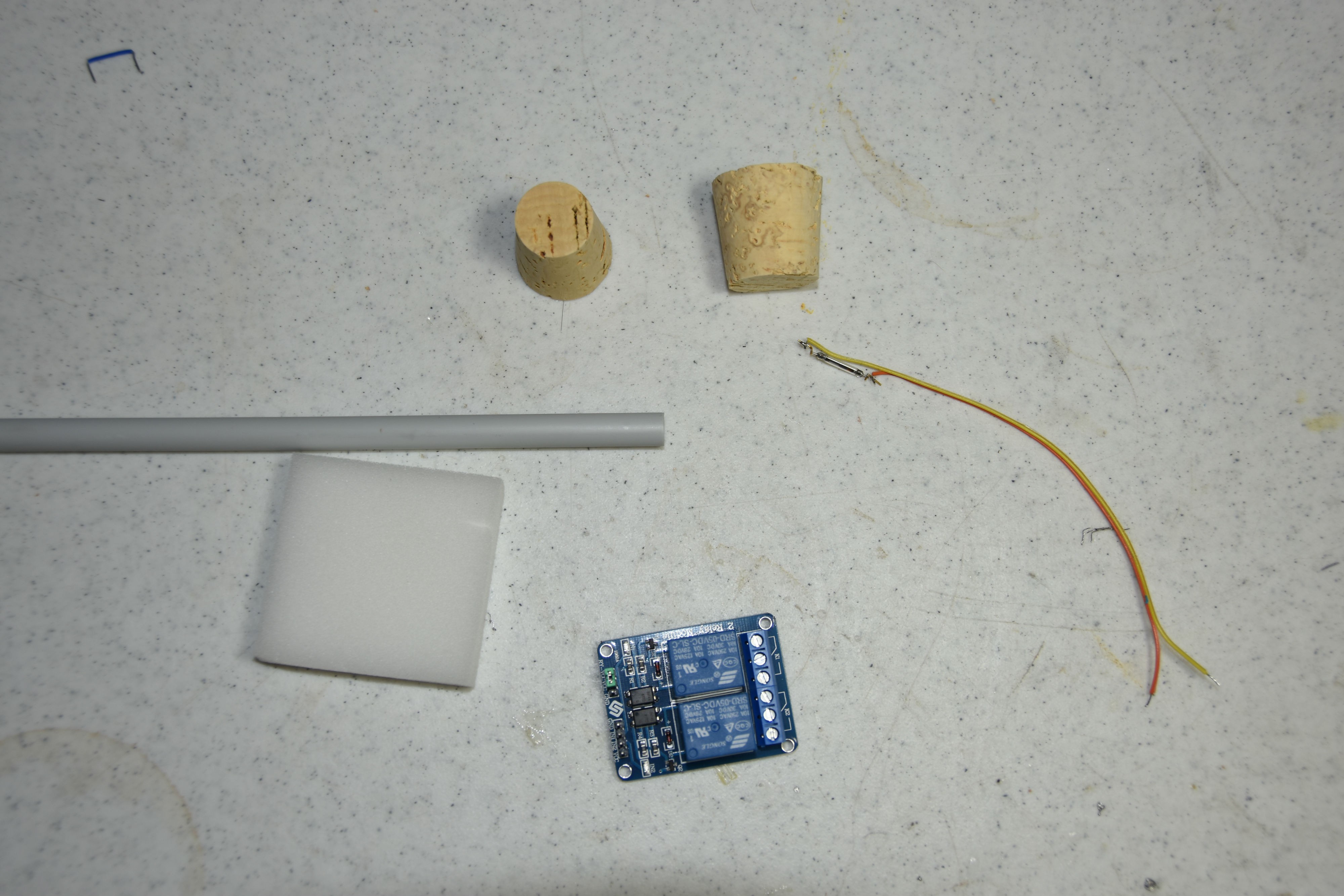
    My first design idea is to use a ridged plastic tube that holds two magnetic reed switches, each at the appropriate point to indicate low solution level and sump full. A float made out of something that floats could hold a neodymium magnet. This float would follow the solution level and the magnet would activate one of the two magnetic reed switches as required. I found two different corks as well as some high density foam to test as floats. I looked for rigid plastic tubing at the hardware store but the best that I found was grey water supply line. It isn’t really rigid enough and has a slight curve which could be a problem with smooth operation of the float. It would also be nice to get a clear tube to observe the location of the internal components. Ideally I can find a set of tubes that are rigid, clear, and easily nest. Then I could cut a small section of one to insert into the float to act as a sort of bearing surface.

    This tube could also house the DS18B20 temperature sensor providing the needed water-proofing.

    I’m trying to decide about the solution conductivity portion. It would be fairly easy to put two electrodes extending from the tube but I need to do some experimentation to see if this is valid. I have a small handheld testing unit that shows the level of dissolved solids but I have a feeling that it is more sophisticated than simply measuring conductivity. It’s possible that, although conductivity might not be a “laboratory” measurement, it might be enough to signal that the nutrient solution has changed.

    I've also included the relays that I plan to use to control the two pumps.

  • Dutch Bucket Hydroponics

    Todd Christell06/11/2017 at 03:23 0 comments

    Not really a post about my IUT project but it occurred to me that many would not be familiar with hydroponic gardening. Hydroponics is basically a way to grow plants without using dirt. The method I’m using is called the “Dutch Bucket” method. The plants are placed in a neutral growing medium, perlite in my case, and specifically formulated nutrient solutions are pumped from a large container (sump) into the plan’ts container which is allowed to filter down through the growing medium, both watering and feeding the plants. The solution goes to the bottom of the container where it is drained back to the sump. I run the pumps three times a day for 30 minutes each time. When the pumps aren’t running the perlite maintains enough moisture so that the roots don’t dry out, but also allow the roots to get air so the plant doesn’t drown.

    If you want to know more about Dutch Bucket hydroponics, mphgardner is where I discovered the method: https://www.youtube.com/watch?v=nXy32Dr4Z4A

  • Temperature Sensing and Initial Node-Red Config

    Todd Christell06/11/2017 at 02:26 0 comments

    The initial bugs are worked out of the Arduino code for the ESP8266. Pushing and holding the “sump low” button triggers the “sump pump” LED simulating the sump pump running. Then pushing the “sump high” button turns the LED off simulating the sump pump stopping.

    I decided to use DS18B20 temperature sensors for the nutrient solution and ambient temperature sensing. These sensors are reasonably accurate, small, inexpensive, and have good Arduino library support.

    I started work on the flow description in Node-Red running on the Raspberry Pi that will control everything. If you aren’t familiar with Node-Red, Richard Wenner did an outstanding step-by-step overview and installation YouTube tutorial at: https://www.youtube.com/watch?v=WxUTYzxIDns&t=379s

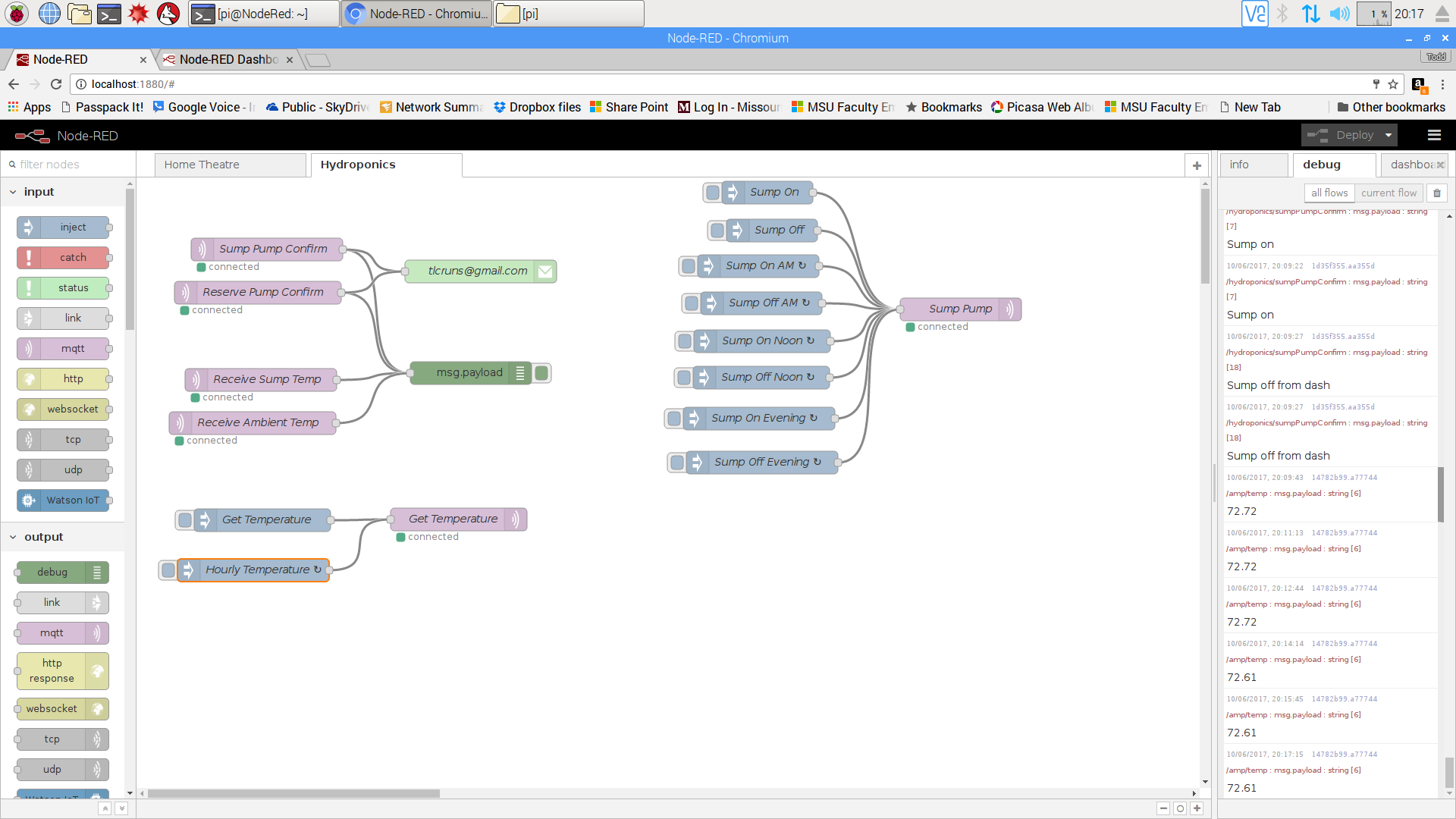
    My initial flows look like this:

    /hydroponics/sumpTemperature --> requests sump temperature

    /hydroponics/ambientTemperature --> requests ambient temperature

    /hydroponics/sumpPump --> Turn sump pump on(1)/off(0)

    /hydroponics/reservePump --> Turn reserve pump on(1)/off(0)

    /hydroponics/sumpPumpConfirm <-- Confirm receipt of sump command

    /hydroponics/reservePumpConfirm <-- Confirm receipt of reserve command

    I am using the Node-Red time inject function to turn the sump pump on at 07:00, 12:00 and 19:00 and run for 30 minutes each time. The ESP sends a confirmation which I display in the debug window as well as sending me an email for now. Since this is Wi-Fi and the ESP is going to be out in the garden I need some assurance, at least in the beginning, that it is receiving both pump on and off commands. For now the Pi is requesting both temperatures every hour (using Node-Red inject) and displaying them in the debug window. I intend on either logging these temperatures locally or possibly doing an integration with my Azure account.

  • Beginning Hardware Build

    Todd Christell06/10/2017 at 01:26 0 comments

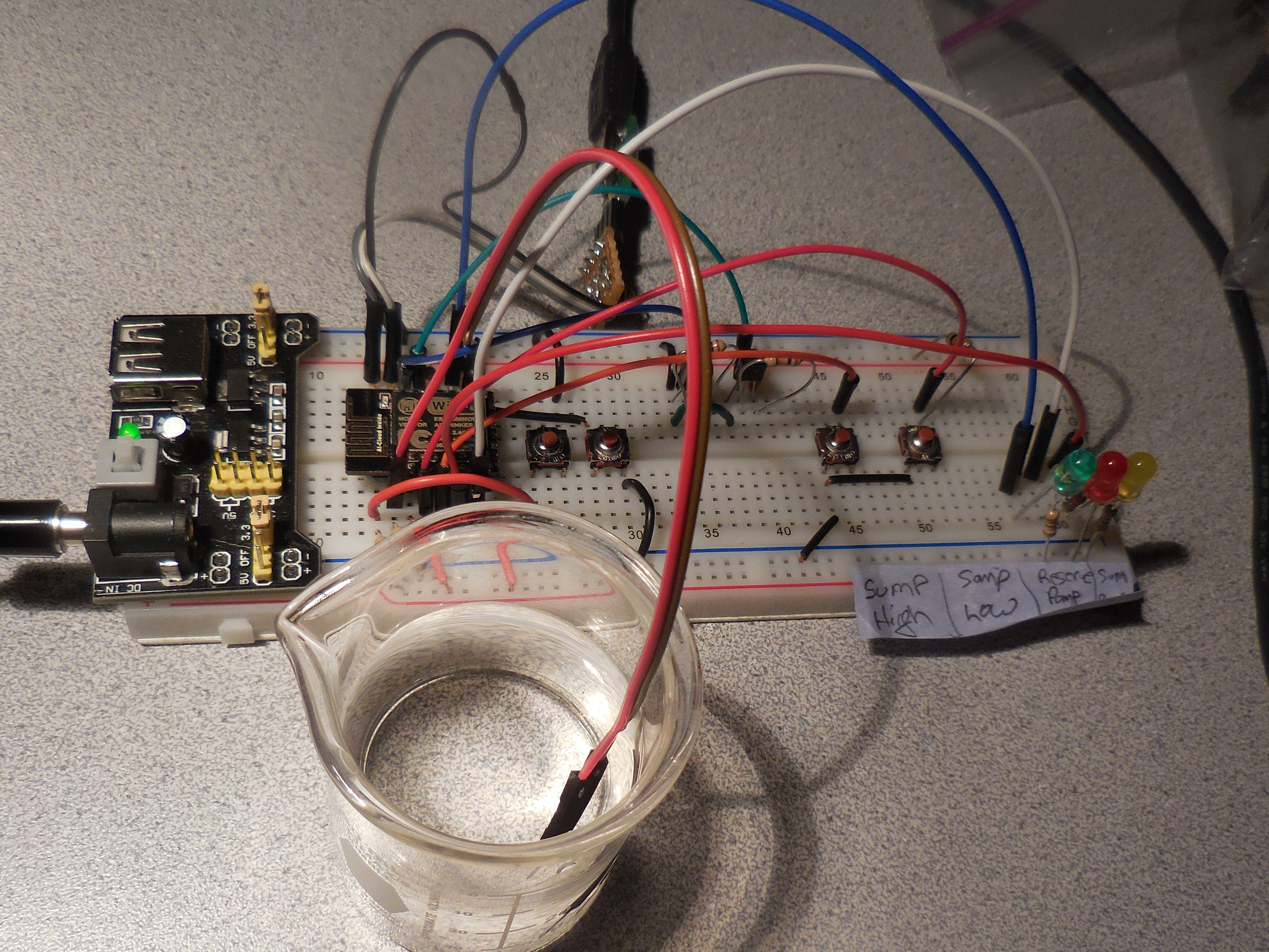
    I built an initial breadboard for this project. The two push buttons next to the ESP are for programming the chip since I want to easily debug my code as I add the hardware components. The next two buttons emulate the high and low nutrient solution mark for the sump. Pressing the "Sump Low" button starts the pump from the reservoir to refill the sump. This activity is represented by the red LED, indicating the pump is running. Pressing the "Sump High" button simulates the level indicator detecting that the sump is full and stops the reservoir pump and turns off the red LED. The sump pump is activated three times a day for 15 minute intervals to flood the growing tubs with nutrient solution. The command to turn this pump on comes from the Mosquitto MQTT message broker running on a Raspberry Pi and originated by a Node-Red service running on the same PI. Activation of this pump is indicated by the yellow LED.

View all 7 project logs

Enjoy this project?

Share

Discussions

Todd Christell wrote 08/06/2017 at 16:44 point

Geert2: Thanks for the links. Since TDS is really both the most important variable for plant growth but also the only one that I control in an outdoor installation so accurate calibration is important. I plan on researching this after the growing season (indoor projects for the winter) and have ordered one of the sensors. Thanks for the link. 

  Are you sure? yes | no

geert2 wrote 07/22/2017 at 04:30 point

The conductivity part is well researched by Mike at aquaponicslab.org (see 3 dollar sensor). you might be interested in finding this probe: http://banlinhkien.vn/goods-7625-dau-do-tds.html. It is standard in reverse osmosis machines, and cheap. It could be used at a scale and the standards facilitate calibration. The link is in Vietnamese, but aliexpress has also lots of sellers. 

I work on a similar project I hope to post later htis weekend. 

  Are you sure? yes | no

Similar Projects

Does this project spark your interest?

Become a member to follow this project and never miss any updates