 big_red_frog
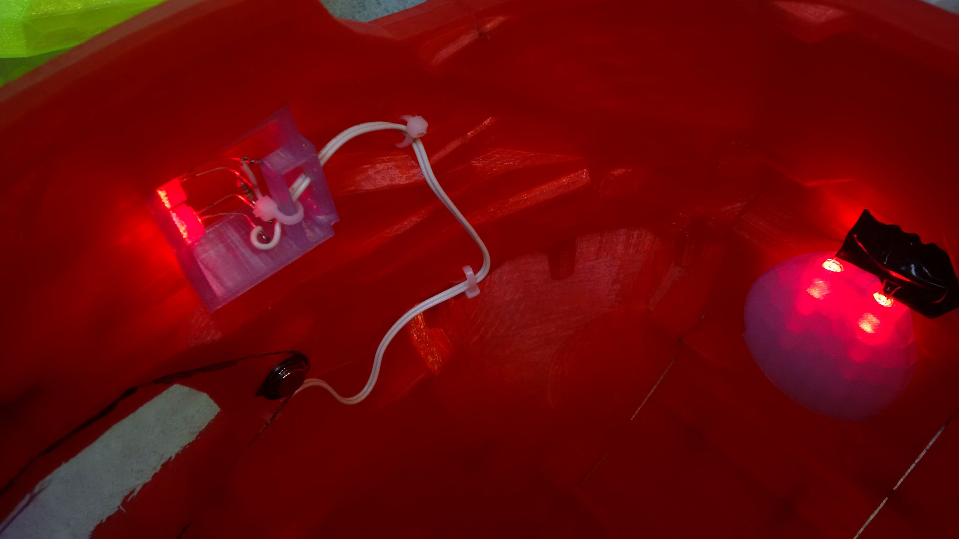
Print in place tie wrap mount points for wiring guides
http://www.thingiverse.com/thing:169295 and
http://www.thingiverse.com/thing:171912
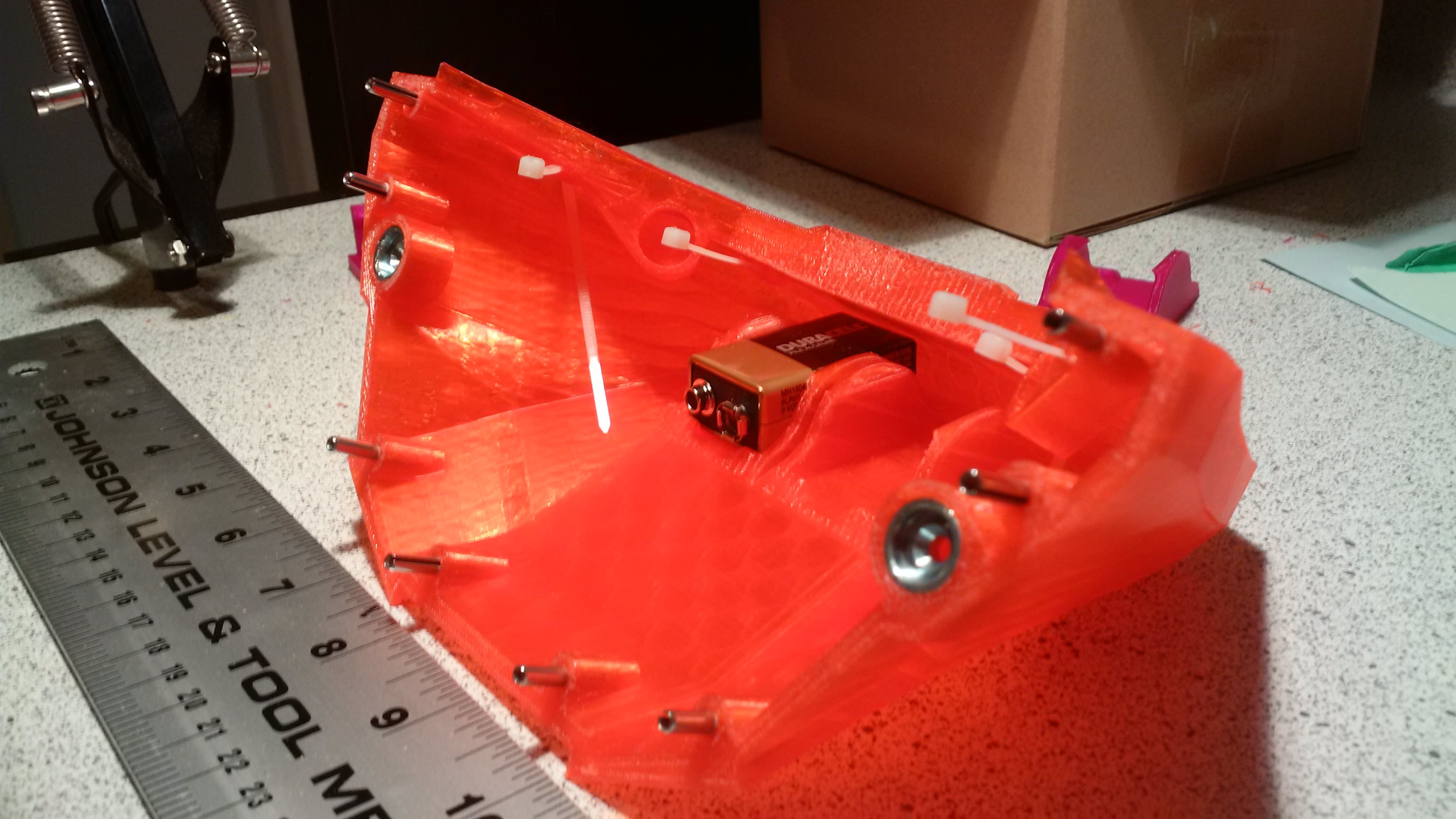
The present lighting circuit is very simple, soldering the resistor in series with each pair of 5mm LEDs. The resistor can sit directly between the LED's themselves, which makes soldering the twisted pins easy.
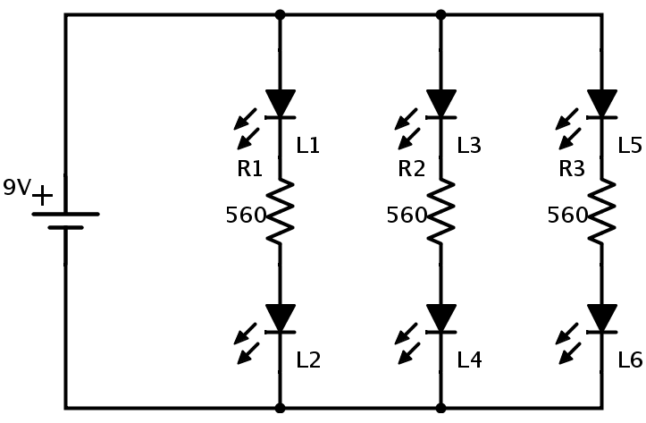
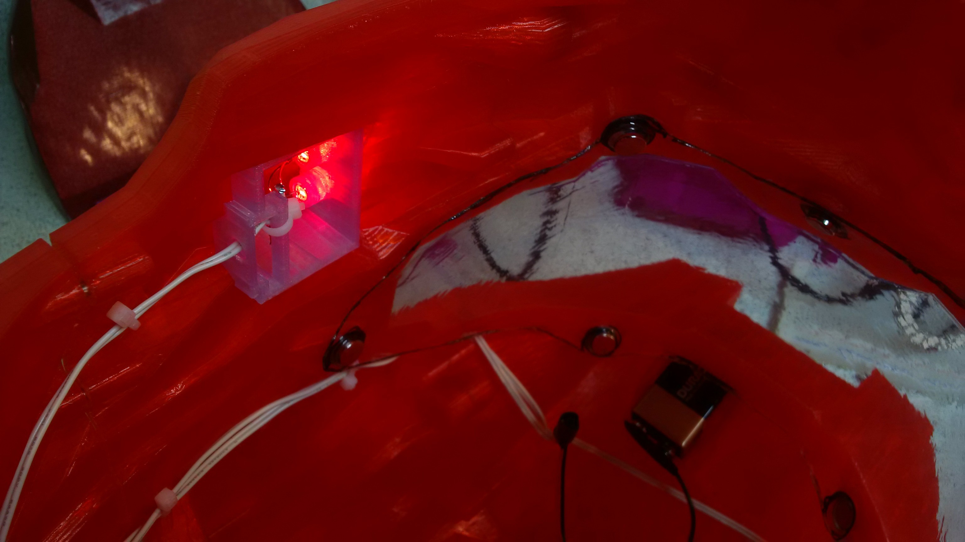
Here are the rear insert LEDs, with contacts taped off. Same combination of two 5mm LED's and a current limiting resistor.
Note all three pairs, 2 Jowls and the rear insert are wired in parallel to the 9 volt.
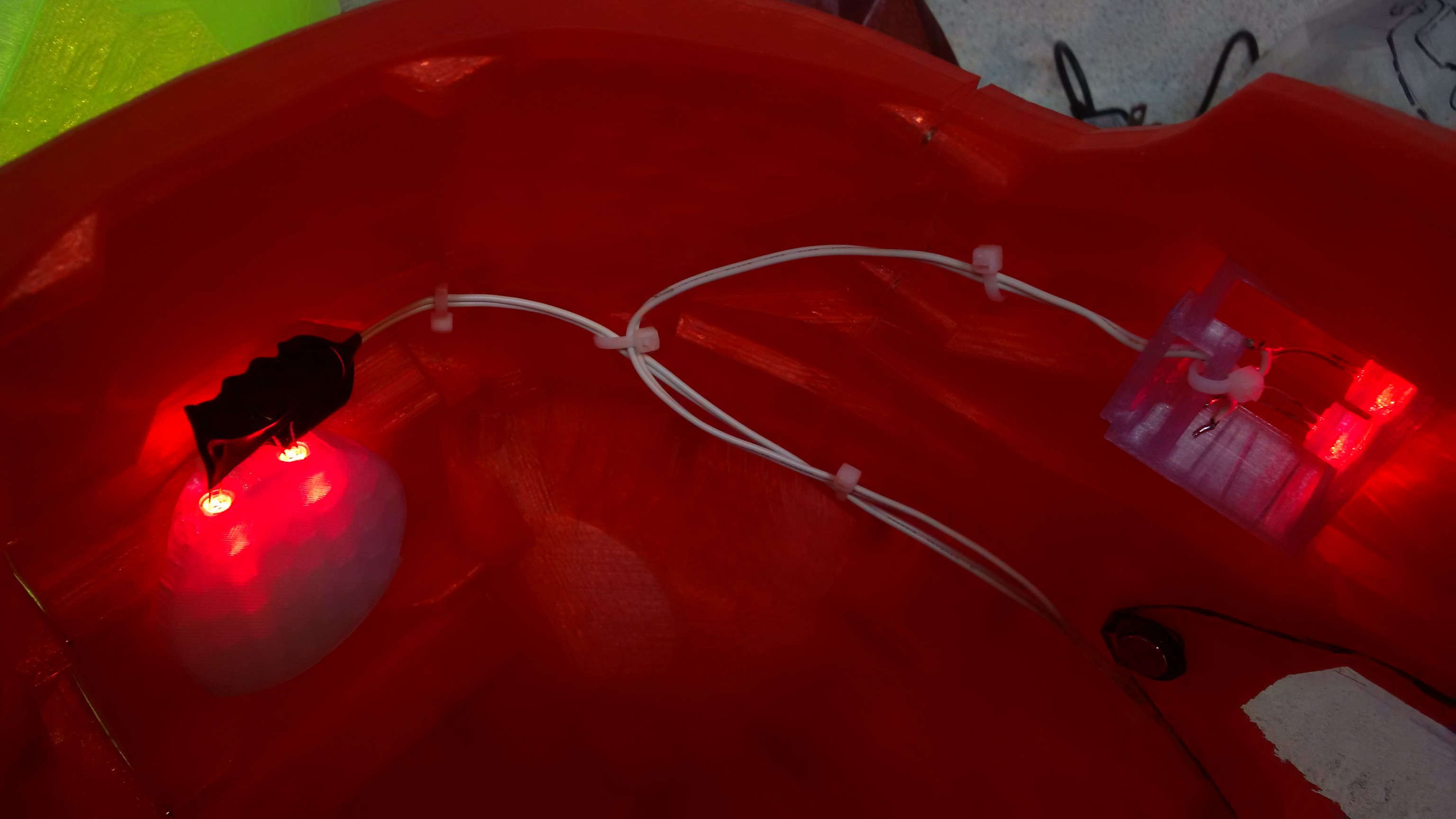 Here is the Jowl on the other side, which wires straight to the peak to join up with the other runs.
 I originally put an in line switch in the design, but it was more trouble than it was worth, and pulling the battery connector off is the preferred form of control at this time...
Discussions
Become a Hackaday.io Member
Create an account to leave a comment. Already have an account? Log In.