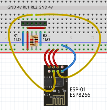
This project will use a circuit that I often use. It allows an ESP-01 to control a pair of relays.

Some issues to note
- The ESP-01 and the relay board are driven from a 4-volt supply. Even though the ESP-01 is rated for maximum 3.6v and the relay board is rated at 5v, I find that they both behave well at 4v. This means that I only need a single power supply.
- The ESP-01 has two GPIO pins available for use, but these must be pulled up with resistors to boot into run mode. This is why the two resistors are shown in the circuit.
- I actually only need one relay, but I have loads of these 2-relay boards. So it's not worth my while to buy a single-relay board. If you wish to use a single-relay board, you can remove the resistor R2 and connect GPIO-2 directly to 4v.
- The duplicated GND and 4v for the relay are for an odd reason. I have a selection of relay boards, and they randomly mix up the ground and power pins. So I have allowed for both combinations to be connected without crossing wires.
Discussions
Become a Hackaday.io Member
Create an account to leave a comment. Already have an account? Log In.