-
Cam generation program by user Shy Tavori
07/10/2017 at 05:38 • 0 commentsSince my last log entry, the project has gained mild internet fame. The best effect is that several people from around the world have added to the project. This log entry is about youtube user shy tavori's program that can be used to generate new cams from custom input paths.
Take a look at shy tavori's video explaining his program:
The program runs in 3D modeling program Rhinoceros. It uses an extension, Grasshopper, which adds block based scripting. I was not familiar with either application until shy tavori brought them to my attention. They seem like powerful applications.
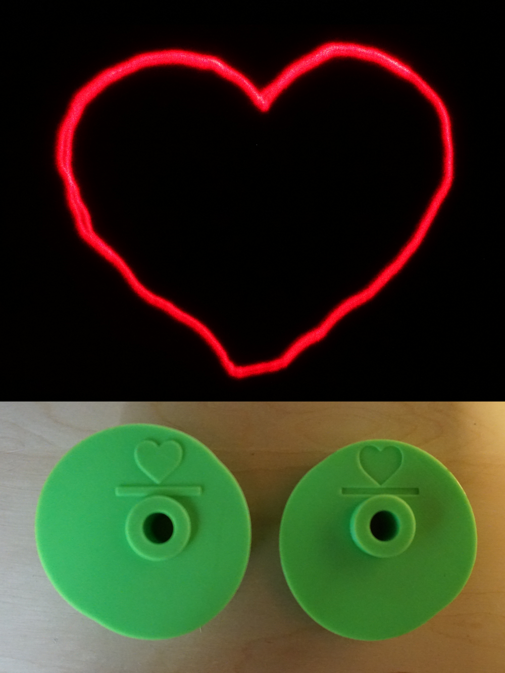
I used his application to create a new set of cams- the heart shape. I made this choice because several commenters requested it and it is very recognizable. This has been the simplest shape I have created so far which has several advantages:
- The machine requires less hand power to run
- Less intricate features give less opportunities for "valve float" which means less spring force required
- The outputted shape is larger
- as measured by the projecting angle in degrees
- Higher total image resolution
- The laser pen is moved farther. This is like printing a larger image with a constant DPI printer resulting in a higher total resolution.
- My printer has an XY accuracy of ~0.2mm. The heart cams have a radius range (max-min) of 9mm. This kind of gives an approximate resolution of 45 X 45 pixels. This sounds bad until compared with the batman shape has an effective resolution of 17 X 17 pixels. Note that these are back of the napkin approximations and more complex math is needed for exact tolerance calculations.
Custom cams can also be created with my Go application. I think shy tavori's way would be easier for the average person.
Here is the procedure I used to use shy tavori's work to create the new cams:
- Download/Install Rhinosourous
- Download/Install Grasshopper
- Download shy travori's grasshopper code https://www.dropbox.com/s/6n654qmxmp2vall/Custom Cams for MECHANICAL LAZER SHOW.gh?dl=0
- Open Rhinosourous
- Run command Grasshopper (opens grasshopper window)
- From grasshopper window, open shy tavori's .gh file
- Set correct laser radius (7.06)
- Rhinosourous -> change to front view
- Rhinosourous -> standard tools -> polyline
- Draw target shape in pink circle
- Grasshopper -> select far left item curve. Right click -> set one curve
- Select the target shape you created
- Grasshopper -> use slider to verify cams don't hit each other
- (you may have to disable the cam previews for this. To do so:
- select far right result -> right click -> preview)
- (you may have to disable the cam previews for this. To do so:
- Select far right result -> right click -> bake -> ok
- Select newly created cams
- Rhinosourous -> file -> export selected
- Do the same for the other cam. (other far right object)
I manually added the heart emboss/deboss for identification. The resulting models can be found on my Thingiverse page.
Check out the result:
![]()
Turned out great. Thanks shy tavori!
- The machine requires less hand power to run
-
Future improvements and features
06/13/2017 at 20:39 • 0 commentsAt this point I think it is unlikely I will continue the project. But if I did, here’s what I could do:
Blinds for discontinuous patterns.
Let's say I wanted to make a smiley face pattern. It would require the laser to turn on and off to keep the eyes separate from the mouth. The current system would not allow that because it can only trace continuous patterns. One way to allow that would be to add a blind wheel to one of the cams. This would spin with the cam and block the lasers light for part of the pattern.
Motor driven
Although against the original spirit of the project, I could achieve much cleaner patterns with more input power. This would also eliminate the need for the input crank and gear ration since the motor could drive the cam directly.
Web service for new cam creation
I already made the open source Go program that can generate cam profiles. That said, it is far from user friendly. I could foresee a user interface that allowed users to draw a pattern and click submit, and I return the 2 stl files to print.
-
Creating the video
06/13/2017 at 20:38 • 0 comments(See the video in the project details. Sorry about the ending.)
Filming the mechanical laser show presented 2 challenges- exposure and focus.
Exposure:
Photographing the POV effect is easy. Just set the exposure to over 1/5 second. Filming the POV effect is challenging. At 30 fps, each frame can have a conceptual maximum exposure of 1/30 second. Since your computer monitor is much dimmer than a laser, it does not create the full POV effect. Therefore in order to display the laser pattern like it is perceived in real life, I applied an After Effect called Echo. This effect merges the current frame into the N next frames, each time fading a predefined amount. This simulates what a human sees when a laser is moved quickly- a path that fades in about 1/5 second.
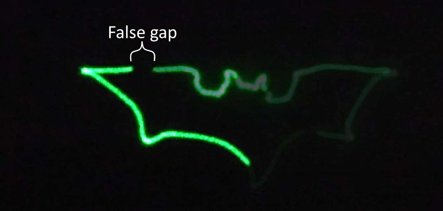
To further complicate things, my camera cannot actually take 1/30 second (= 33 ms) exposures while filming at 30fps. The camera needs time to read and clear the sensor before starting the next frame. In reality that takes around 3ms, leaving me with only 30ms exposures for each frame. That might not sound like much loss, but during that time part of the path was traced and it was not recorded by the camera. That results in false gaps in the video of the pattern. I did not attempt to fix this for the video.
![]()
Focus:
The laser show projects at a very small angle and therefore must be far from the projection surface in order to make a decent sized pattern. When filming both at the same time, the device must be much closer to the the camera than the pattern. With the required low light conditions is was near impossible to get both items in focus at the same time. See Hyperfocal distance . Therefore, in order to make both parts of the shot more closely match reality, I filmed it twice at 2 focus levels and combined the results in post. The Echo effect was only applied to the laser pattern part. Please see the below video for a raw, untouched version. Note that the laser point is out of focus which causes it to look much larger
-
Final design- Prototype 2
06/13/2017 at 20:30 • 0 commentsSince prototype 1 I made the following improvements:
- Actuating nose of pen instead of butt because the nose is lighter
- Hand crank on opposite side
- Cams facing forward
- Screws have less threads per inch for easier printing
- Cam design
Cams are now designed by software that makes far fewer assumptions. Software takens into account radius of laser pen and calculates a new angle for every radius.
-
Basic design finalized- Prototype 1
06/13/2017 at 20:29 • 0 commentsI decided on the final layout I ended up pursuing. Here was my first prototype that I actually modeled and printed. For the cam design, I made a single set of cams manually by hand once before I created the software. I made the assumption that the angle between every radius is the same (∠B from video = 0). This made it possible to create the cam, but resulted in a poor pattern.
Note that the laser faced "backwards" here.
-
Coming up with the basic design- Concept 2
06/13/2017 at 20:25 • 0 commentsConcept 1 from the previous project log had many limitations that caused me to discard it such as:
- Being driven by 1 cam gives it 1 degree of freedom. In this situation that prevents patterns that backtrace
- It requires the user to throw it around in the hand. That would result in large shakiness and error
- It would be very difficult to spin at the required 5 Hz
The last limitation led me to consider a similar design where gearing causes the cam to also spin in the opposite direction. After investigating a bit, it was clear this design was getting too complicated too quickly
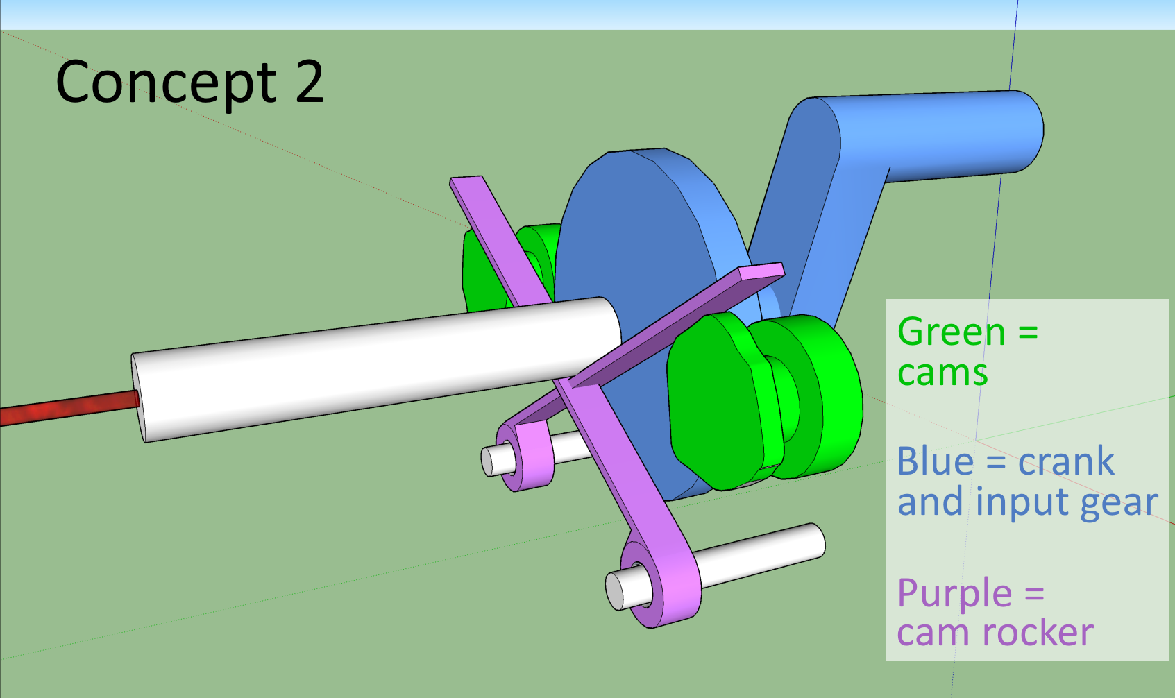
Concept 2
The fact that every part moved in the previous idea led me to consider a machine that had a stationary frame and was hand cranked. At this point it was clear that there needed to be 1 hand crank and 2 cams. I considered several variations including a design that had the crank gear in the center and the cams each connected to it. This used cam rockers to transfer motion from the cams to the butt of the laser. This and several other designs were eventually eliminated in order to reduce the part count for greater simplicity.
![]()
-
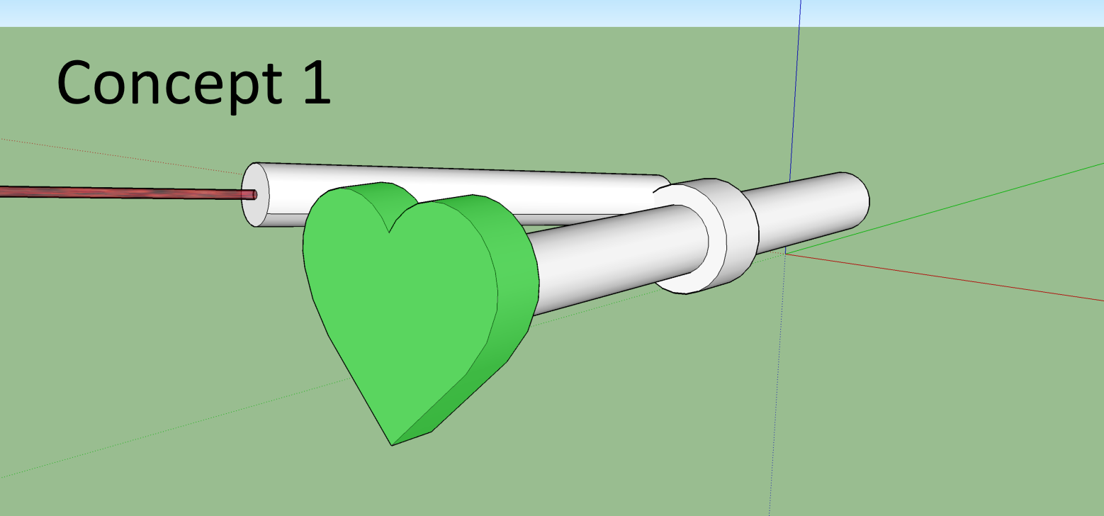
Coming up with the basic design- Concept 1
06/13/2017 at 20:23 • 0 commentsI am writing the project logs after the project has been completed by reviewing my notebook. These will still be in chronological order.
After coming up with the goals in the description, my first design was similar to a party spinner. Inputted power would come from swinging an off center mass around the axle. The user would hold the axle.
![]()
Mechanical Laser Show
device that projects a pattern by quickly moving a laser. all mechanical, 3d printed, hand powered
 Evan Stanford