-
The display -- she glows!
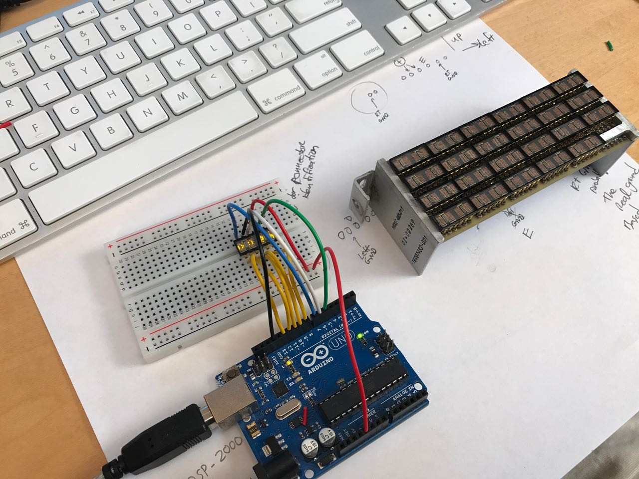
06/20/2017 at 10:33 • 4 commentsEarlier in the build, I demonstrated for myself that I could light up ONE of the little QDSP-2273 4 digit displays by connecting it to an arduino with some jumper wire.
Now my challenge was to make 24 of the display modules work at once. Theoretically, this should be simple. The display assembly I extracted from the box was already wired for all 24 to be daisy chained together. But I quickly realized that plugging the whole thing into an Arduino would be disastrous. Each column of the display has to be driven from my microcontroller, and the current requirement was easily 1 amp or more at 5 volts. This is quite of bit of power.
Normally, when I have power challenges like this, I turn to a MOSFET. For instance, this one from adafruit:
![]()
This device will let a microcontroller switch 30V at 60 amps, easily enough for this application. If I used 5 of these devices, I could switch each of the 5 columns of the display. Sadly, I did not have enough of these little guys laying around my workshop.
After some thought, I realized something important. The CDU/PMS unit itself probably had the same problem that I have. Its 1979-era logic gates probably couldn't drive that much current either. Somewhere inside the box ought to be some form of current switch.
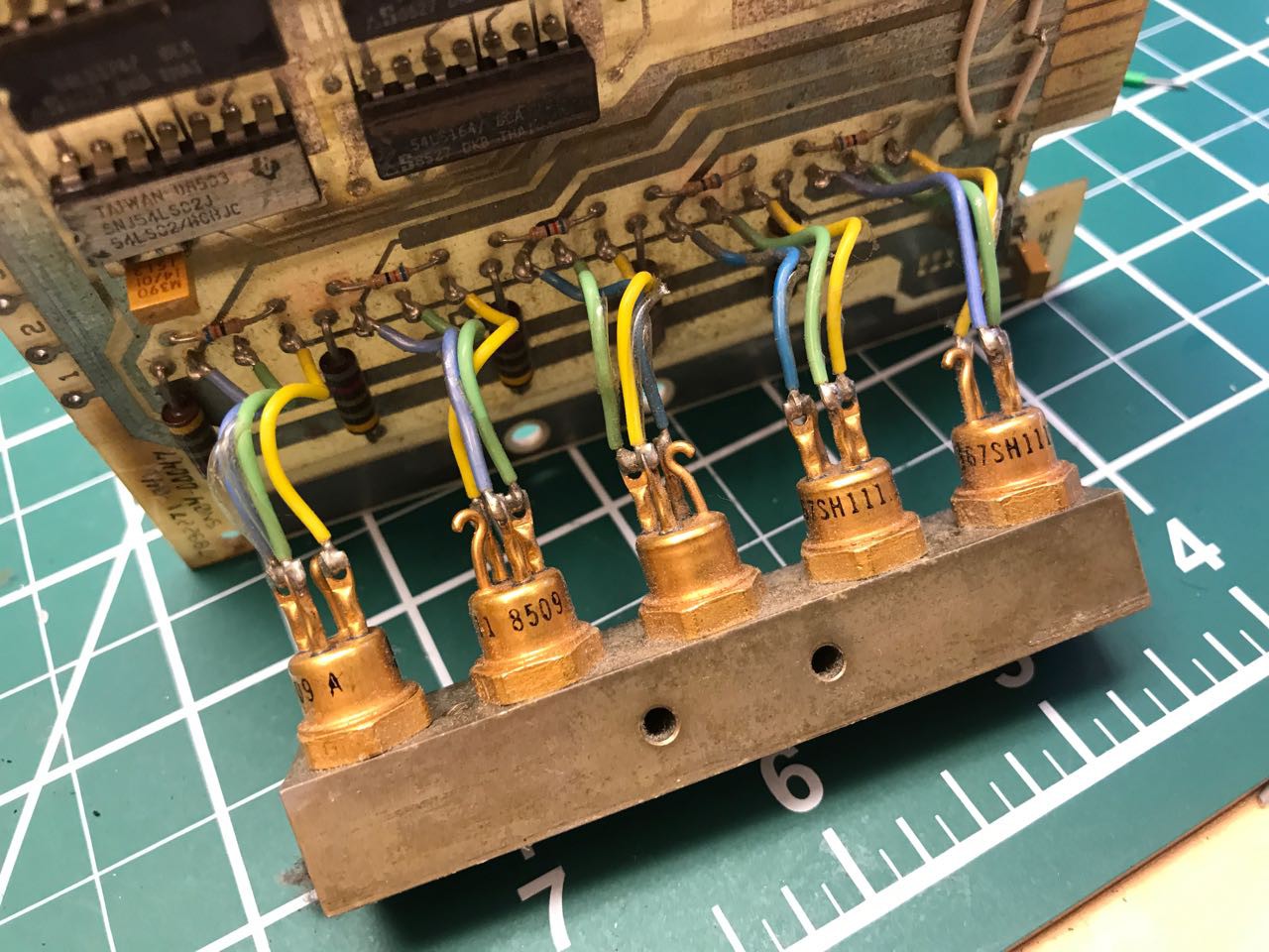
Sure enough, I found a bank of 5 transistors with a heat sink on one of the PCBs:
![]()
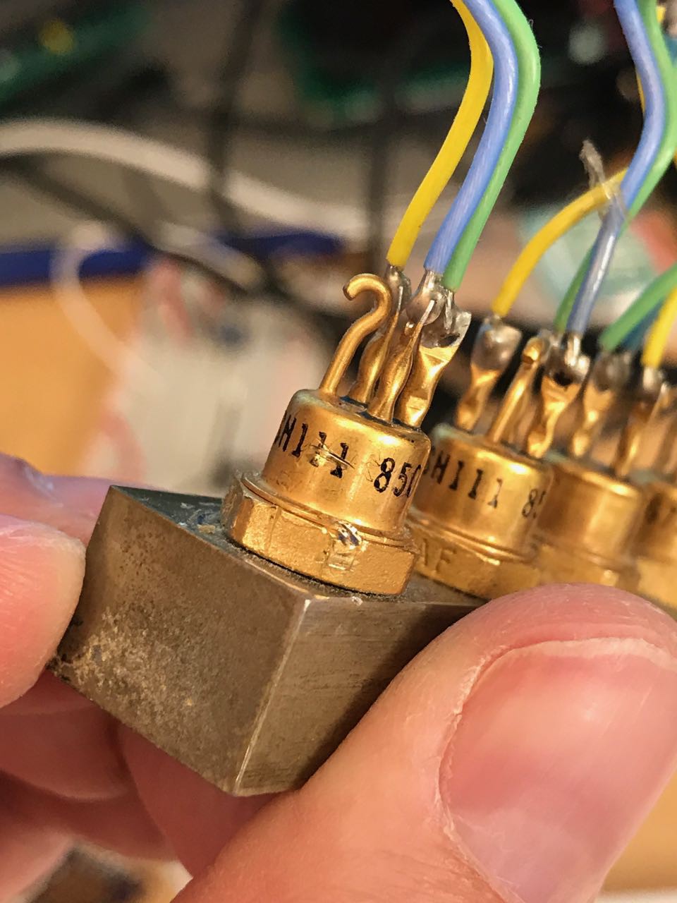
Look how cool they are! They even have their own solid metal heat sink and exposed leads.
Now a bit of cleanup and a part search..
![]()
I was unable to locate part number "S 67SH111 8509 A" so it would be important to prototype this first. Some quick probing with a diode meter, and I confirmed they were PNP transistors.
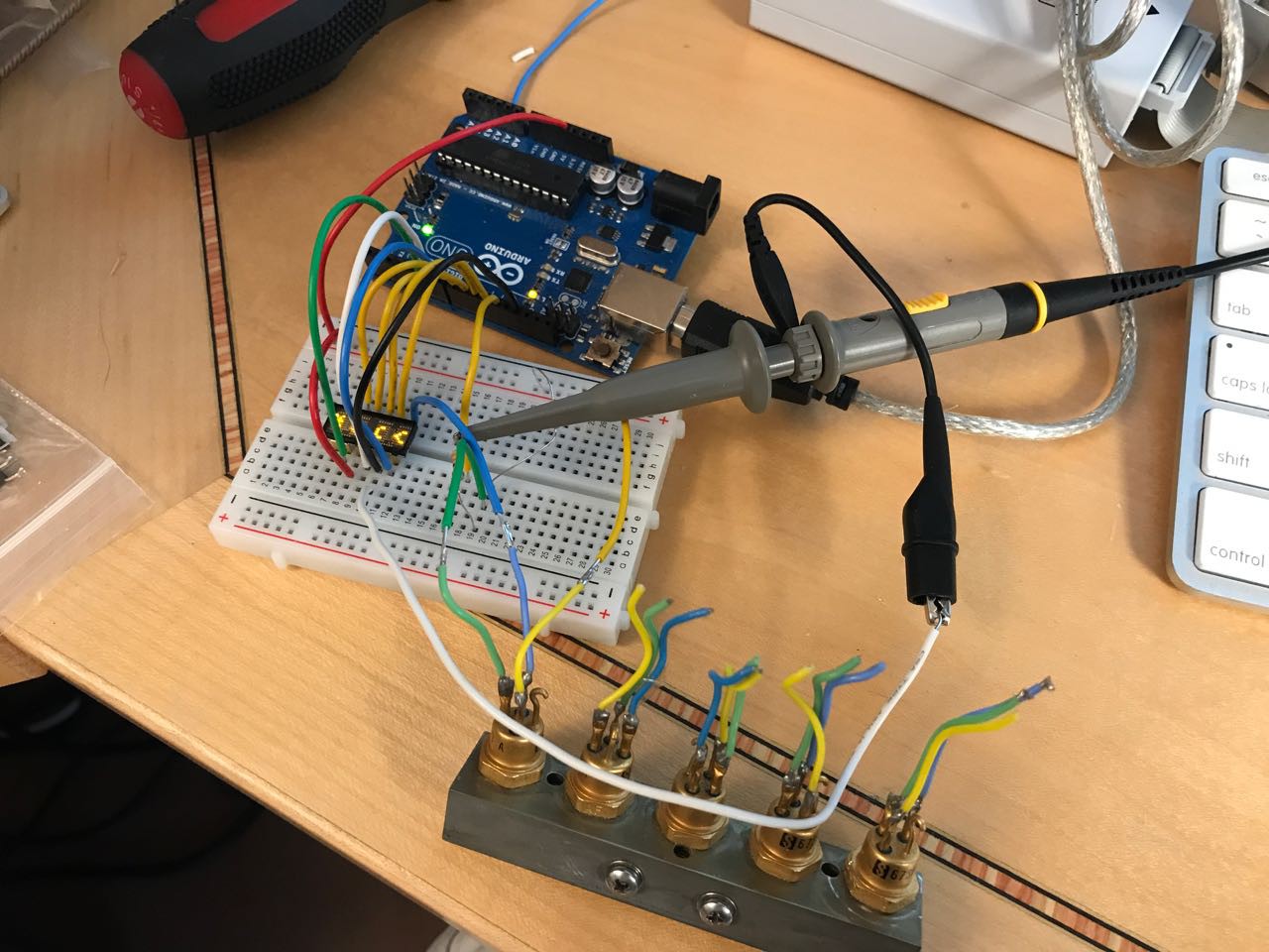
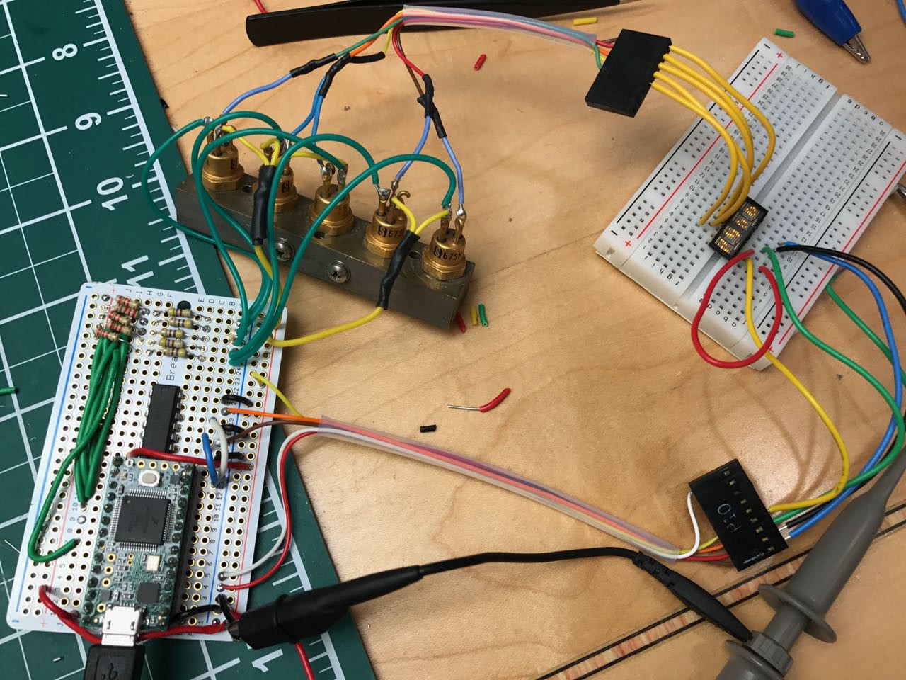
Below you can see my proof of concept. In this proof of concept, one of the columns is being driven through the transistor:
![]()
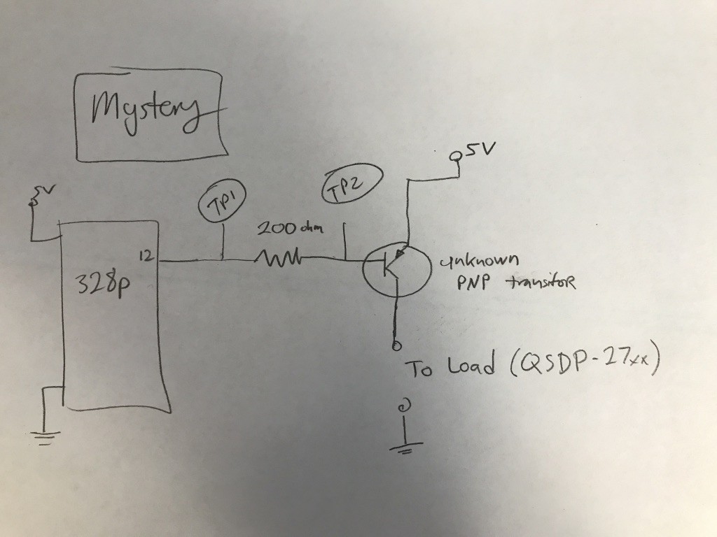
And here is the schematic:
![]()
Along the way I encountered a mystery beyond my current EE knowledge. Based on my primitive understanding of analog electronics, a transistor is basically a current-parallel switch. The current you feed into the base is magnified and becomes the current that passed through the transistor from the high-energy device. When you want the switch to be active, you lower the voltage flowing through a resistor and feed that into the "base" of the transistor.
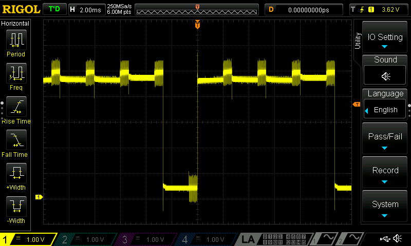
When I measured the voltage from the microcontroler, I see what I expect, which is a signal oscilating between 5 volts and 0 volts.
![]()
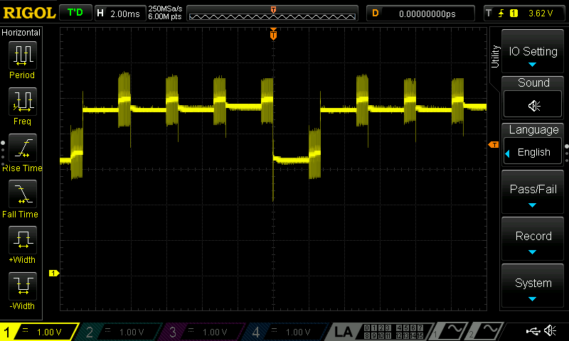
But when I measure from the base of the resistor, you can see the voltage doesn't actually drop to zero.
![]()
Is that just because the resistor is causing a voltage drop? If thats so, why does the transistor actually work at all? It barely seems to fall in voltage more than an volt!
Maybe in my next life I'll go back and take analog electronics in college.
In any case, the design seemed to work, so I decided to move on in the profound hope that what I don't know won't come back to hurt me. The next step was wiring up all 5 transistors and running a proof of concept test.
![]() For my full proof of concept, I decided to switch from using an Arduino to a Teensy 3.1. The Teensy is a 96Mhrz MCU board made by PJRC. It has far more RAM and speed than an Arduino and has been one of my goto components for my projects because of its excellent library and technical support.
For my full proof of concept, I decided to switch from using an Arduino to a Teensy 3.1. The Teensy is a 96Mhrz MCU board made by PJRC. It has far more RAM and speed than an Arduino and has been one of my goto components for my projects because of its excellent library and technical support. The only challenge was that while the Teensy is OK with receiving 5V, it doesn't actually drive anything higher than 3.3V from its pins. This is a problem - to turn my transistors off, I need to bring them to a full 5V.
After some vacillation around my design choices, I settled on use of a pull up resistor. To turn ON the display column switch, I drive the pin to its LOW state (0 volts.) To turn OFF the display column switch I switch the pin from an OUTPUT to an INPUT, which places the pin at a high impedance state and allows the pull-up resistor to bring the transistors's base to 5V.
Code to pull the pin low:
pinMode(column_pin[c], OUTPUT);
digitalWriteFast(column_pin[c], LOW);
delay(2);
pinMode(column_pin[c], INPUT);
I'm frankly not sure if this is a recommended practice (remember what I said about my level of EE training.) But it worked. Hopefully someone can help fill in my knowledge gap here.
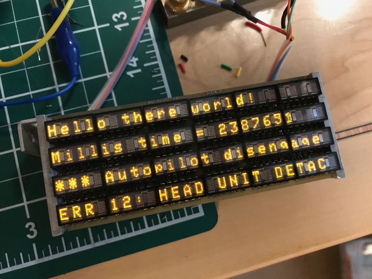
After some successful proof of concept tests, I decided to try writing text to the display. To do this, I needed to build a character generator that would take a string of ASCII and give me the dots to write out each character. In turn, I needed a 5x7 font to feed into the character generator.
As luck would have it, I discovered the work to create a 5x7 font had already been done by none other than LadyAda herself. After deciphering the font format, I managed to get the following proof of concept with some arbitrary text:
![]()
Success!!!
When all of these little display elements are on, the display generates a ton of heat. No wonder they are packed into a heat-sink!
-
Deciphering a 1970s era key panel
06/15/2017 at 15:31 • 1 commentAfter some initial success with the dot matrix display, I next took a closer look at the front panel. I was curious what it would take to decode what each of those wires did. Were each of them tied to a button? Or was there a row/column scanning type architecture?
Already a plan was forming in my mind. Now that I could drive the display, it suddenly seemed possible to restore the device to look and act like it did when it was installed on a 747-200. I could stick a 2017-era MCU inside and simulate the sort of interface that the device used to have.
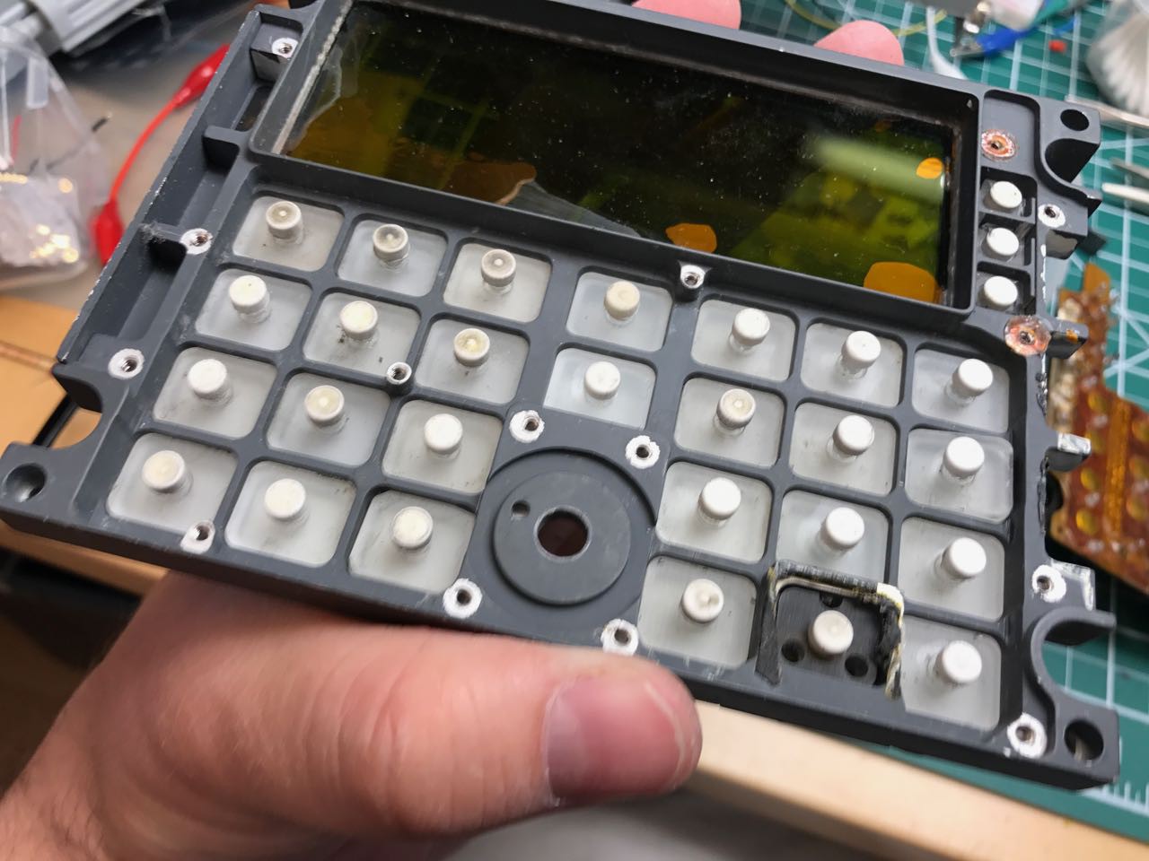
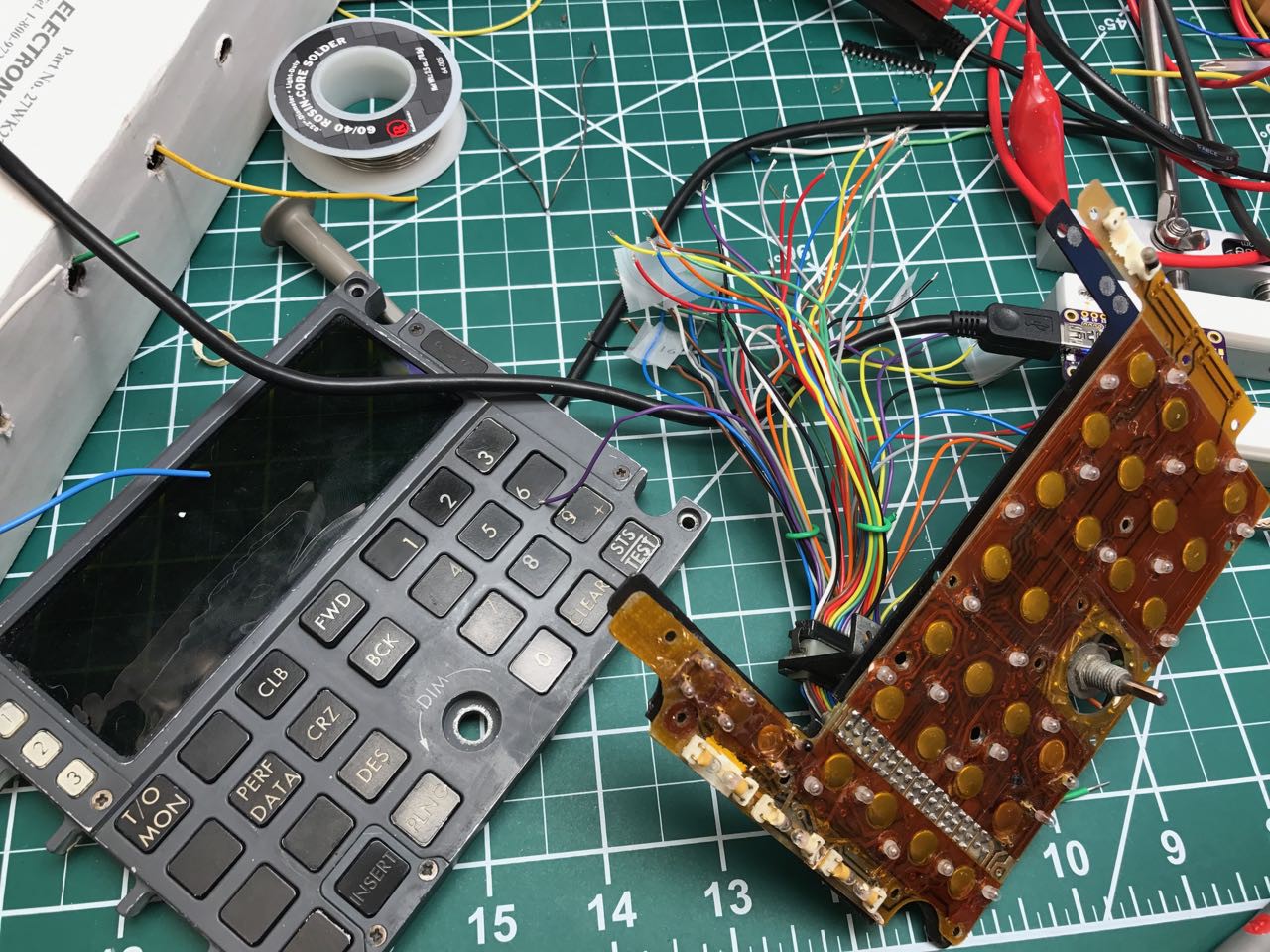
I started to disassemble the keyboard panel:
![]()
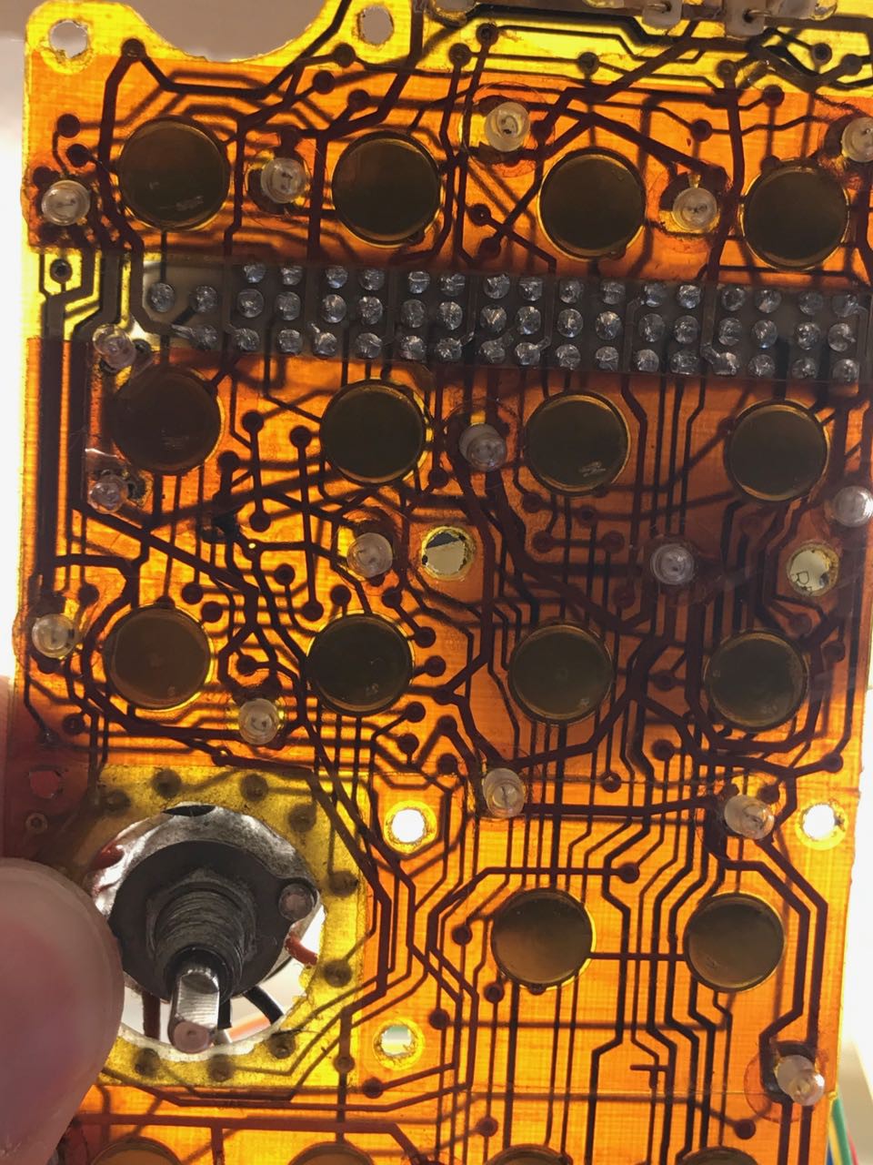
And rapidly saw that each key was not a microswitch but one of those dome contact switches that are mounted to the surface of the PCB. The wiring looks like the mask was hand-drawn - its basically a flex PCB with 3 layers.
![]()
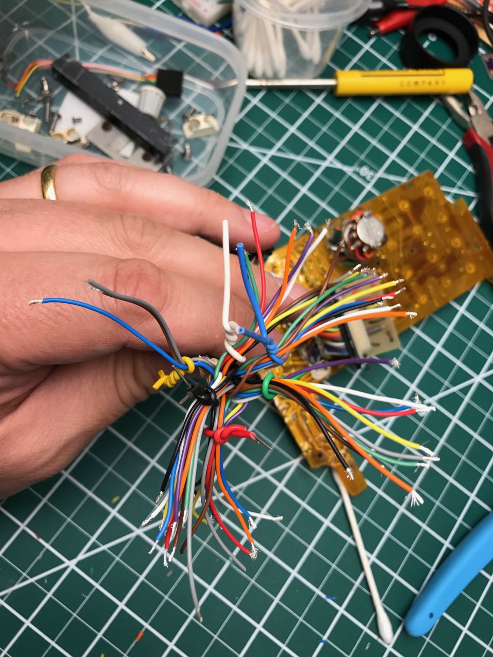
Was there any rhyme or reason to the layout or the pin assignments? I stared the painful process of finding out. First, I stripped down the wires.
![]()
Next I began a painful 3 hour journey with a continuity tester. The primary challenge was mapping between the trace on the PCB, the net back to the wiring harness. In most cases this was obscured and impossible to follow visually. However, after removing some of the kapton tape (they HAD kapton tape in 1979??) I managed to start figuring out where things connected on the PCB. Next was the mapping between the wiring harness and the actual wire. The actual connections were obscured by a gigantic blob of (probably toxic) sealant.
![]()
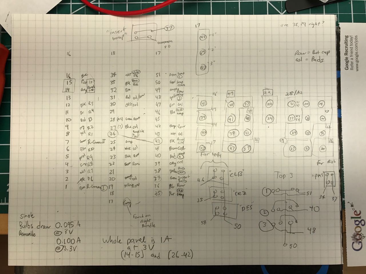
Each tracing step required mapping from the element on the PCB to the breakout, and then from the breakout to the wire.
Finally, i ended up with a pin chart like this one, now preserved for posterity:
![]()
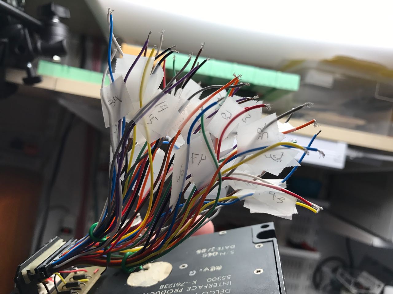
Along the way, I labeled each wire.
![]()
I can't guess how long that I spent on this but it was several evenings over the course of a week before it was done.
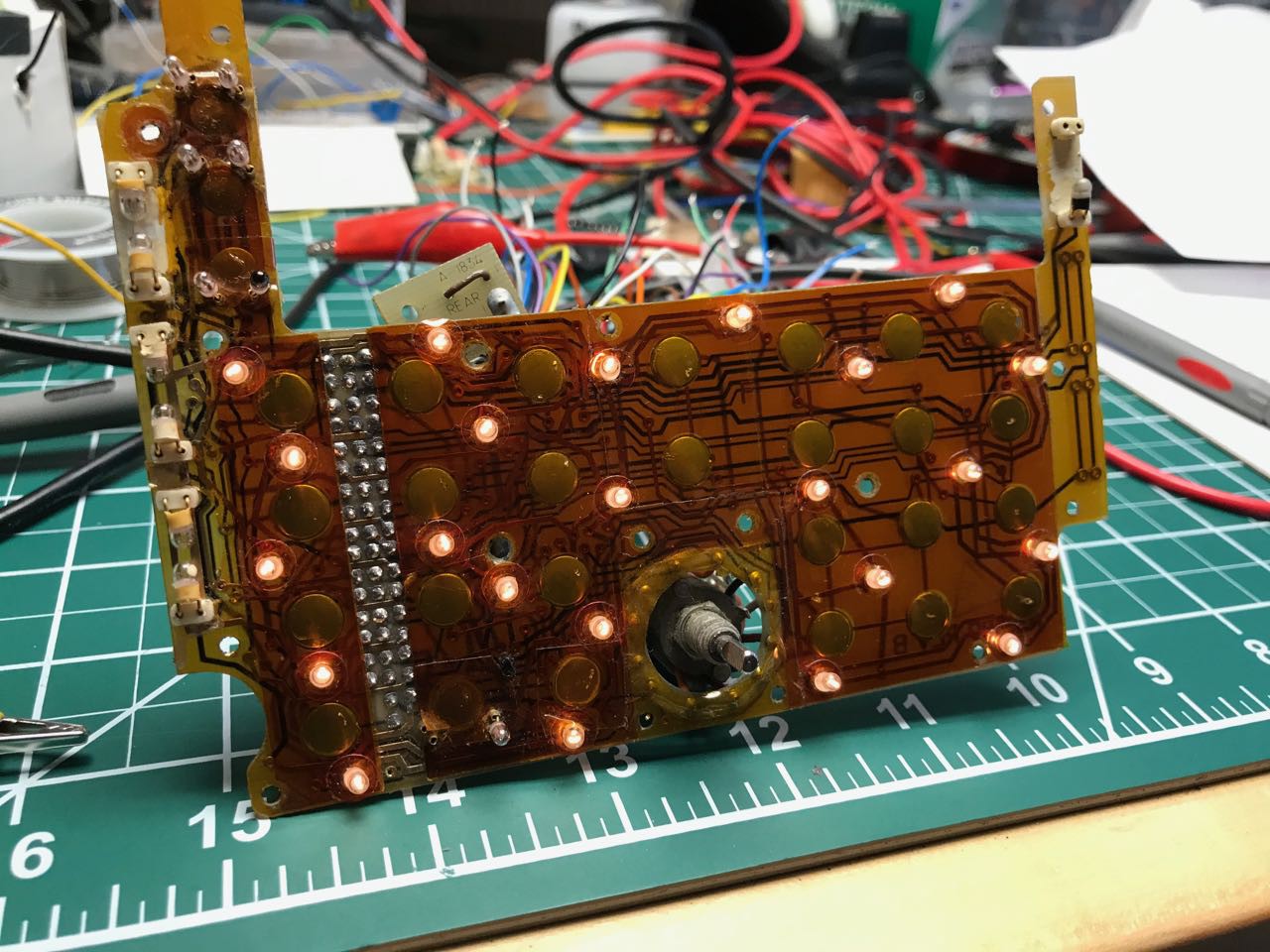
I also did some tests to make sure I understood the various lights on the board:
![]()
All of the lights you see on this board are basically grain-of-wheat ~3V incandescent bulbs. They are probably impossible to replace once they burn out now. Who makes 5mm incandescent bulbs anymore? [sadness] I'm hoping that if i drive these bulbs at under 3V i can get them to last a lot longer. The bulbs actually providing backlight illumination to the keyboard are surprisingly soldered directly to the PCB, and its unclear how you'd easily replace them given the copies amount of glue and kapton tape involved
-
The CDU arrives!
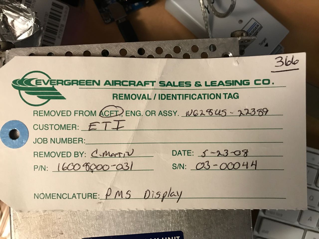
06/14/2017 at 16:57 • 0 commentsA week later, a giant box arrived at my doorstep from [aircraftstock]. I've ordered a few times from this seller and always been quite happy. He packs everything in dense bubble wrap. He also includes the inventory and removal tags on the device.
![]()
These tags are important because aviation equipment is FAA validated and I think in some cases you have to be able to demonstrate you know the provenance of used parts that you later install in a new airfraft.
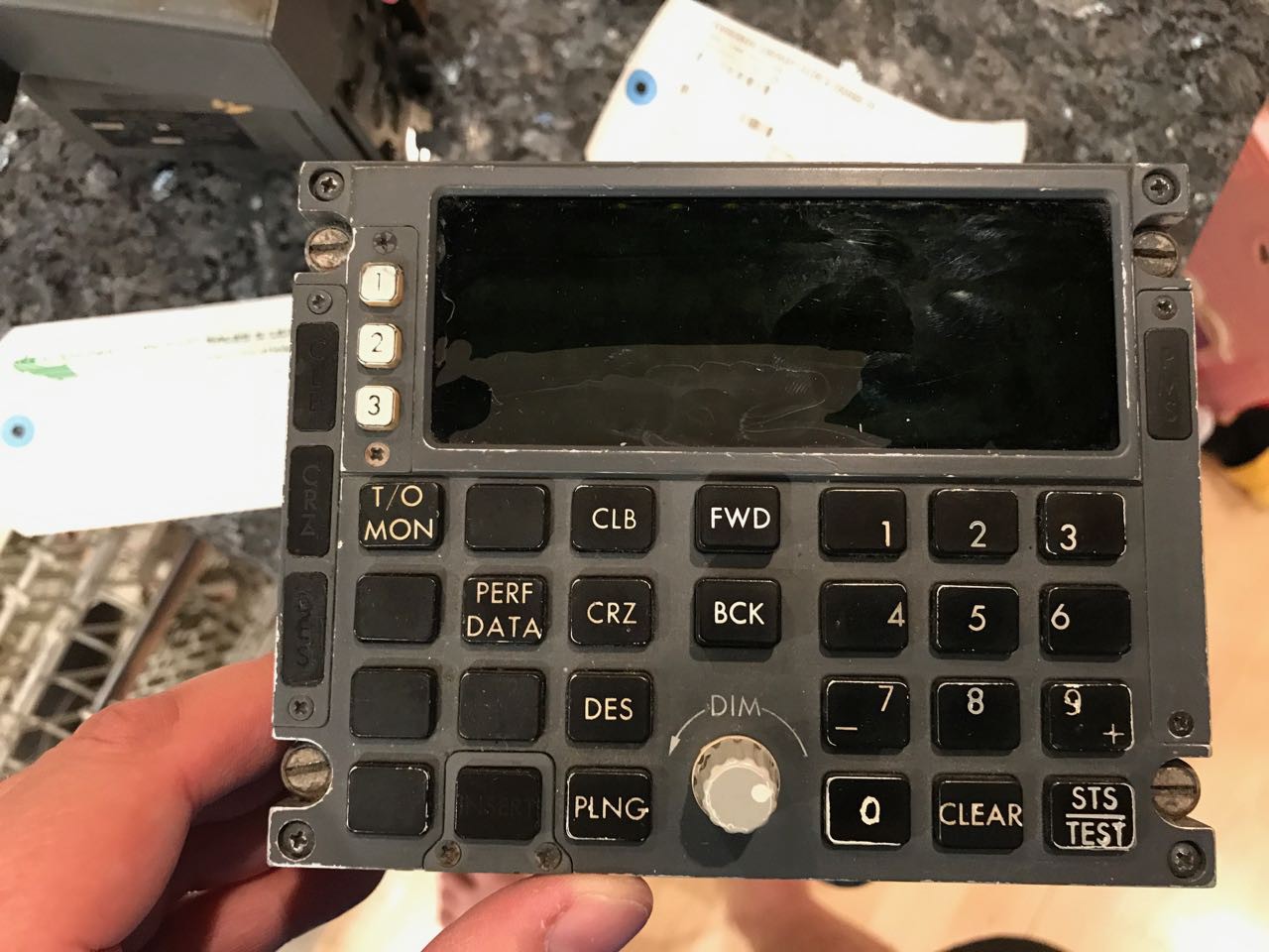
Wow, what a georgeous front:
![]()
Next I started with opening the case. A decade's worth of grime and aviation dust was apparent everywhere.
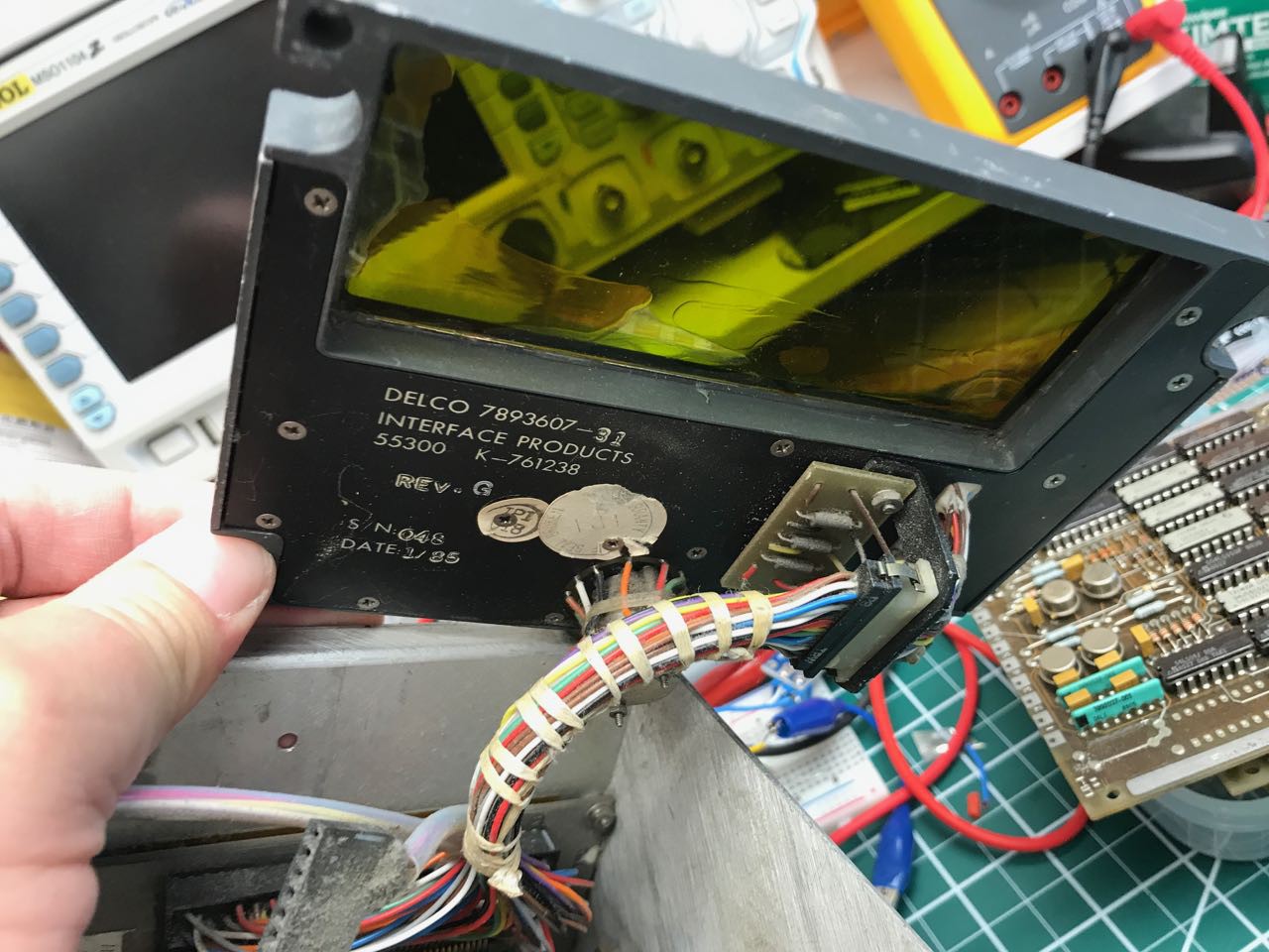
My first step was to remove the front panel
![]()
As you can see, it was tied to the rest of display with a 51 pin custom cable. Note how the wiring harness was hand-tied.
The display was especially mysterious. I had been expecting a VFD display. Instead there was this curious assembly made up of individual chips. I immediately thought of these retro dot matrix IC chips that I've seen on Digikey.
Behind the front panel and display are a row of removable circut boards. These boards contain all of the logic to drive the display and decode the keyboard and presumabley translate it into some private protocol that can run between the head-end unit and the avionics device.
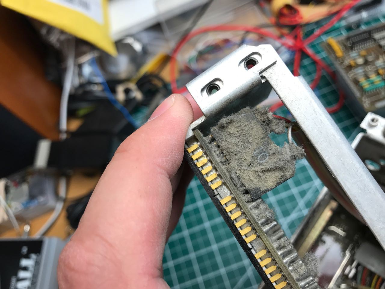
Here is a closeup of one of those boards. Have a look at the transistors and their massive heat-sink. This becomes important later.
The display subassembly was incredibly dirty. The first thing I noticed was that on close inspection it actually acts as a heat-sink. Look at how the chips sit up against a custom peice of machined metal.
![]()
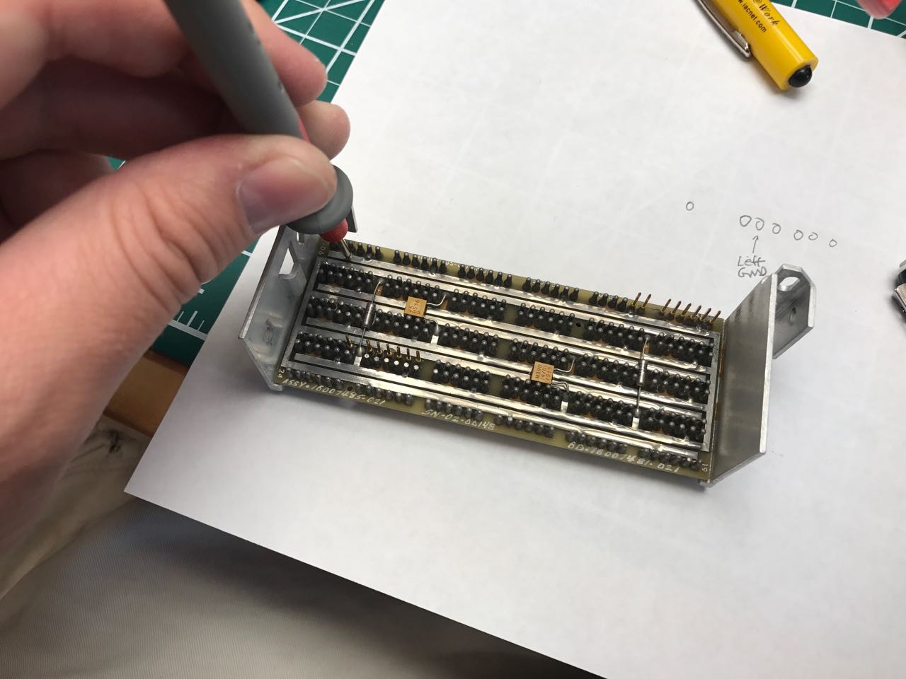
On the rear view, you can see how thick the traces were. I originally figured these must be power and ground, but actually I was wrong as you'll later see.
![]()
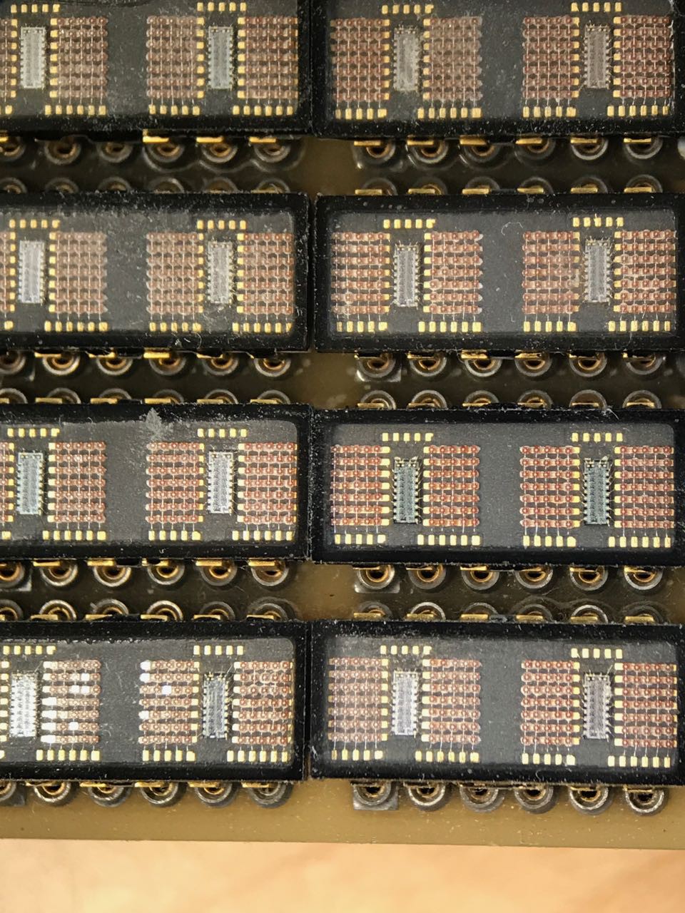
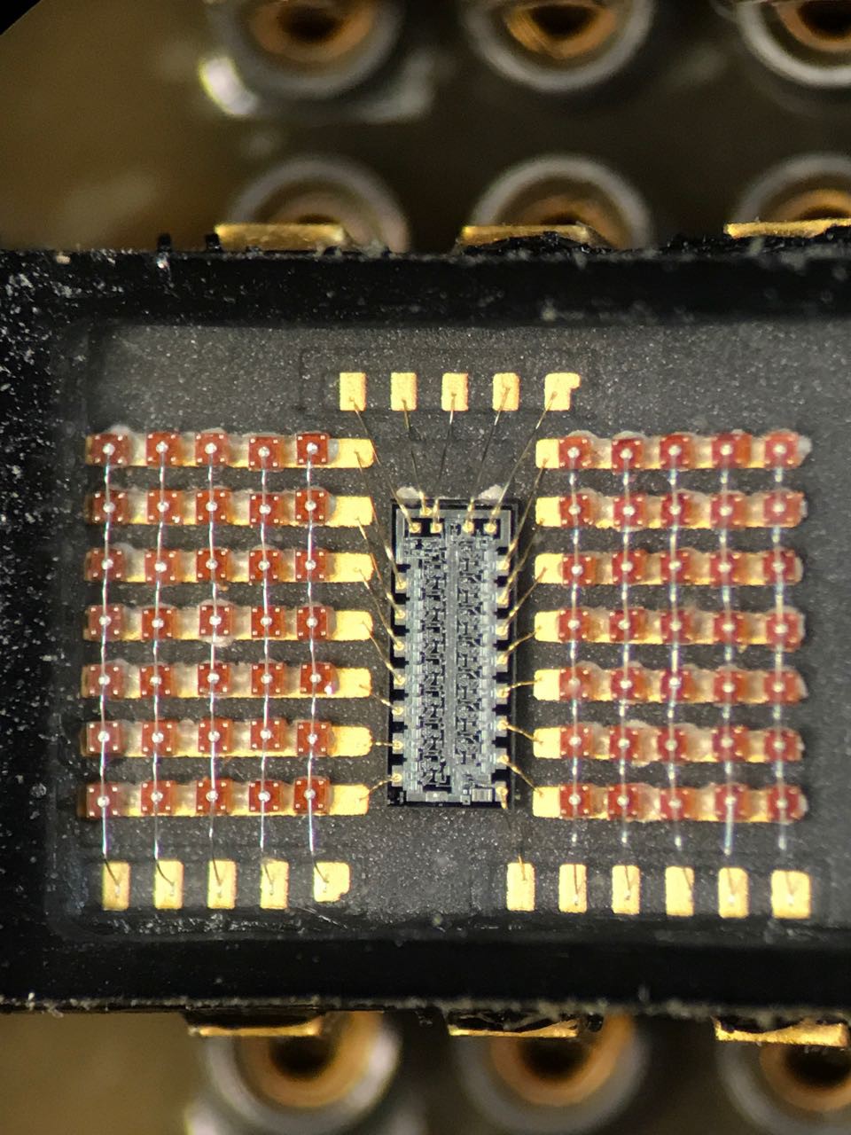
On close inspection each of the display chips contains two dies
![]()
Time to put it under a microscope and actually look at it.
I can't explain why, but the whole thing looks remarkably hand-wired. Maybe someone can explain why.
![]() I started mapping out the pins and traces. Again, I was assuming that the pattern was feeing power and ground to each chip and that was the reason for the wide traces.
I started mapping out the pins and traces. Again, I was assuming that the pattern was feeing power and ground to each chip and that was the reason for the wide traces. Next came a ton of sleuthing around. The chips were labeled as QDSP-2273. That part number doesn't appear anywhere on Google. But I did find this nice explanatory link for the type of technology used:
[Hewlett-Packard HDSP-2xxx Series - The Vintage Technology Association]
Hewlett-Packard first introduced the in 1976, as the display elements used in the HP 9825A desktop computer/calculator. Unlike HP's earlier multi-character displays which require external multiplexing circuitry, the HDSP-2000 is driven by four internal SIPO (Serial-In-Parallel-Out) shift registers, grouped in pairs in two planar dies housed within the display package. Serial data is shifted into the display in 28-bit words, and converted to parallel data which directs the multiplexing of the LED elements. All HDSP-2xxx series devices are packaged in glass and ceramic, and some models are actually built with red glass, a unique feature among the pantheon of early LED displays.
After some difficult pain with guessing search terms, I managed to locate an old PDF scan of the data sheet for the HDSP-2xxx series. The architecture is unusual. Its arranged where each ROW is a constant current sink driver that is connected to a shift register. Each column anode is actually driven externally. The idea is that you turn on one column and then serially clock out the row values. Then you turn on the next column and clock out the next chain of row values. Rinse and repeat.
Eventually I found that someone named [J Silva] had already managed to write an Arduino code example to drive one:
[Coffee, bits and bikes: HDSP-2000LP Arduino](http://bitsnbikes.blogspot.com/2010/05/hdsp-2000lp-arduino.html)
I spent another half hour carefully examining the traces of the PCB to see if this chip actually was wired the same way as HDSP-2000. I didn't want to make any assumptions. I was fully aware that I had only one shot to get this right, and it was unlikely there was a ton of ESD protection or polarity protection on the circuit. In other words, one wrong move and I've fried a chip I could never easily replace.
Eventually I convinced myself that the PCB actually was wired as though each were a HDSP-2xxx. It turns out the PCB is multi-layered and contains routing so that each chip gets their own access to 5 anode column drivers. Check one complete!
Next challenge was voltage. Airplanes use wacky voltage. In the past I've seen devices that expected everything +/- 48V AC to -5/+12 volts DC and everything in between. In the total lack of more information, I decided that this was probably TTL logic based on the era and that 5V was probably safe.
With the excited rush of a kid opening a christmas present, I giddily removed one of the chips and wired it up. I held my breath and applied power.
It worked perfectly! Thank you [J Silva].
![]()
Still giddy, I took photos and shared on twitter. I now knew I could potentially drive the entire display myself!
This demonstration, while exciting, raised some serious problems. For one, the current requirement was extreme. The single 4 character display was quite warm. I don't recall exactly, but I think i measured around 100mA just running the simple demonstration provided by [J Silva].
-
Getting started
06/14/2017 at 16:41 • 0 commentsFor many years now, I have been periodically scanning eBay of used airplane avionics, or aviation instrumentation. Once or twice a year I'll see something cheap enough (under $50) and fascinating enough that I'll buy. In the past I've restored or made operable all sorts of unusual little devices and learned a lot about the way complex instruments like this used to be designed.
The 747-200 CDU is my most ambitious project to date. This device is basically an early computer, probably one of the only computers actually onboard an airplane when it was designed. It was a predecessor of the now-common flight management system, which is basically a overall control system tying together the autopilot, auto-throttle, position, altitude and course management systems together.
This CDU is basically a "head end" terminal to a complex computer that lived in the avionics bay of a 747. This computer itself is long-gone, but for my purposes it doesn't matter.
I originally found this device on eBay. This is the listing:
![]()
The auction description reads:
This is a control display unit (CDU) used on Boeing 747 aircraft and possibly other types as well. This one has a parts tag showing removal from N628US on 5/23/08 during upgrade or tear down has been in storage since. It is in good condition without damage to the housing or connectors. The display is not cracked BUT has some delamination on bottom edge and all controls are in place. The data plate reads CONTROL DISPLAY UNIT, PART NO. 160080000-021, POWER 115V 400 HZ 0.8A, 5V 400 HZ 1.5A, CUST. NO. 60B40150, DELCO ELECTRONICS, FAA PMA 747 SERIES. It is not tagged and I have no way to test it so it is being listed AS IS. Thank you for looking and please see our many other aviation auctions.
This item was appealing to me because normally the PMS/CDU units are much more expensive. This one had a delaminated front which apparently knocked the price down quite a bit.
I looked up the aircraft N628US on PlaneSpotter:
![]()
Planespotters even has a photo of the original plane.
![]()
This plane was made on April 1980, and must have flown millions of passenger miles with its little PMS/CDU before it was decommissioned in the 2000s.
There is even a slight outside chance that as a young boy I even rode on this very aircraft! Back in the 70s I traveled from Boston to Portland, OR routinely with my family to visit my Dad's folks out west. I distinctly recall that often those trips would be on a wide-body plane like the 747. So who knows? It would be impossible to know now if I had ever ridden on N628US but I was certainly on a plane just like it.
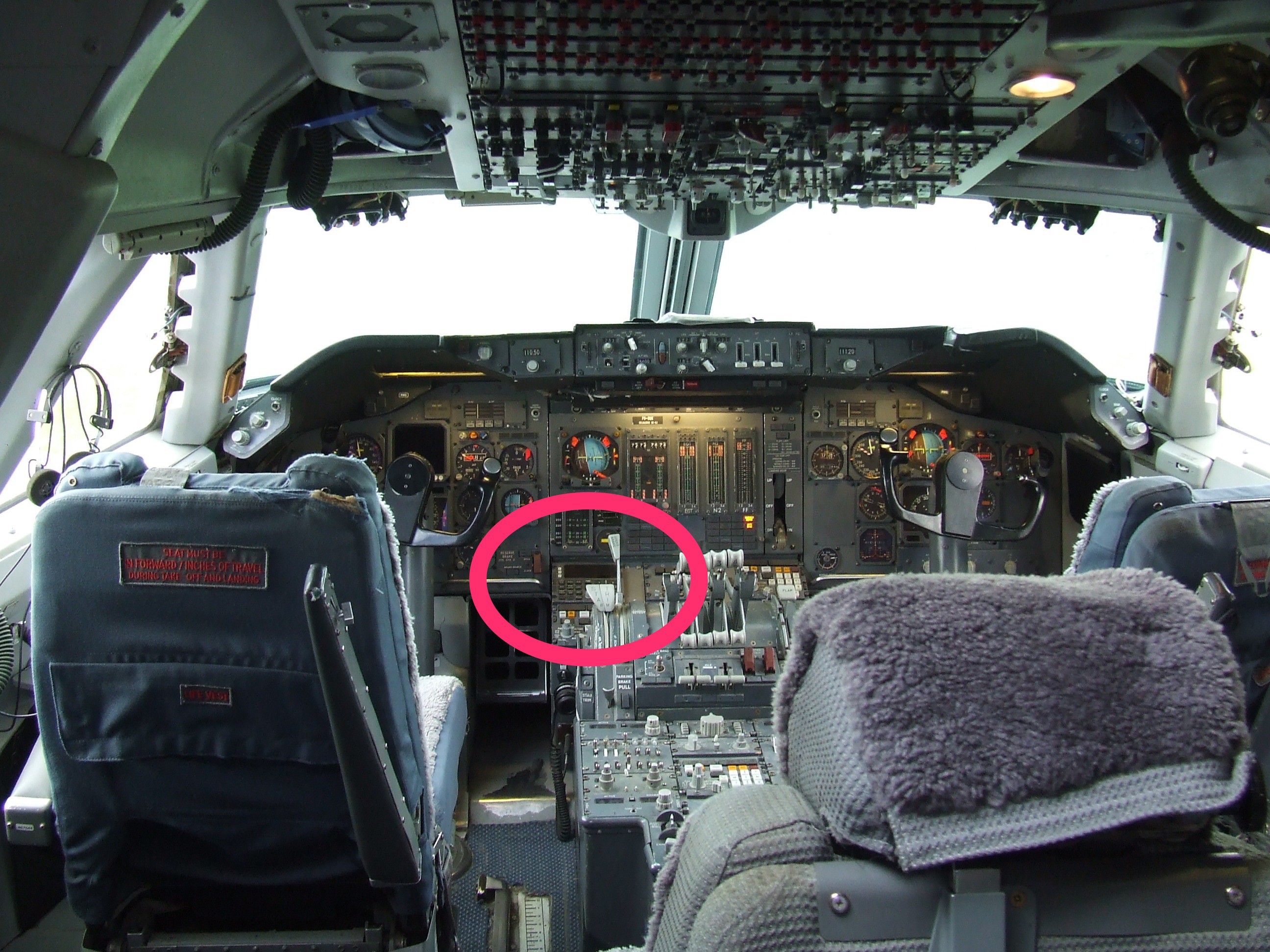
The PMS/CDU was only used on certain NorthWest Air 747s. You can see a photo of it here:
If you look carefully, you can see that this in fact is the ONLY interactive computer interface onboard the entire cockpit. The only other major "computers" on this aircraft that I am aware of were the INS and the Autopilot which have much simpler knob based interfaces and i'm not even certain if they were proper microprocessor based computers.
I posted a question out to Airliners.net and someone there was nice enough to read the description of what the PMS was supposed to do.
Performance Management System (PMS)
Introduction The PMS is an interface between the autopilot and the autothrottle. It calculates aircraft performance by using pilot inputs, stored data, and real time information from several aircraft systems. The purpose of the system is to provide fuel conservation and optimize aircraft performance.
The CADC and INS provide vertical climb rate and acceleration information to the PMS to determine if the aircraft is in climb, cruise, or descent. The PMS selects the applicable
control mode to become active when engaged. When engaged, the PMS provides outputs to the A/P, F/D and A/T to control the aircraft during climb, cruise, and descent.
The components of the PMS include:
control display unit (CDU)
performance management computer unit (PMCU)
switching unit (SU)
engine interface unit (EIU)
Boeing 747-200 PMS/CDU Restoration
Restoring a classic bit of aviation history with a modern twist
 Jeremy Gilbert
 For my full proof of concept, I decided to switch from using an Arduino to a Teensy 3.1. The Teensy is a 96Mhrz MCU board made by PJRC. It has far more RAM and speed than an Arduino and has been one of my goto components for my projects because of its excellent library and technical support.
 I started mapping out the pins and traces. Again, I was assuming that the pattern was feeing power and ground to each chip and that was the reason for the wide traces.