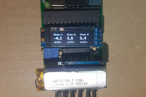
The IC itself needs a couple of registers to configure its range, and the red-coloured sensor module on the attached picture also contains a couple more resistors which form a voltage divider, so the module also offers voltage measurement capability.
The module is intended to measure power consumption of devices which use up from about a watt to about 60 watts. I don’t think it’s very precise in the low range. It outputs a voltage level on the Vt pin which is 5x lower then the input voltage, and outputs a voltage level on the At pin which is directly analogous to the current, i.e. for 1A it will output 1V.
By measuring the voltage and current output pins from the module, it’s trivial to calculate the power passing through the device. The device’s limits are about 3A for current and about 25V for the voltage (this one depends on the voltage of the MCU doing the reading of the analogue pin!).
Reading voltage accurately
AVR microcontrollers (and this is also true for most of the other families of microcontrollers) generally measure a voltage level using an ADC (analogue-to-digital) circuit which compares the desired voltage to the MCUs Vcc level, and outputs an integer in the range of 0 to 1023 (because the ADC has 10 bits of accuracy). So for an input voltage of 0 V, the ADC will output 0, and for an input voltage exactly equal to Vcc it will output 1023. To convert this reading into a (floating point) voltage, this equation needs to be used:
V = (reading / 1023) * Vcc
…or, in actual code:
float Vcc = 5.0;
float V = (analogRead(A0) / 1023.0) * Vcc;
Microcontrollers are often used in battery-powered devices, and this means the Vcc will change over time. If the Vcc value were hard-coded in the program (i.e. “5.0”), the voltage calculated in the above equation would soon become severely inaccurate.
Fortunately, the AVR MCUs have an built-in, stable internal voltage reference which can also be used to measure a voltage. The “stable” part means it doesn’t vary with Vcc and even to a large degree external factors such as temperature. Unfortunately, this reference voltage level is around 1.1 V, which means by default we could only measure voltages on the pin up to this level, and also, the reference voltage is uncalibrated, meaning its value, while stable for a particular IC, varies during the production process, so each chip has a slightly different internal reference voltage level.
Fortunately, again, the AVR’s ADC can be configured to measure the internal voltage reference, comparing it to the external Vcc, and if the Vcc is known, the internal voltage reference can be measured, and its voltage level calibrated. This allows us to attach a voltmeter to the Vcc pin and measure it precisely, then measure the internal voltage reference, and calculate its value from the same equation as above. With a bit of math, by measuring the internal voltage reference, the Vcc can be calculated and calibrated, which is done by the following code:
int readVcc() {
 // Read 1.1V reference against AVcc
 // set the reference to Vcc and the measurement to the internal 1.1V reference
 #if defined(__AVR_ATmega32U4__) || defined(__AVR_ATmega1280__) || defined(__AVR_ATmega2560__)
   ADMUX = _BV(REFS0) | _BV(MUX4) | _BV(MUX3) | _BV(MUX2) | _BV(MUX1);
 #elif defined (__AVR_ATtiny24__) || defined(__AVR_ATtiny44__) || defined(__AVR_ATtiny84__)
   ADMUX = _BV(MUX5) | _BV(MUX0);
 #elif defined (__AVR_ATtiny25__) || defined(__AVR_ATtiny45__) || defined(__AVR_ATtiny85__) || defined (__AVR_ATtiny167__) || defined(__AVR_ATtiny87__)
   ADMUX = _BV(MUX3) | _BV(MUX2);
 #else
   ADMUX = _BV(REFS0) | _BV(MUX3) | _BV(MUX2) | _BV(MUX1);
 #endif

 delay(2); // Wait for Vref to settle
 ADCSRA |= _BV(ADSC); // Start conversion
 while (bit_is_set(ADCSRA,ADSC)); // measuring

 uint8_t low  = ADCL; // must read ADCL first - it then locks ADCH
 uint8_t high = ADCH; // unlocks both

 long result = (high<<8) | low;

 result = 1125300L / result; // Calculate Vcc (in mV); 1125300...
Read more »
 ivoras
 mircemk
 Dr.Stone
 Thomas Van den Dries
 electronicsworkshops