Pierre-Loup M.
-
Boards received
07/19/2017 at 09:02 • 0 commentsHello!
The boards have been received a few days ago. They are really nice, beautifully looking, and... almost ok.
It has been a long way before I could start to debug and fine tune the program running on them. Three hours to figure out how to burn the bootloader and the main program, using an Arduino as ISP. Three hours to find out that some tutorials on Internet advice to set a 10µF cap between ground and reset on the board used as ISP, and that you need to set this cap. At least, on the board I used it was needed.
Then another three hours to understand why the display was not working. At all. No light, no blink, not even a wink! Three hours to read the program again, looking for anything that could go wrong, looking at the schematics of the board, looking at the gerber files I sent to the PCB supplyer. And finding absolutely nothing that could be the problem. And enventually, following the traces on the PCB, one by one, finding out that the decoupling capacitor and the iset resistor of the MAX7219 chip had been swapped by the manufacturer... 2 minutes, a tweezer and a small blowtorch later, the PCB was OK.
So, the program has been tested, debugged, re-written in some cases, and everything is fine! I'm really glad that, some program details and the components swapped by the PCBA manufacturer put aside, it came right by the first time! The timer does its job, and does it well! Time's missing this days, but the next step is of course to mount this timer into a UV printing bed to test it in real conditions!![]() The finished timer. It just lacks the encoder button.
The finished timer. It just lacks the encoder button.![]() The C2 capacitor and the R2 resistor. Very close components, with the same index, I understand they swapped them. But i would have preferred they didn't! :)
The C2 capacitor and the R2 resistor. Very close components, with the same index, I understand they swapped them. But i would have preferred they didn't! :)
Some considerations about the design, with boards in hand. Even if I tok some time to think about the depth of the trough holes components, it appears that the relay is much more high than the display, button and encoder. I had to mount it on the bottom, to have everything comming at the right level once it will mounted in a printbox.
Using a Atmega8 was maybe not an idea that good: I program the fuses so there's no bootloader, but the program uses almost all the memory on the board, so there's no more room for someone to expand it to suit his needs. I'm not sure the price difference between the Atmega8 and the Atmega328 is worth it. The footprint being the same, maybe I'll change it... -
Boards ready to go!
07/05/2017 at 19:33 • 0 commentsI've received this morning a short e-mail from the PCB manufacturer. The boards are finished, and will be shipped tomorow! I can't wait to receive them!
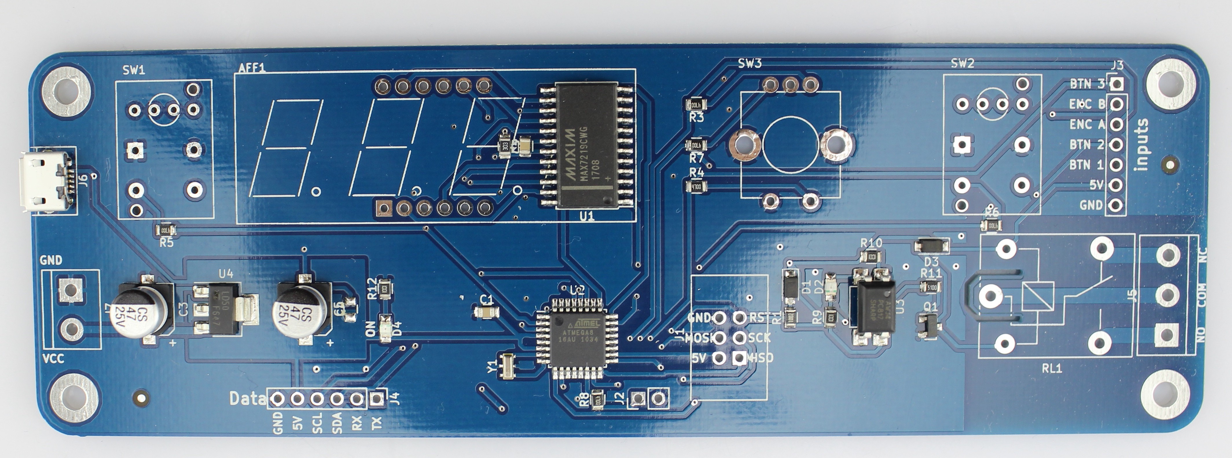
Here is the picture they sent me for review.![]()
-
Coding, coding, coding...
06/30/2017 at 20:09 • 0 commentsThe last days have been spent tunning Arduino code running on the timer.
A library to manage the MAX7219 seven-segments driver has been written, which can access all the chip settings, and three other libraries based on this one:
- One that won't be used, to drive a 8x8 led matrix, but that can be usefull for another project.
- One that effectively drives a seven segments display, with convenience functions like setting a digit, clearing it, setting and setting the digit's dot. I've also include a char set to display letters, that differs a bit from what I could find online, that is used by a setChar method that display a char, and a setText method that set several chars.
- And one that uses the previous, and offers convenience methods to directly set minutes and seconds.
Besides these libraries, the main code has been updated too. Until now the code was for using a shift register to drive the led display, it now uses the MAX7219 libraries mentionned above. I've also added some functions to naviguate trough a succinct menu. So the timer is now able to:
- Store a time in EEPROM, if it needs to be used in the future.
- Read a saved time from EEPROM
- Set and store the display luminosity
- Enable or disable the bell ringing at the end of an exposure.
So, I'm now waiting for the prototype boards to come home, before I can test the program in real condition! That will let some time to think about how using an accelarating feature on the rotary encoder, so that step value increments when turning more than a given time, to speed-up time tunning. And to think about the bell ringing, how long it should ring, if that long should be settable, and things like that...
All the sources for the main program and the libraries are on my github repository. Feel free to use them for whatever you want. The timer one can be usefull in a lot of programs, I whish I had write it a long time ago!
-
Prototypes ordered
06/15/2017 at 09:31 • 0 commentsThe first batch of prototypes has been ordered. Five boards with SMT soldered, plus one spare sithout components, that I will use/hack for programming. :)
And all the TH components has been order as well.It sould take about a month to have all those in my letter box, I can't wait for it! More to come...
![]()
Timer for UV printing bed.
This is a simple timer intended to control exposure of an UV printing bed used for photographic processes
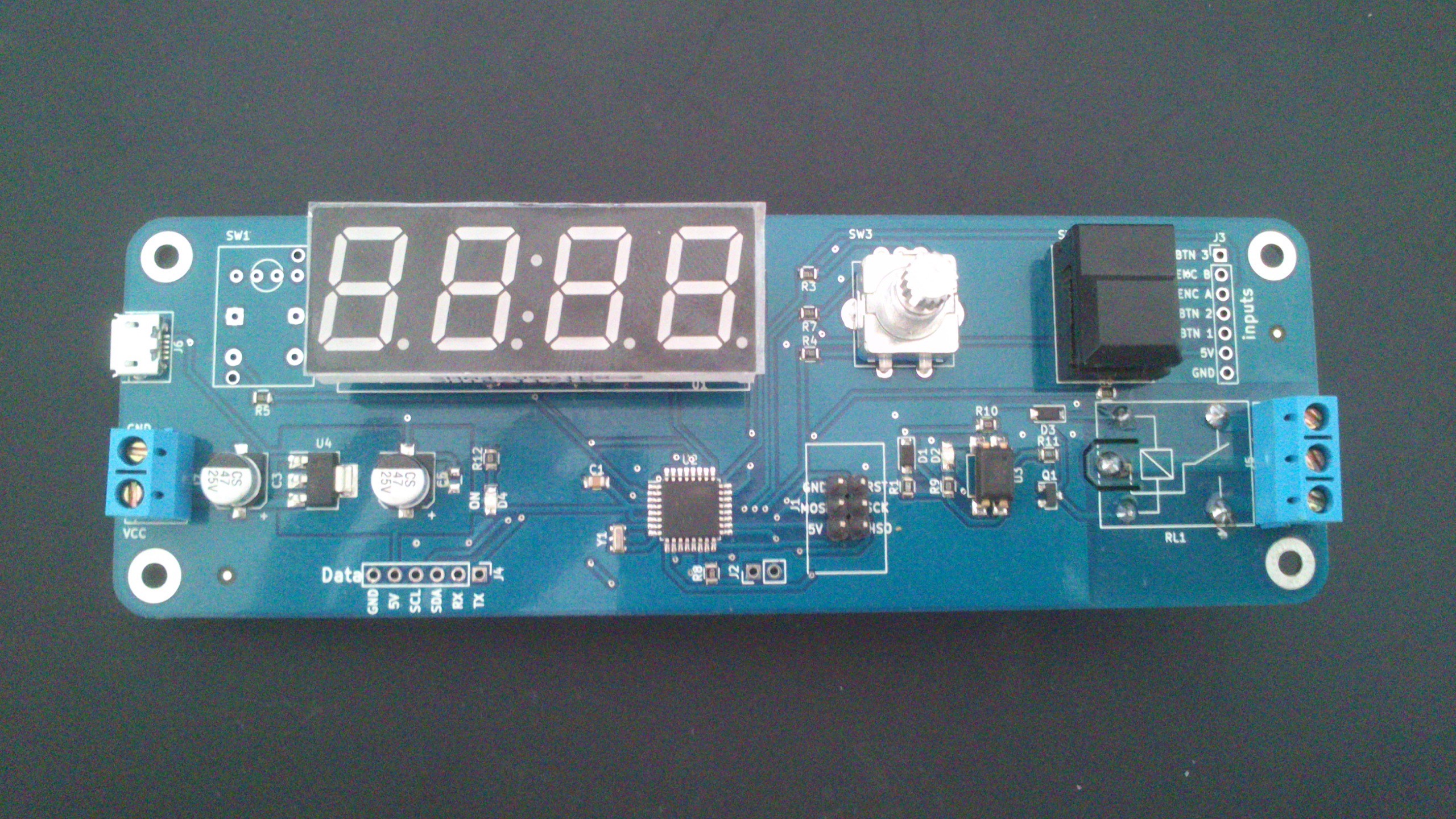 The finished timer. It just lacks the encoder button.
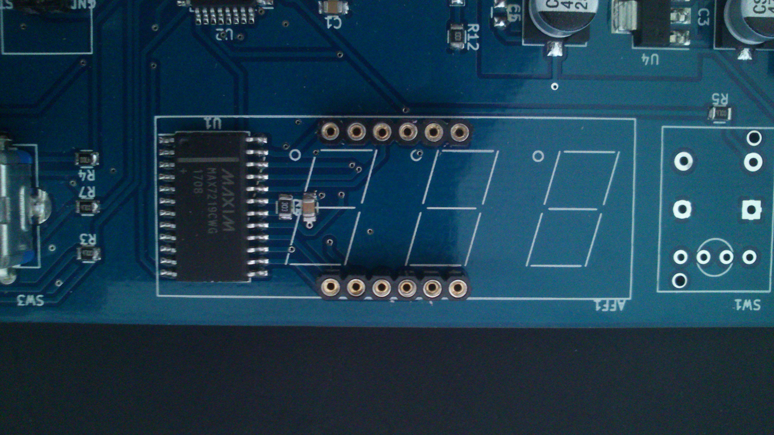 The C2 capacitor and the R2 resistor. Very close components, with the same index, I understand they swapped them. But i would have preferred they didn't! :)