 Mike Holden
-
1Parts List
I wanted a parts list with pictures, so it's here.
the 6 hull pieces, 3d printed. get the stl files 5 top pieces stl files inside 3d printed pieces (bulkhead, antenna shelf, autopilot shelf, battery mount) stl files ![]()
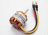
Motor. This one works well. D2830 1000kV with 3.17 (1/8”) shaft ebay 17.50 ![]()
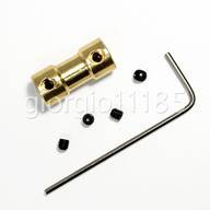
Prop shaft – motor coupler. 3.17mm to 3.17mm or whatever your parts are. ebay 6.50 ![]()
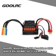
Speed Control. Waterproof, brushless ESC, 45A ebay 24.00 ![]()
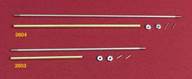
Prop shaft & tube 1/8 shaft. I ended up using K&S tubing for the tube because the dumas one was too short. dumas 2604 9.00 ![]()
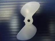
Propeller 1/8 inch shaft, 1.75 inch diameter. dumas 3003 1.40 ![]()
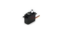
Standard servo for steering. I had a JR DS811 handy but they are out of production. Horizon hobby 10.00 ![]()
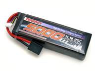
5000 mAh 3 cell lipo battery (11.1V) Tenergy or similar 50.00 ![]()
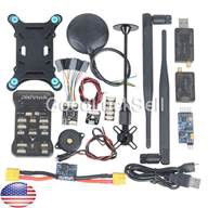
Pixhawk PX4 autopilot set. You need: • Pixhawk • Power module • Gps/compass • 915 MHz modems Other stuff is optional. ebay (shop around, there are many suppliers) 180.00 ![]()
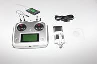
Radio Transmitter and receiver. Many options but I like my Flysky fs-i6s with fs-IA10B receiver, with tablet holder. 80.00 -
2Print the pieces for the hull.
I used PLA for the first hull, it's plenty strong but I worry when I have to leave it in my car on a hot day.
https://www.thingiverse.com/thing:3491904
I will try ABS or PETG for the next boat. If you try this please let me know how it works.
Files are in a link off to the left on the main project page.
- There are 6 hull pieces (one was uploaded twice to try to fix manifold issues). I used 10% infill, do your best with the settings to make the layers stick together very well and be water-tight. The pieces should not need supports if you print them nose-up.
- There are 5 Hatch pieces. I printed these upside-down. You need support for the overhangs if you do this.
- There are several interior pieces too:
- a battery holder (in 2 pieces to print flat easier)
- a motor mount bulkhead
- shelves to hold the pixhawk and antennas.
- There is also the rudder to print, and the rudder arm (print the arm in abs if possible, my PLA version cracked but held up okay after I epoxied it together again, but the ABS version is looking good). The rudder shaft is brass rod, and a short 4-40 screw and nut are needed to finish the rudder arm.
-
3Glue the hull together.
Glue the hull together. I used 5 minute epoxy. Tape it together as you go. You can stand the stern piece on the transom and glue them in a stack, or you can glue them with the hull upside-down on a flat surface (the hatch lip is a planar surface). Make sure the boat is straight!
![]()
Glue the hatch together too on a flat surface.
Put the hatch seal on and hatch latches. I've used hooks on the hull and rubber-bands for hatch hold-down but maybe you can come up with a better arrangement?
Before installing any hardware, put the hatch on the hull, seal the prop/rudder holes with tape or hot glue, and dunk the boat underwater. Fix any leaks now! I had to put a coat of epoxy on the hull to keep water from seeping through the 3-D printed layers, it was slightly porous
If you mount your antennas like I did, print and glue the antenna covers on the hatch. Otherwise, glue a scrap of plastic over the holes to keep the water out.
-
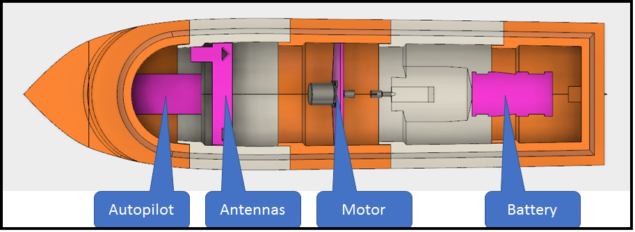
4Install the inside pieces
Install the inside pieces with 5 minute epoxy.
![]()
-
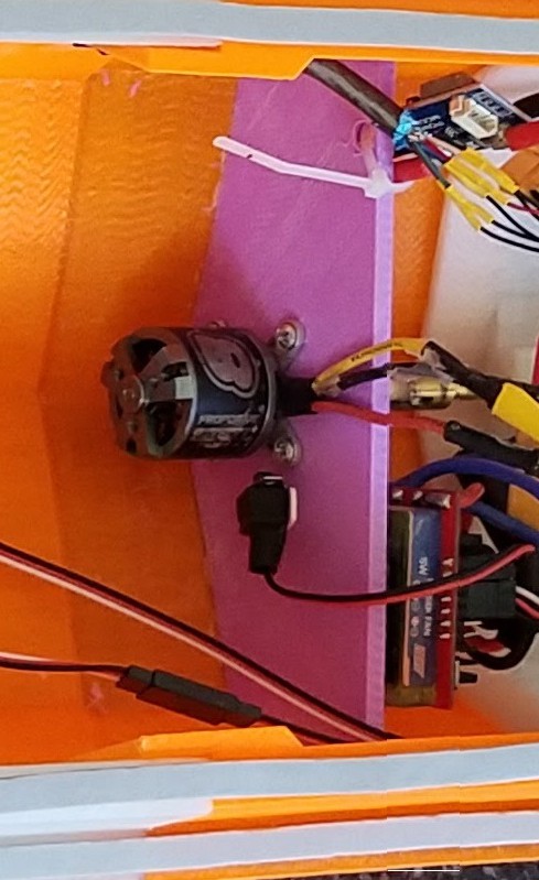
5Install the motor, shaft and prop.
Install the motor, shaft and prop. My original motor mounted on the forward side of the bulkhead, but I later replaced it with one that mounts on the aft side. I've included pictures of both. Mounting it on the forward side I used a "dog bone" connector (from dumas) which allows for some misalignment, but also would pull apart when reversing. The updated motor is mounted with a solid connector and seems to work great.
![Motor mounted in front of bulkhead.]()
Use loctite or your prop will come loose in the middle of the ocean!
The stuffing tube is a brass tube that the propeller shaft goes through. The dumas tube was a bit short so I used a brass tube from the K&S stand at the hardware store. Carefully epoxy the tube in place. Make sure it is aligned with the motor! Make sure no glue gets inside!
I attached the shaft to the motor while the glue set to keep it aligned.
In the picture below you can see I plugged the tube with tape (thin packing tape so it fits through the hole). Next time I think I would tape the prop shaft in the tube so the tape could stay on while you align the motor.
-
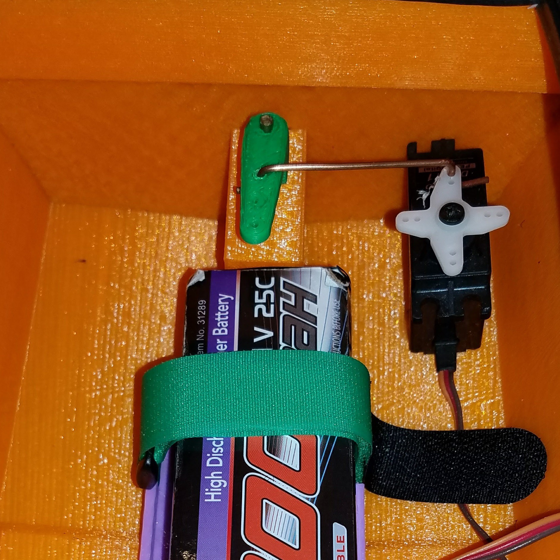
6Install the rudder, rudder servo and linkage.
Install the rudder, rudder servo and linkage. I just glued the servo in. The linkage is from a scrap of copper household wire-- put it in then mount the rudder arm last. The rudder shaft is glued into the rudder. There is a rudder tube glued into the hull similar to the prop shaft installation. A nut fits into the rudder arm and a screw pinches the rudder shaft to hold it together.
![]()
-
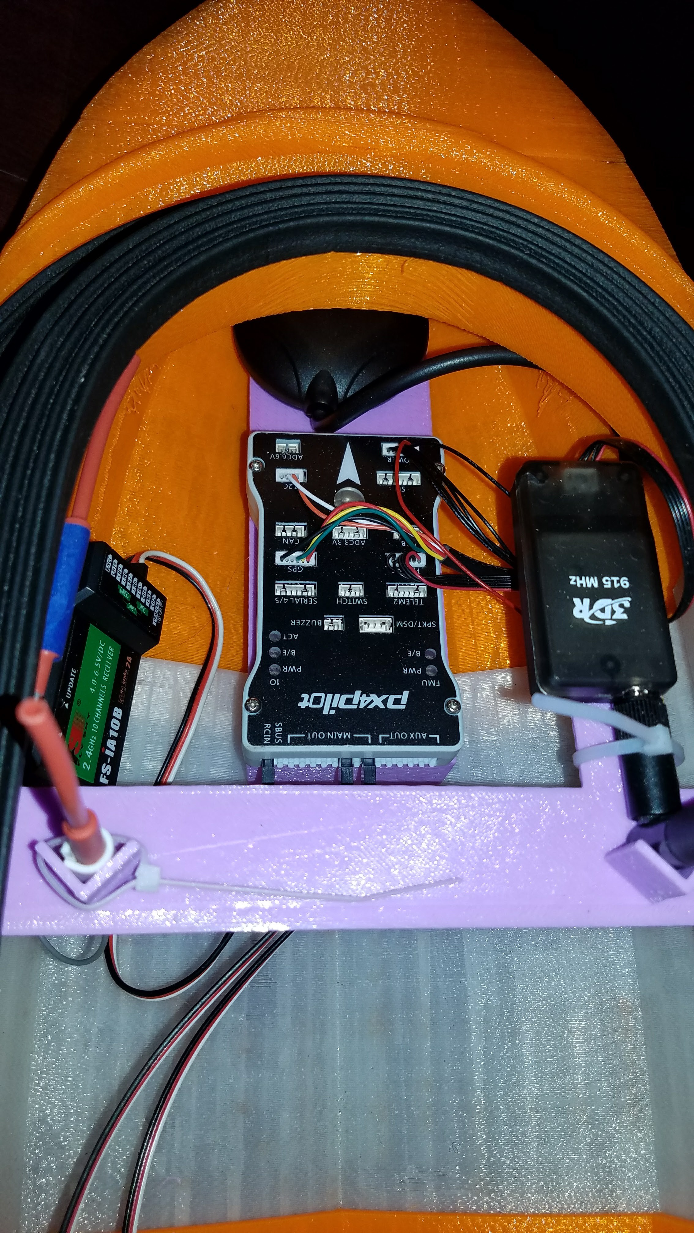
7Mount the electronics.
Mount the electronics. I used double-stick foam tape, velcro, and zip ties for this. Make sure the GPS/Compass is mounted securely and oriented properly, if it comes loose your boat will try to steer to compensate and bad things will happen. The pixhawk also must be firmly mounted.
![]()
-
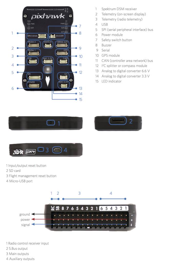
8Connect all the wires.
Connect all the wires. I had to extend the power connector cable (from power module to pixhawk) so it would reach. Use the guide shown here. I skipped the button and buzzer on my boat but can't say that's the best option.
![]()
-
9Bench testing
Bench testing, APM calibration, APM configuration.
Follow the guide at ardupilot.org
-
10Measurement Payload
Add instrumentation system.
More details soon!
n3m0 the autonomous boat
A 3-D printed boat that uses an APM autopilot for autonomous operations. Designed for citizen scientists to make oceanographic measurements.

Discussions
Become a Hackaday.io Member
Create an account to leave a comment. Already have an account? Log In.